9.14 Pocketing
Micky R. Jennings

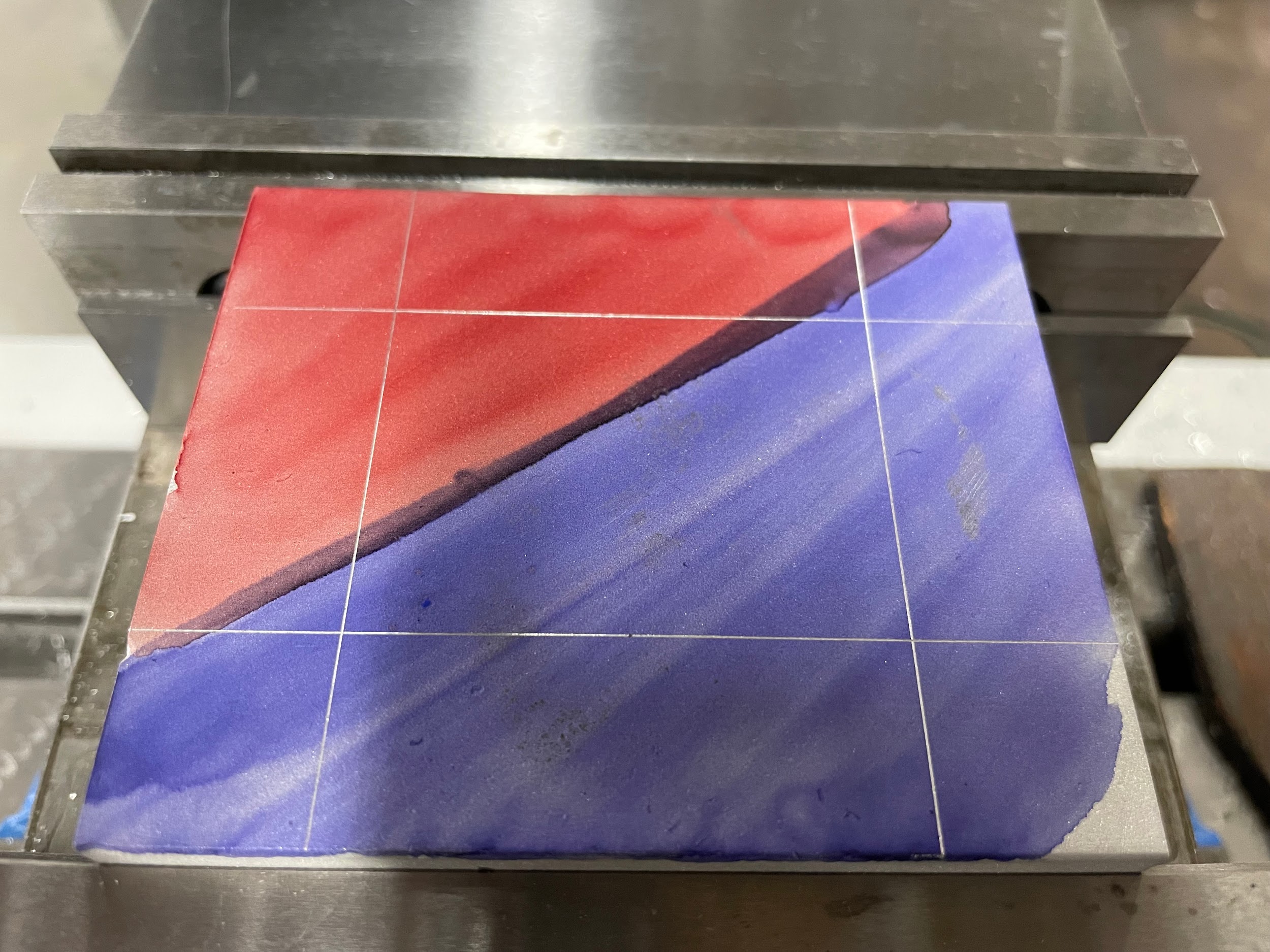
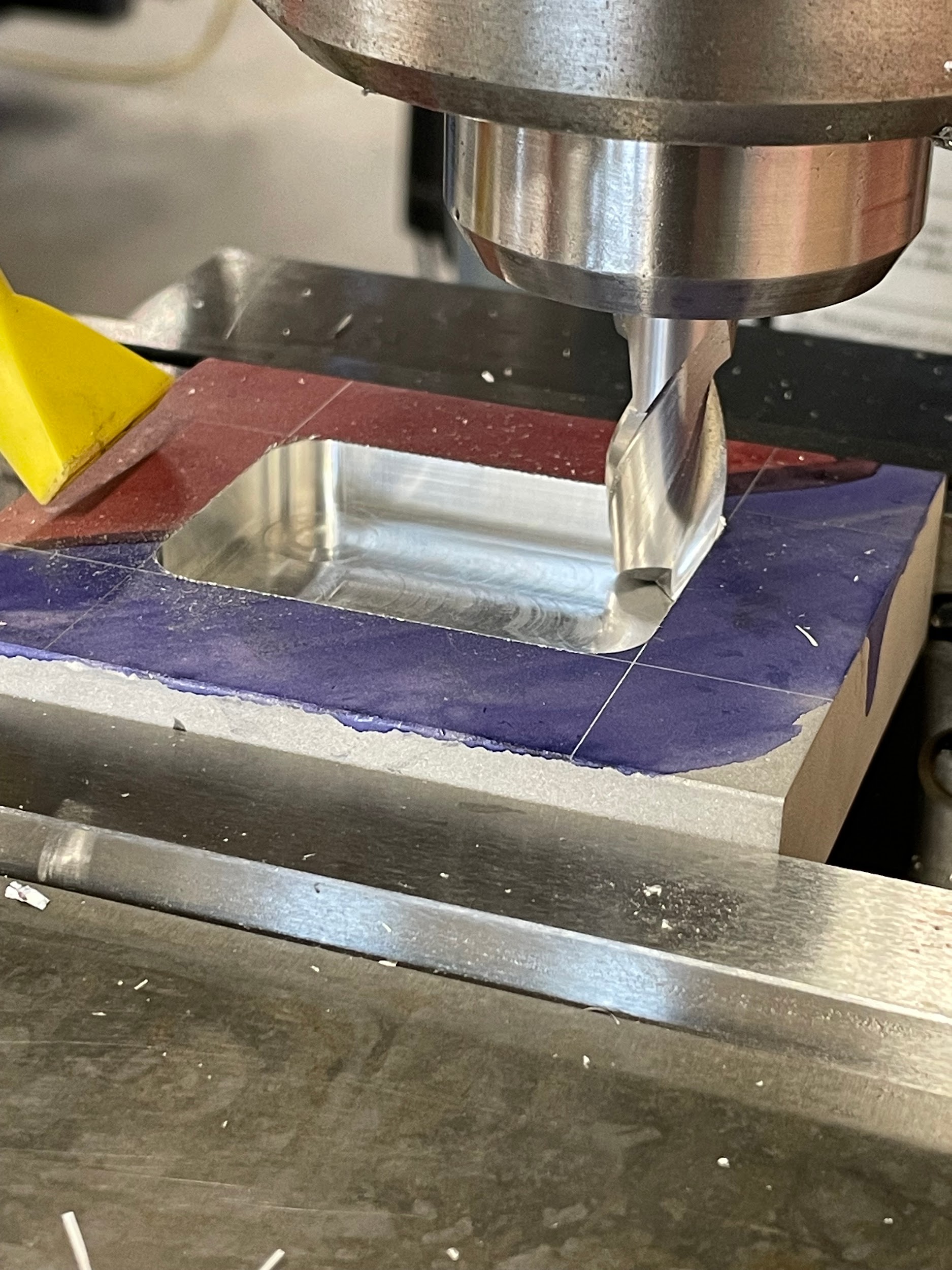
Figure 9.180. An end mill rests inside a finished pocket on a manual milling machine. / Image Credit: Micky R. Jennings, courtesy of Wenatchee Valley College, CC BY 4.0
Pocketing is the process of creating a recessed cut inside of the outer contour of a part. A simple pocket is generally round or rectangular shaped and at a singular depth. However, pockets can be any shape the designer desires and can contain multiple steps and depths.
Step by step process for pocketing:
- Apply layout dye to the area that will receive a pocket.
- Layout the pocket’s boundary.
- A hole may be drilled of similar size to the endmill required to mill out the pocket, generally the same size as the internal radii. Drill the hole to about 1/64″ from finished pocket depth.
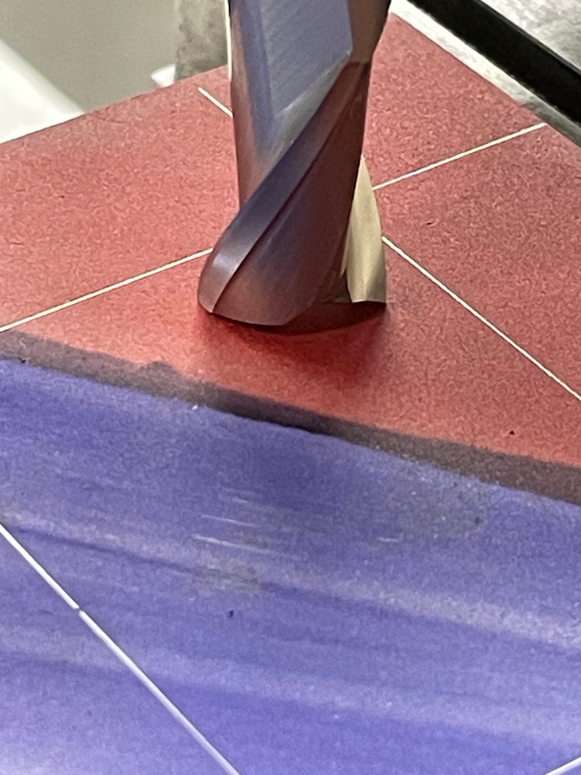
- Load an end mill into the milling machine equal to the interior radii of the pocket’s corners.
- Calculate the spindle speed of the endmill chosen.
- Turn on the spindle.
- Engage the end mill into the workpiece to depth.
-
- Use a previously drilled hole.
-
-
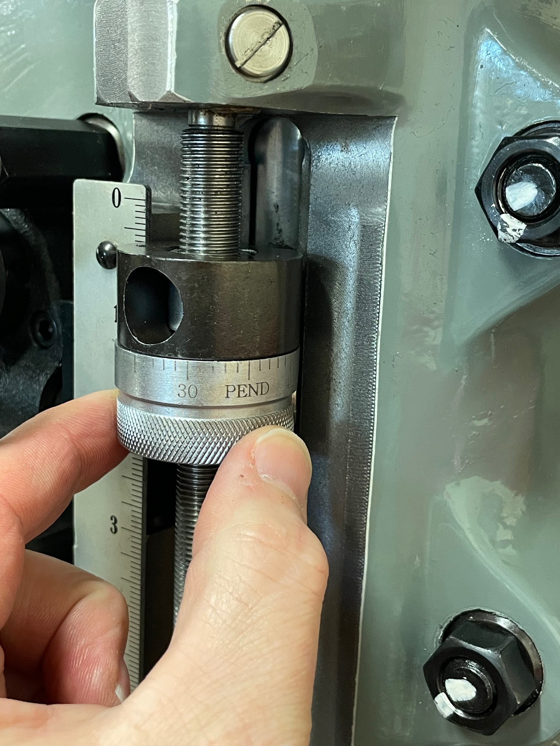
- Lock the quill
- Touch the tool off the top of the work with the knee.
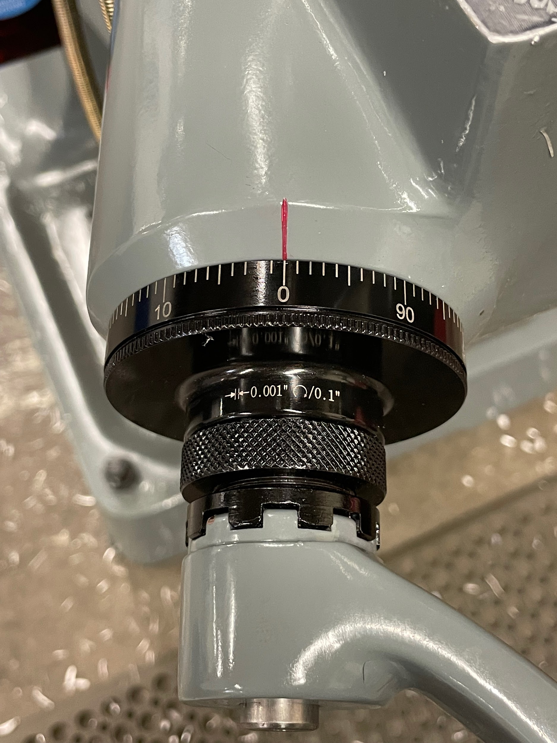
- Zero knee collar.
- Raise the knee inside the drilled hole.
-
-
- Use the endmill to plunge to depth.
-
-
- Toughing off the top of the work with the quill.
- Set the quill stop.
- Zero knee collar.
- Raising the knee to set the depth.
- Gently plunge the endmill to depth using the quill, breaking chips when needed.
- Lock the quill at final depth.
-
-
- Ramp into the work with an endmill.
-
-
- Lock the quill
- Touch the tool off the top of the work with the knee.
- Zero knee collar.
- Gradually move the knee and table/saddle handwheel simultaneously to create a shallow ramp.
- Continue back and forth until the desired depth is reached.
-
- Apply some initial cutting oil and continue throughout the cutting process.
- Rough the material from the inside of the pocket visually, leaving 1/32″ of an inch on the walls and 1/64″ on the floor for a finishing operation. An air blast can aid in chip removal and help prevent re-cutting chips and damaging the tool.
- Load a finishing end mill if needed, touch off the top of the work, and bring the tool to the full depth inside the pocket.
- Finish the bottom of the pocket.
- Gently make skim cuts along all four sides, recording the handwheel positions on each side.
- Measure the part and calculate the material remaining on the four surfaces.
- Calculate the positions of the tool to remove the rest of the material, minus .010″ for a final finish.
- Conventional mill to the calculated positions.
- Measure the part and calculate the material remaining on the four surfaces.
- Calculate the positions of the tool to remove the rest of the material, making a final finish pass.
- Climb mill to the calculated positions.
- Measure the finished pocket size.
Step 2: Layout the pocket’s boundary.
Step 7-b-i: Toughing off the top of the work with the quill.
Step 7-b-ii: Set the quill stop.
Step 7-b-iii: Zero knee collar.
Step 7-b-v: Gently plunge the endmill to depth using the quill, breaking chips when needed.

Step 7-c-ii: Touch the tool off the top of the work with the knee.

Step 7-c-iv-v: Gradually move the knee and table/saddle handwheel simultaneously to create a shallow ramp. Continue back and forth until the desired depth is reached.

“Step 9: Rough the material from the inside of the pocket visually, leaving 1/32″ of an inch on the walls and 1/64″ on the floor for a finishing operation. An air blast can aid in chip removal and help prevent re-cutting chips and damaging the tool.”

Step 13: Measure the part and calculate the material remaining on the four surfaces.
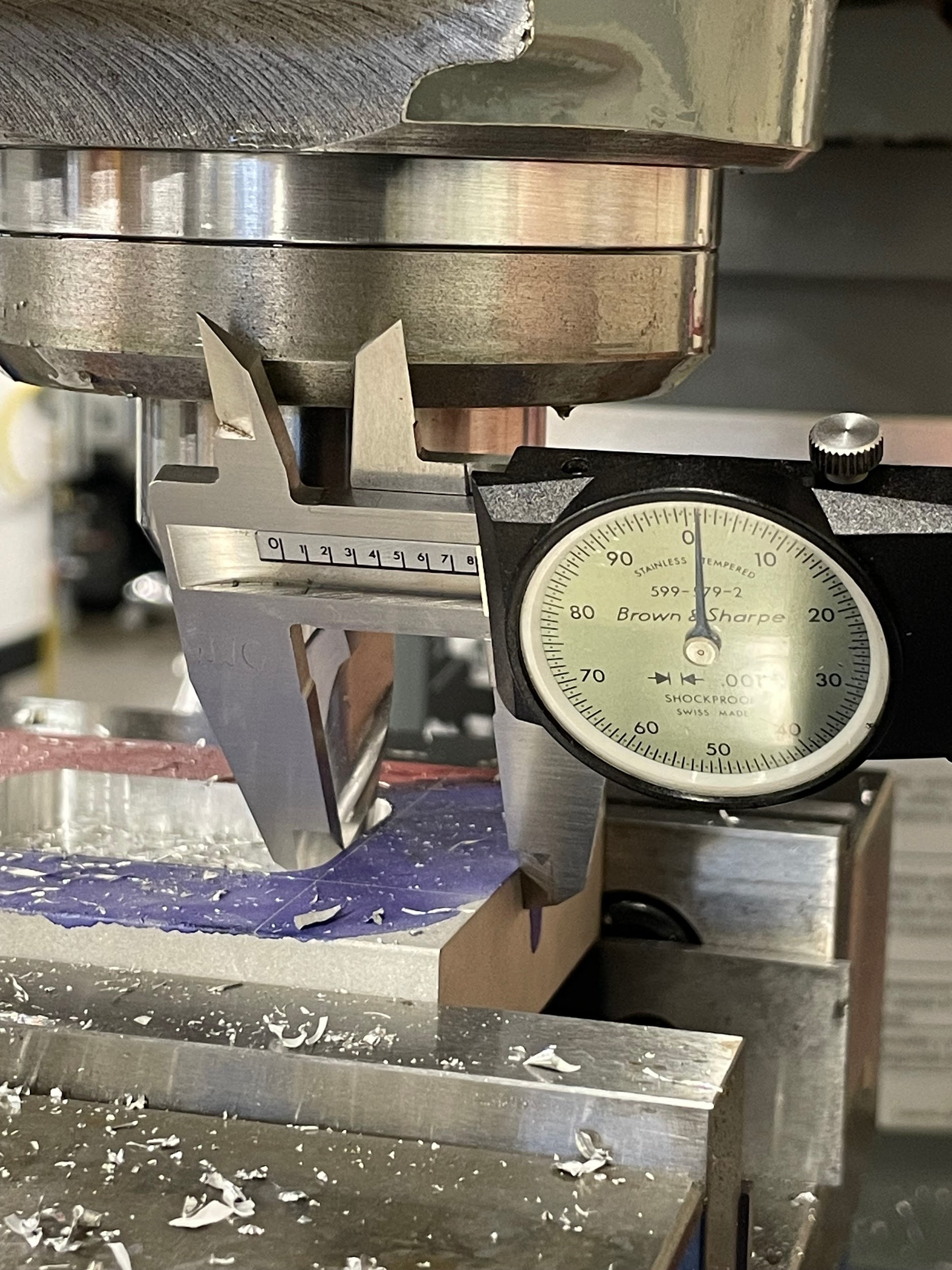
Step 13: Measure the part and calculate the material remaining on the four surfaces.
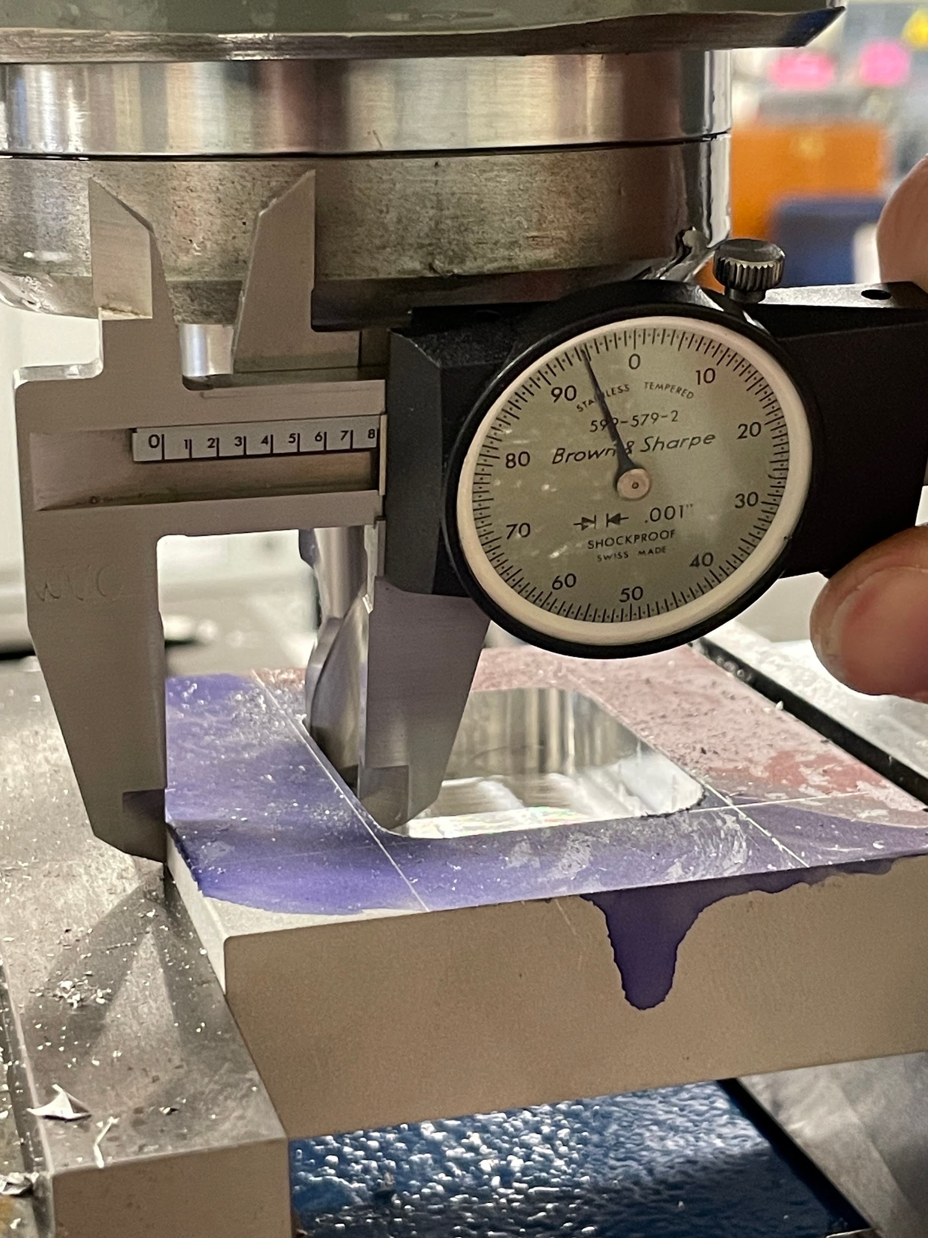
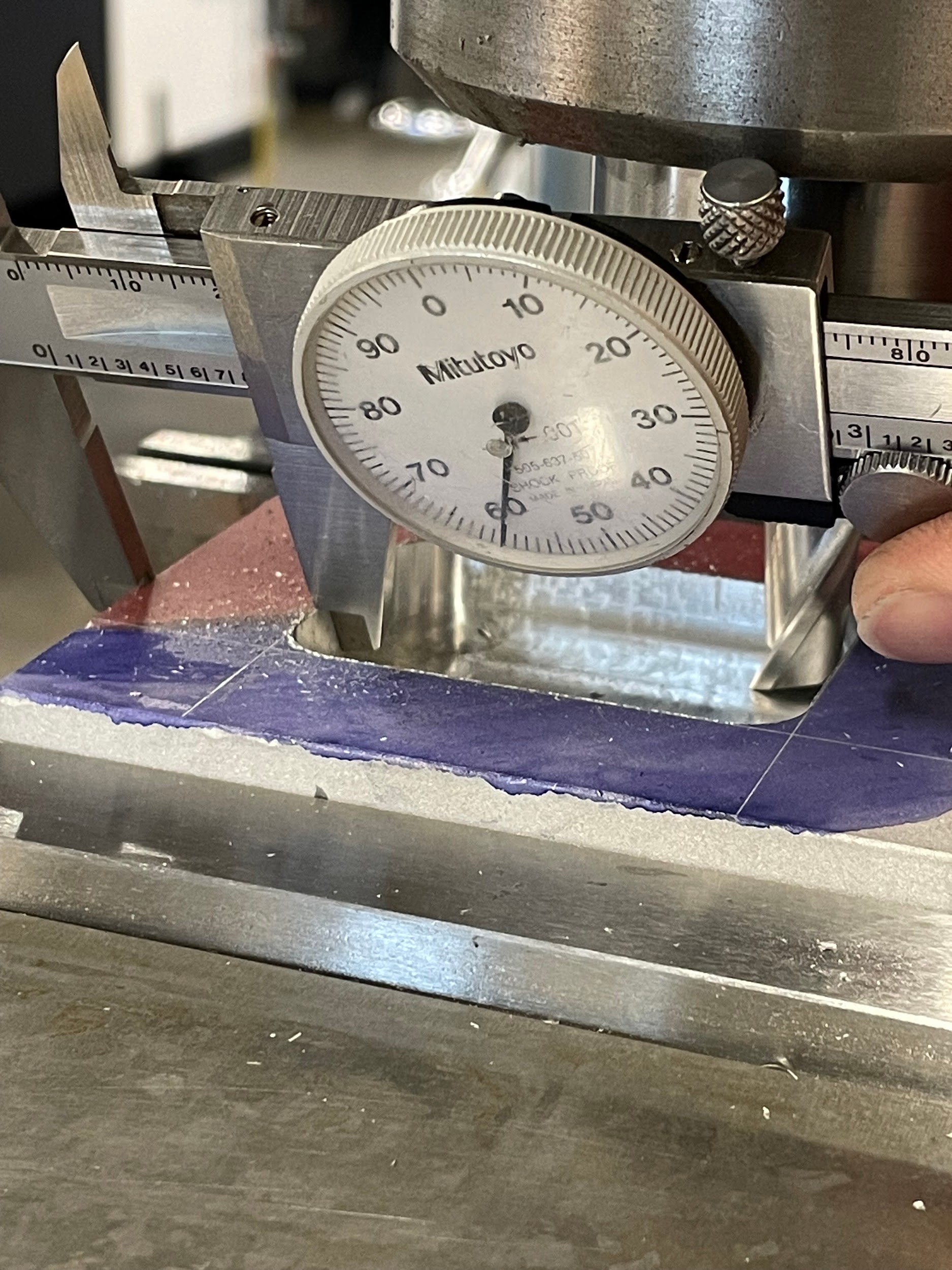
Step 16: Measure the part and calculate the material remaining on the four surfaces.
Step 18: Climb mill to the calculated positions.

Step 18: Climb mill to the calculated positions.
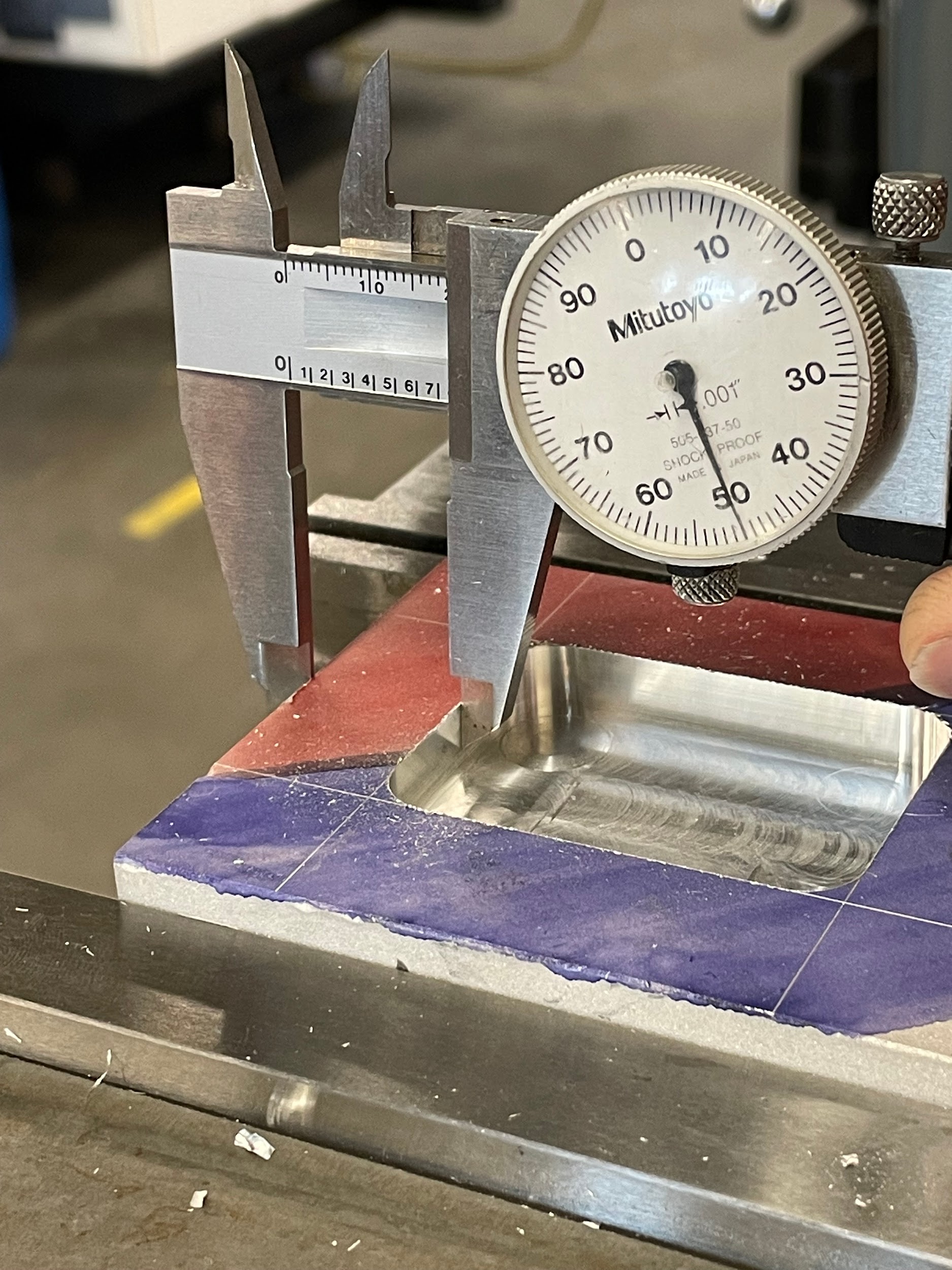
Step 19: Measure the finished pocket size.
Attributions
- Figure 9.180: Finished pocket by Micky R. Jennings, courtesy of Wenatchee Valley College, for WA Open ProfTech, © SBCTC, CC BY 4.0
- Figure 9.181: Pocket layout lines by Micky R. Jennings, courtesy of Wenatchee Valley College, for WA Open ProfTech, © SBCTC, CC BY 4.0
- Figure 9.182: Touch off endmill by Micky R. Jennings, courtesy of Wenatchee Valley College, for WA Open ProfTech, © SBCTC, CC BY 4.0
- Figure 9.183: Set quill stop by Micky R. Jennings, courtesy of Wenatchee Valley College, for WA Open ProfTech, © SBCTC, CC BY 4.0
- Figure 9.184: Zeroing the knee by Micky R. Jennings, courtesy of Wenatchee Valley College, for WA Open ProfTech, © SBCTC, CC BY 4.0
- Video 9.52: Micky R. Jennings, courtesy of Wenatchee Valley College, for WA Open ProfTech, © SBCTC, CC BY 4.0
- Video 9.53: Micky R. Jennings, courtesy of Wenatchee Valley College, for WA Open ProfTech, © SBCTC, CC BY 4.0
- Video 9.54: Micky R. Jennings, courtesy of Wenatchee Valley College, for WA Open ProfTech, © SBCTC, CC BY 4.0
- Video 9.55: Micky R. Jennings, courtesy of Wenatchee Valley College, for WA Open ProfTech, © SBCTC, CC BY 4.0
- Figure 9.185: Measuring the right side of the pocket by Micky R. Jennings, courtesy of Wenatchee Valley College, for WA Open ProfTech, © SBCTC, CC BY 4.0
- Figure 9.186: Measuring the front of the pocket by Micky R. Jennings, courtesy of Wenatchee Valley College, for WA Open ProfTech, © SBCTC, CC BY 4.0
- Figure 9.187: Measuring the left side of the pocket by Micky R. Jennings, courtesy of Wenatchee Valley College, for WA Open ProfTech, © SBCTC, CC BY 4.0
- Video 9.56: Micky R. Jennings, courtesy of Wenatchee Valley College, for WA Open ProfTech, © SBCTC, CC BY 4.0
- Figure 9.188: Finished pocket by Micky R. Jennings, courtesy of Wenatchee Valley College, for WA Open ProfTech, © SBCTC, CC BY 4.0
- Figure 9.189: Measuring the finished pocket by Micky R. Jennings, courtesy of Wenatchee Valley College, for WA Open ProfTech, © SBCTC, CC BY 4.0
The process of using an end mill to cut recessed features on the face of a workpiece.
