9.15 Angle Milling
Micky R. Jennings
Angle milling is the process of creating an angled cut on a workpiece. This can be done in multiple different ways on a manual milling machine.
Holding the part in a vise at an angle is a good option for angle milling. This option is the quickest and can often be accomplished by using angle blocks. For added precision, dialing in the parts using trigonometry and a drop indicator is a popular method.
Smaller angular cuts, like chamfers, often utilize form cutters ground to the precise angle needed. For 45-degree angles that don’t need to be extremely accurate, the angled edges of a face mill work well.
Some angel milling methods are best for a larger work volume and are inefficient for smaller jobs. For instance, the machinist can adjust the milling head at one or more of the joints that attach the head to the ram to create angle cuts. This is a good option if there are many parts to be machined; however, if there are just a few parts, altering the milling head can be unnecessarily cumbersome.
Similarly, custom fixtures are a great option if high volumes of parts are to be cut at angles. A fixture can hold the part at a specific angle and allow for the angle to be milled on the part. This isn’t the best option for just a couple parts because a fixture will take extra time to design and machine.
Step by step process for milling an angle using angle blocks:
- Select an angle block that corresponds to the angled feature of the part.
- Load the part, along with the angle block, in the vise on parallels.
- Load an end mill or face mill into the milling machine. Generally, a tool that will accomplish the cut in one pass is best.
- Calculate the spindle speed and feed rate for the tool selected.
- Turn on the spindle and adjust the speed.
- Lock the quill.
- Gently touch the tool off to the prominent corner by raising the knee.
- Zero the knee.
- Calculate the amount to be removed from the part using right angle trigonometry.
- Remove the necessary material over multiple passes using face milling cuts.
- Turn off the spindle.
- Lower the knee.
- Clean and inspect the feature.
Step 1: Select an angle block that corresponds to the angled feature of the part.
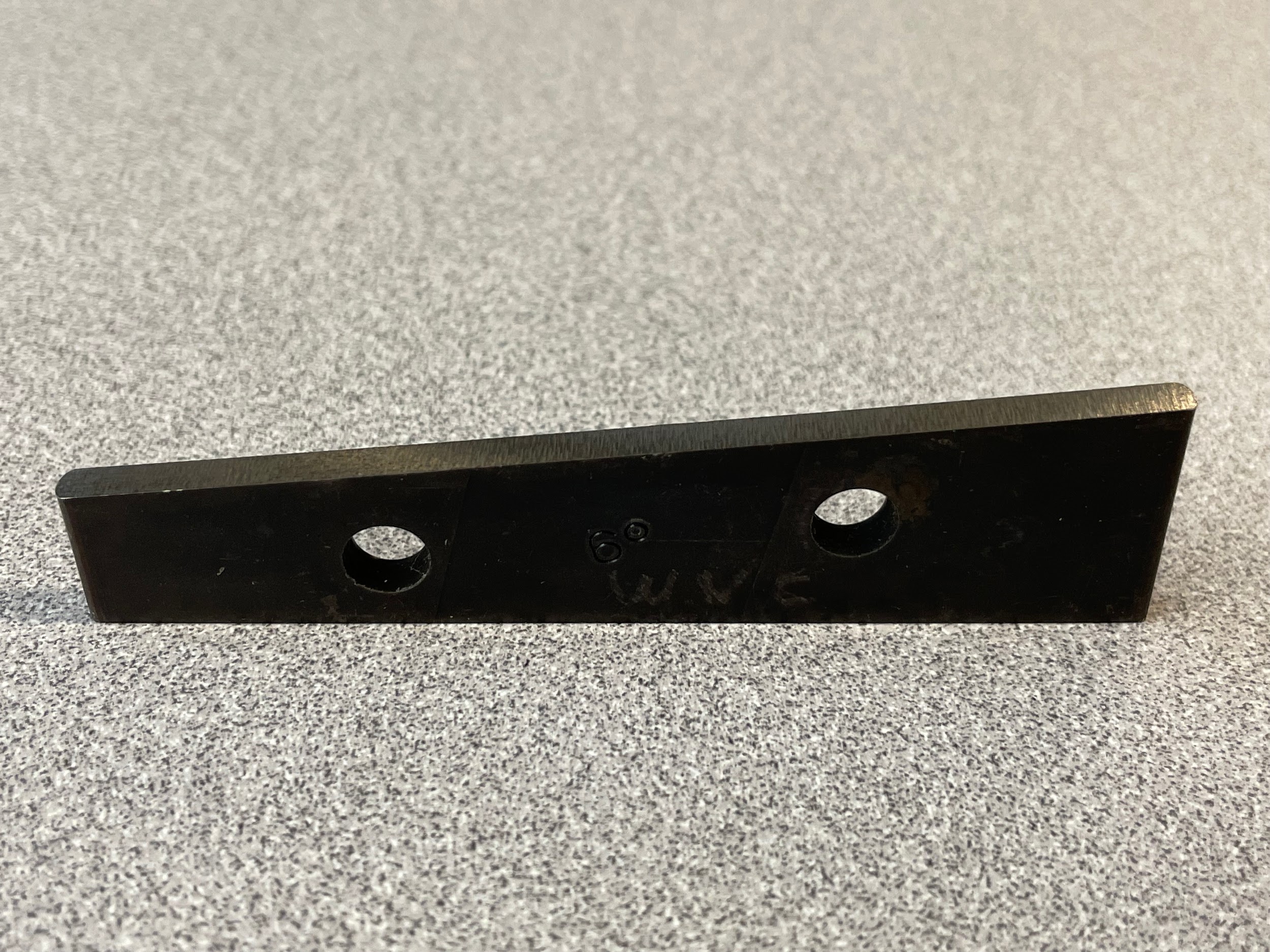 Figure 9.191. A precision 6 degree angle block stands upright on a table. The block is ⅛” thick. / Image Credit: Micky R. Jennings, courtesy of Wenatchee Valley College, CC BY 4.0
Step 2: Load the part, along with the angle block, in the vise on parallels.
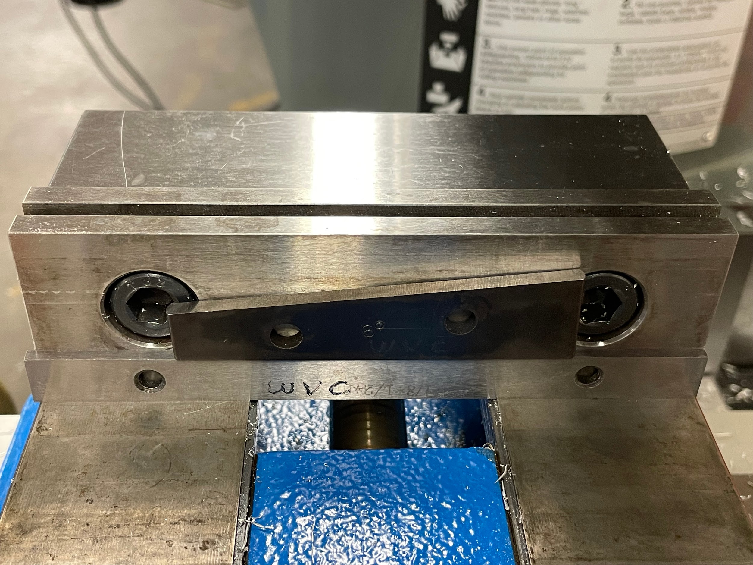
Step 2: Load the part, along with the angle block, in the vise on parallels.

Step by step process for milling an angle by dialing in the part at an angel in the vise:
- Load the part in the vise, one end on parallels, handled at the approximate angle of the required cut.
- Lightly tighten the vise.
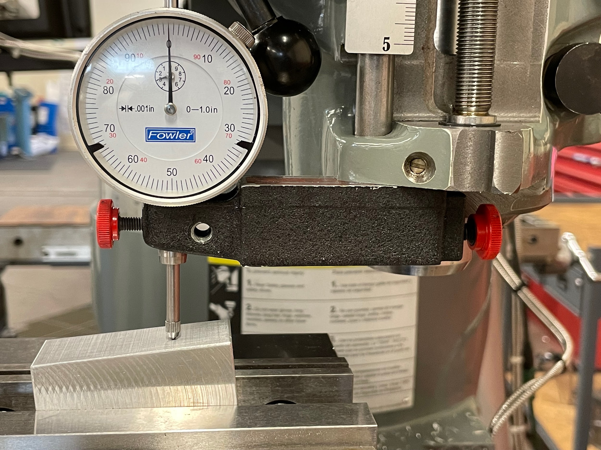
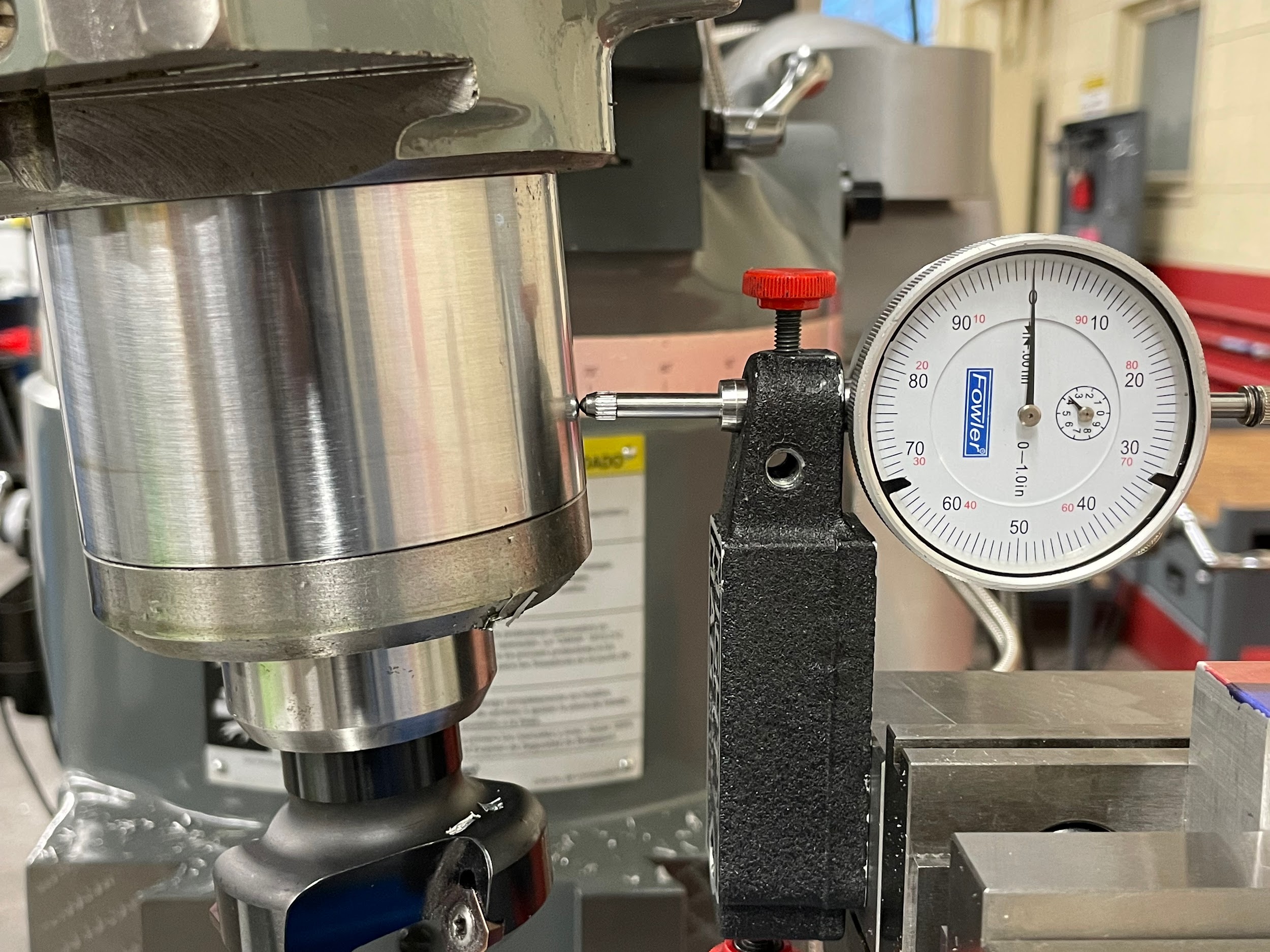
- Attach a drop indicator to the head so that the indicator shaft is vertical.
- Calculate the amount of the vertical leg of the triangle associated with the angular cut. In the example shown, a 6-degree angle is to be cut. The operator can use whatever horizontal distance they like, but one that is an even number and easy to calculate is best. In this example, 1.000″ is used. The surface of the part makes up the hypotenuse, the operator moving the table makes one leg of the triangle, and the drop of the indicator makes the other leg. Knowing that the angle and one leg are given, and the other leg is in question, the tangent formula will be used. The calculation looks like this:
Tan angl = opp/adj
Tan 6° = Z/1.000″
Tan 6° × 1.000″ = Z/1.000″ × 1.000″
Tan 6° × 1.000″ = Z
.105″ = Z
- Raise the knee so the indicator is depressed by at least .100 more than the amount of the calculated drop.
- Remove any backlash in the table movement and zero the graduated collar.
- Zero the indicator.
- Move the table by exactly 1.000.
- Read the drop in the indicator. If the drop isn’t accurate to the calculated leg, gently adjust the part and remeasure until the drop is within tolerance.
- Load an end mill or face mill into the milling machine. Generally, a tool that will accomplish the cut in one pass is best.
- Calculate the spindle speed and feed rate for the tool selected.
- Turn on the spindle and adjust the speed.
- Lock the quill.
- Gently touch the tool off to the prominent corner by raising the knee.
- Zero the knee.
- Calculate the amount to be removed from the part using right angle trigonometry.
- Remove the necessary material over multiple passes using face milling cuts.
- Turn off the spindle.
- Lower the knee.
- Clean and inspect the feature.
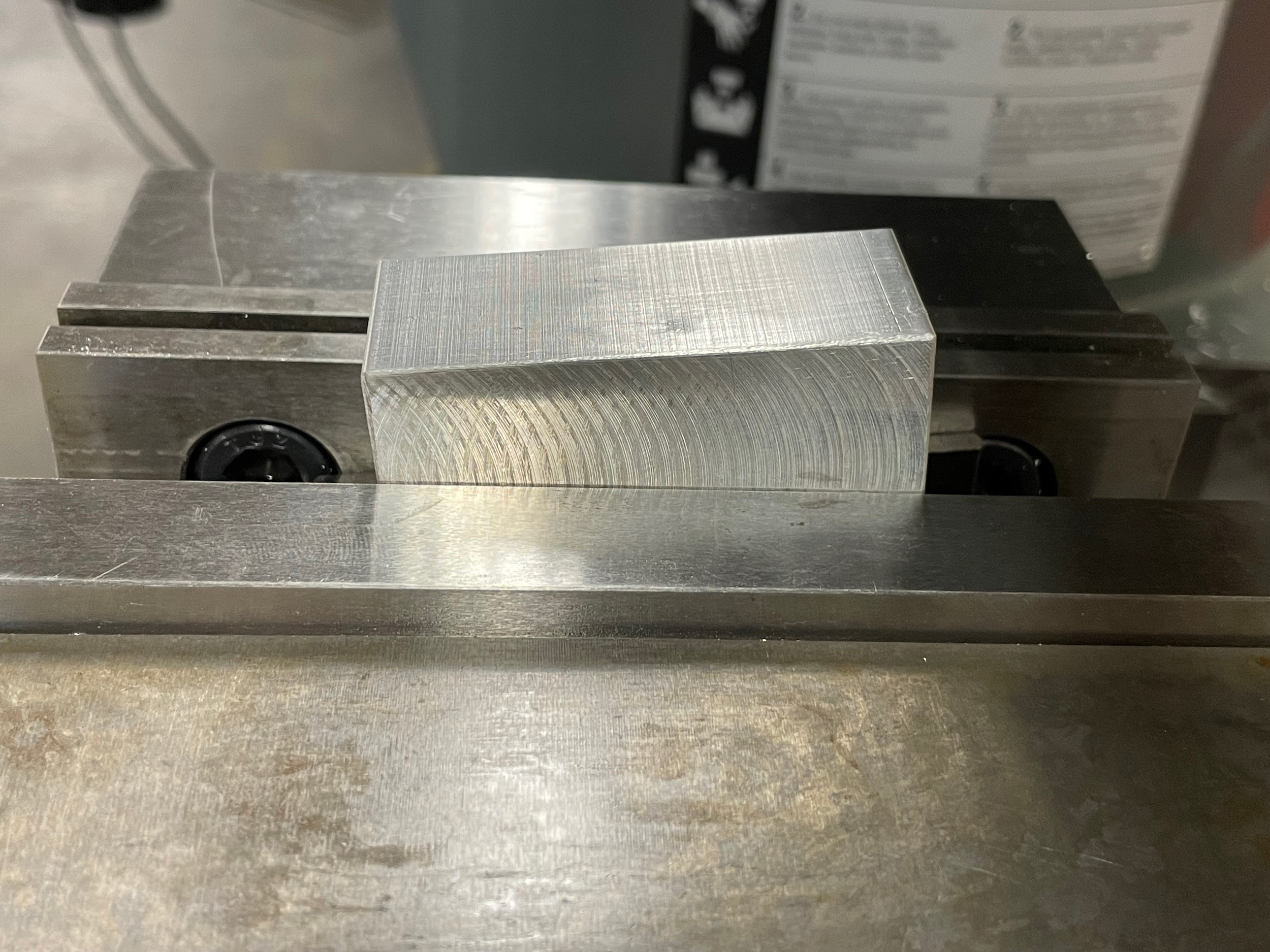
Step 1: Load the part in the vise, one end on parallels, handled at the approximate angle of the required cut.
Step 3: Attach a drop indicator to the head so that the indicator shaft is vertical.
Step 7: Zero the indicator.
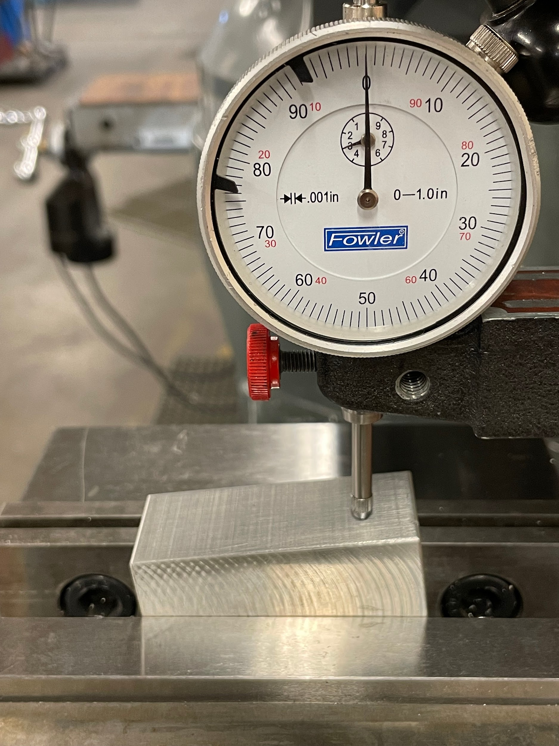
“Step 9: Read the drop in the indicator. If the drop isn’t accurate to the calculated leg, gently adjust the part and remeasure until the drop is within tolerance.”

Step 9: Read the drop in the indicator. If the drop isn’t accurate to the calculated leg, gently adjust the part and remeasure until the drop is within tolerance.

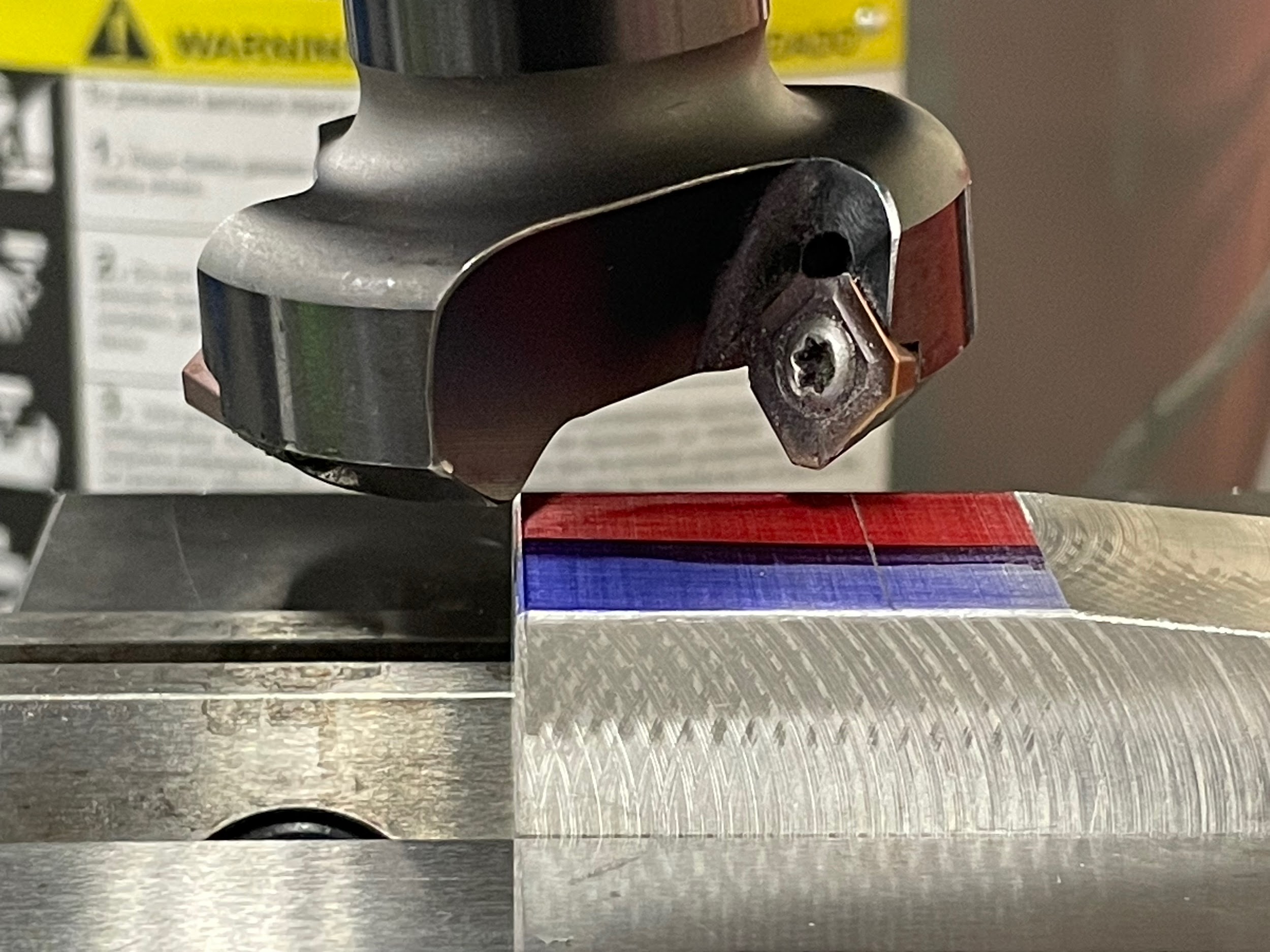
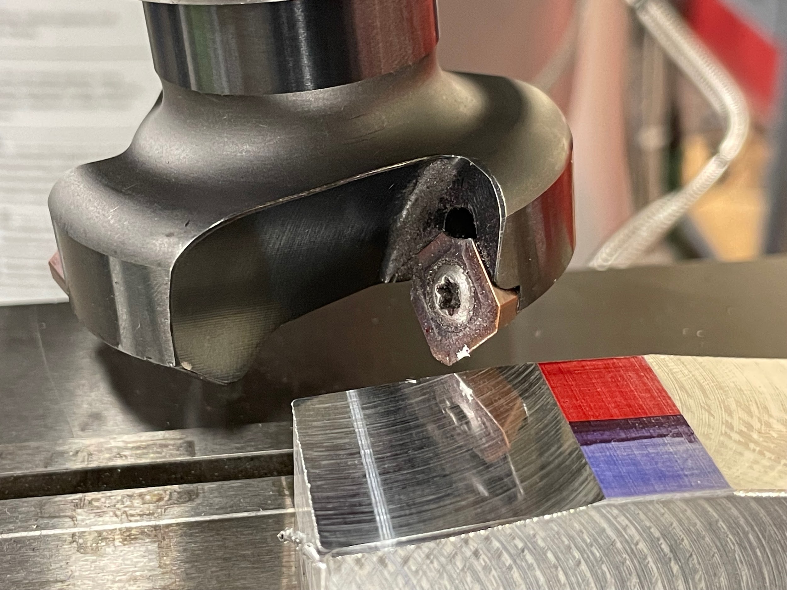
Step 14: Gently touch the tool off to the prominent corner by raising the knee.
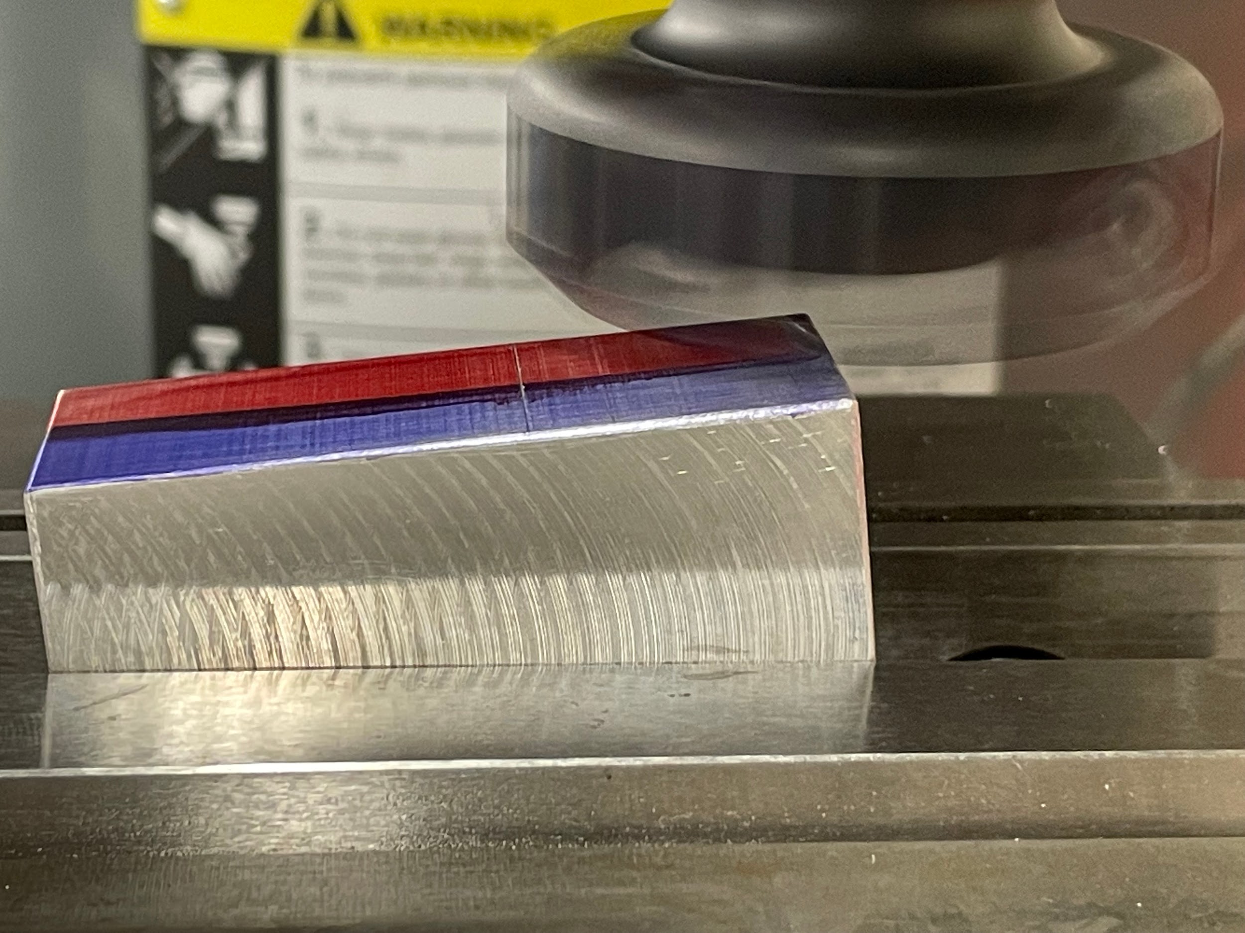
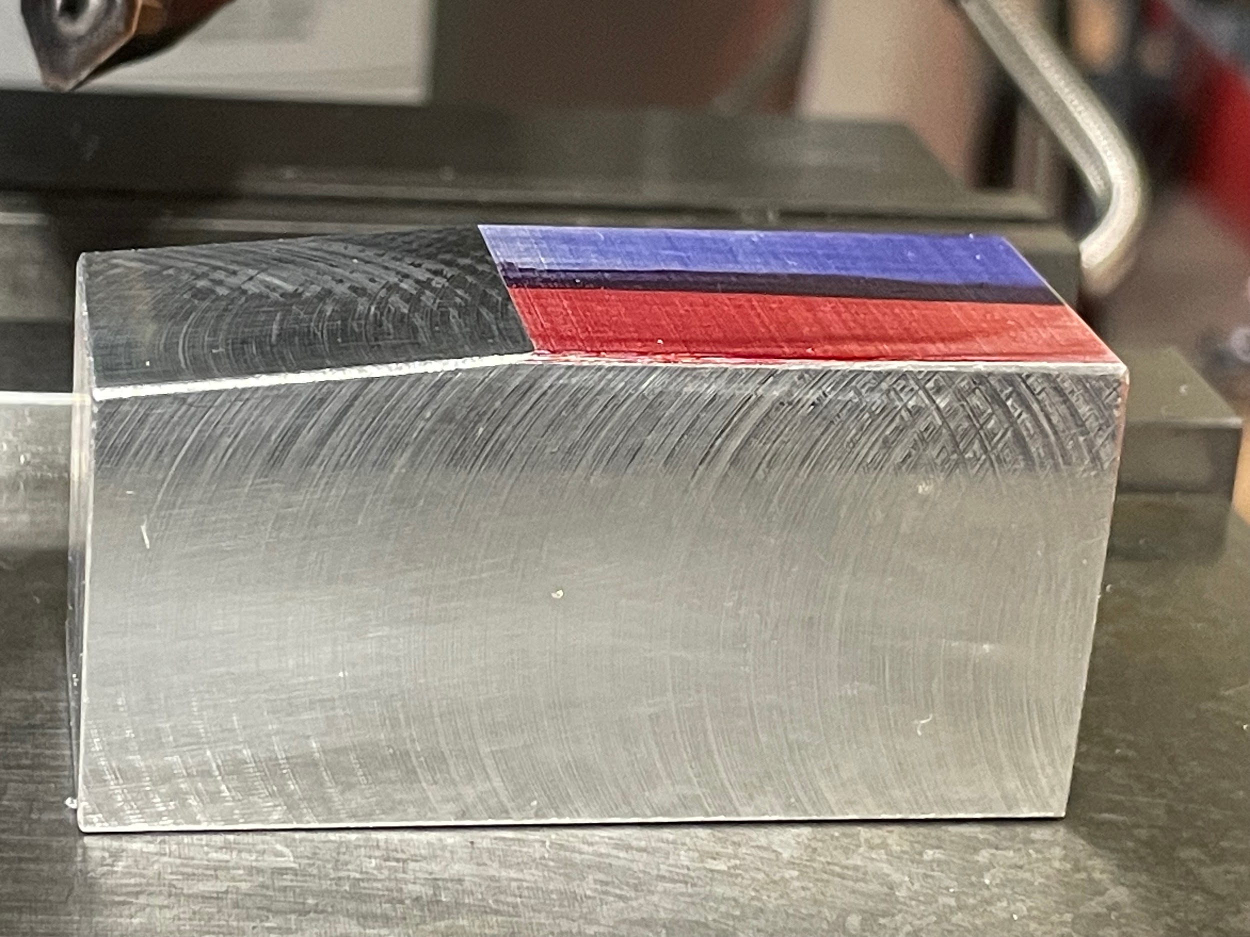
Step 17: Remove the necessary material over multiple passes using face milling cuts.

Step 17: Remove the necessary material over multiple passes using face milling cuts.

Step by step process for milling angles by tilting the milling head:
- Load the part flat in the vise on regular parallels.
- Loosen the fasteners that lock the movement of the head.
- Adjust the head to the approximate angle required.
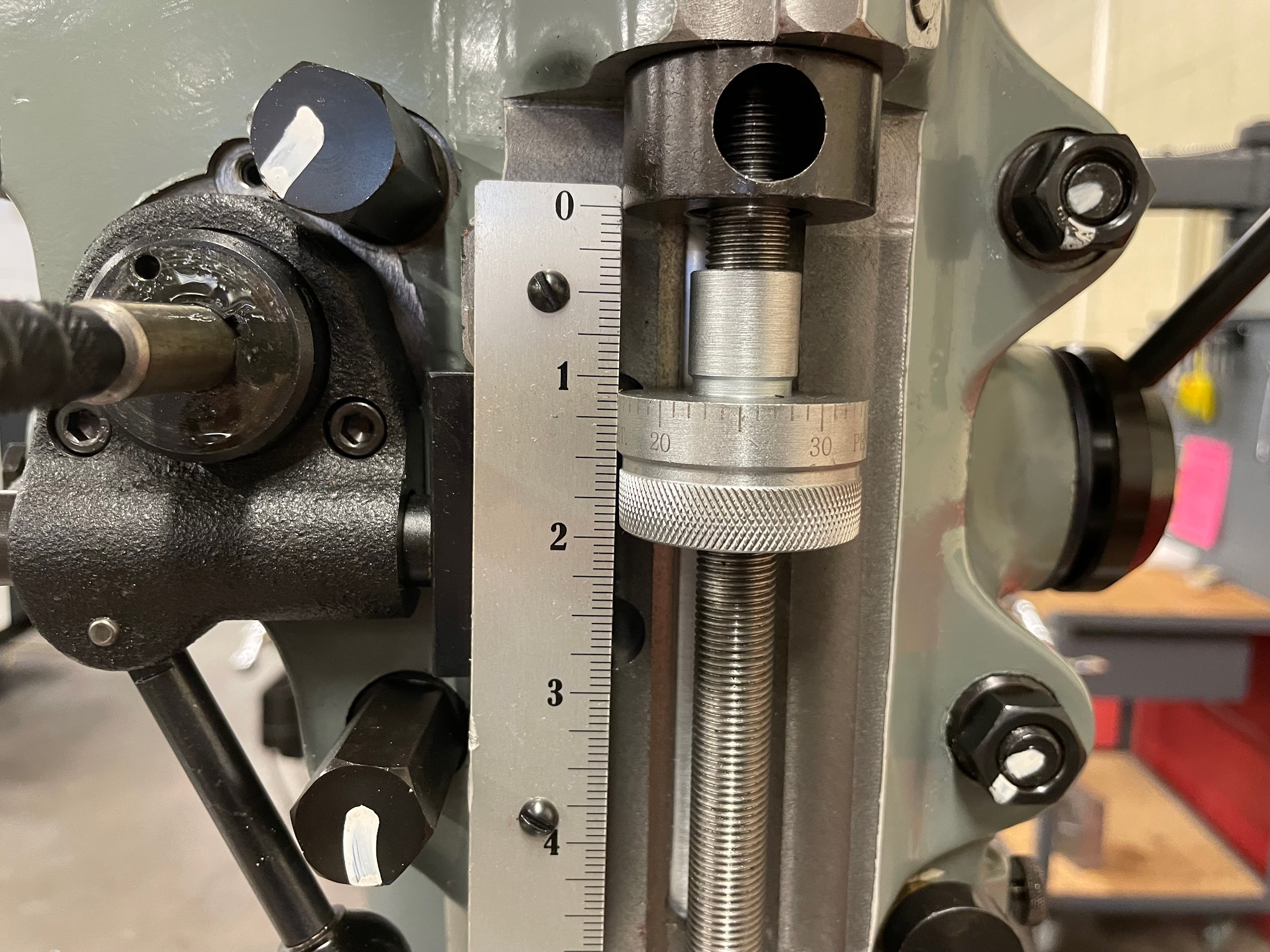
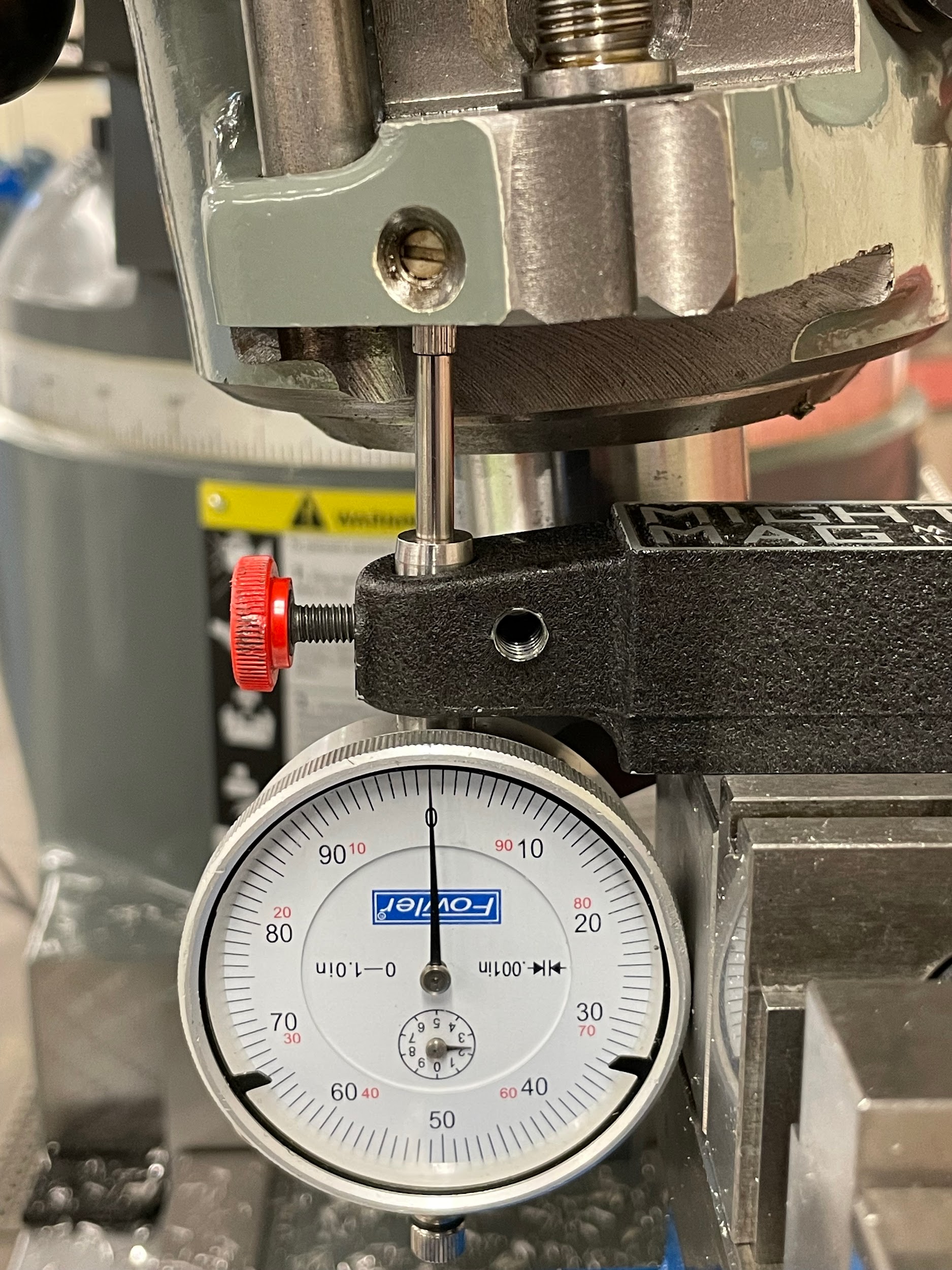
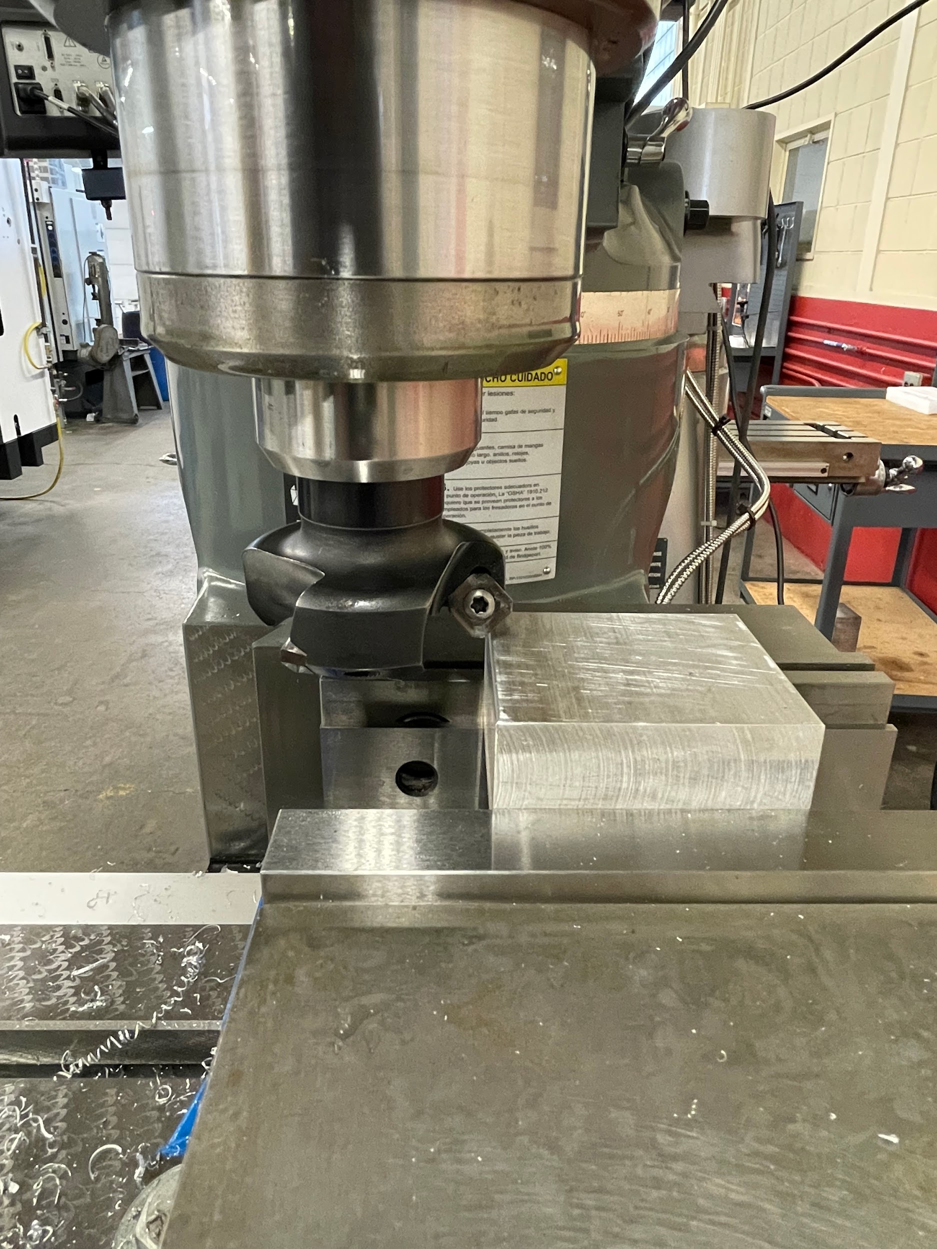
- Attach a drop indicator to the vise so that the indicator shaft is pointed vertically or horizontally at a precision surface of the head. Two examples are shown, one using the milled surface on the bottom of the head and one using the side of the quill.
- Calculate the amount of the desired leg of the triangle associated with the angular cut. In the example shown, a 6-degree angle is to be cut. The operator can use whatever intentional movement distance they like, but one that is an even number and easy to calculate is best. In this example, 1.000″ is used. The surface of the head makes up the hypotenuse, the operator moving the table or the knee makes one leg of the triangle, and the drop of the indicator makes the other leg. Knowing that the angle, and one leg are given, and the other leg is in question, the tangent formula will be used. The calculation looks like this”
Tan angl = opp/adj
Tan 6° = Z/1.000″
Tan 6° × 1.000″= Z/1.000″ × 1.000″
Tan 6° × 1.000 = Z
.105″ = Z
- Move the indicator so the shaft is depressed by at least .100 more than the amount of the calculated drop.
- Remove any backlash in the table/knee movement and zero the graduated collar.
- Zero the indicator.
- Move the table/knee by exactly 1.000.
- Read the drop in the indicator. If the drop isn’t accurate to the calculated leg, adjust the head and remeasure until the drop is within tolerance.
- Tighten the fasteners that secure the head movement to 50 ft./lbs.
- Load an end mill or face mill into the milling machine. Generally, a tool that will accomplish the cut in one pass is best.
- Calculate the spindle speed and feed rate for the tool selected.
- Turn on the spindle and adjust the speed.
- Lock the quill.
- Gently touch the tool off to the prominent corner by raising the knee.
- Zero the knee.
- Calculate the amount to be removed from the part using right angle trigonometry.
- Remove the necessary material over multiple passes using face milling cuts.
- Turn off the spindle.
- Lower the knee.
- Clean and inspect the feature.
Step 2: Loosen the fasteners that lock the movement of the head.
Step 2: Loosen the fasteners that lock the movement of the head.
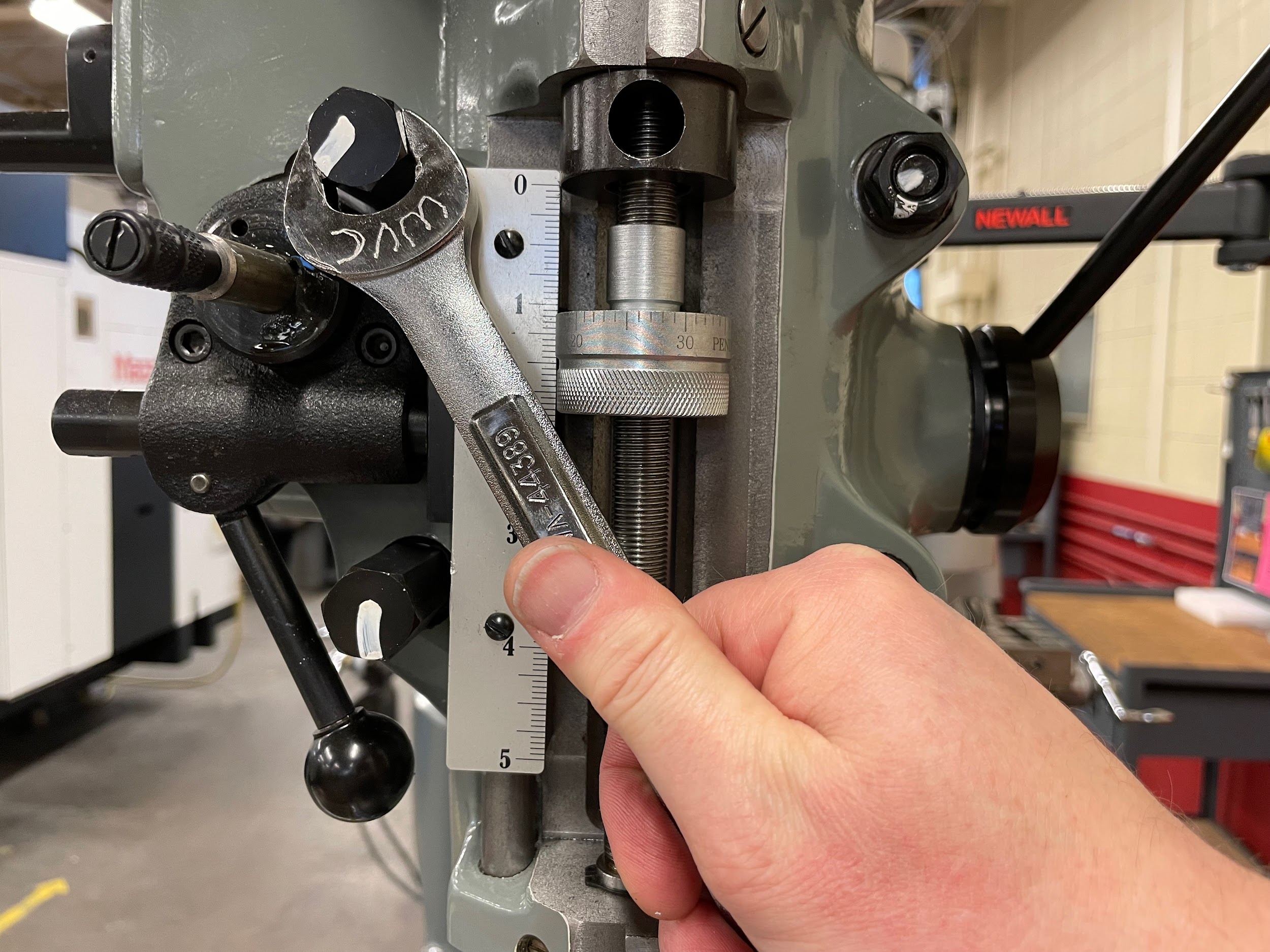
Step 3: Adjust the head to the approximate angle required.
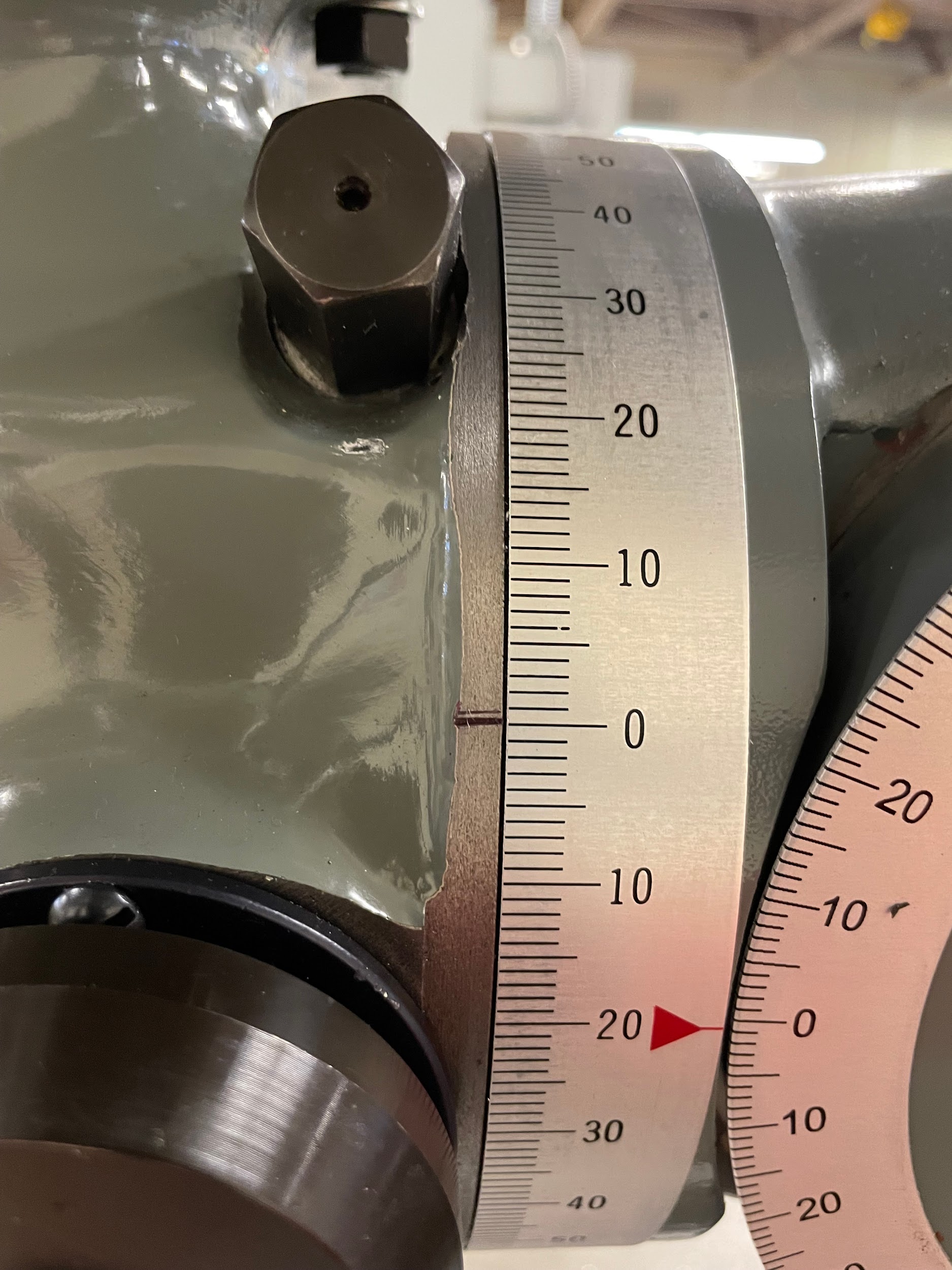
Step 3: Adjust the head to the approximate angle required.
Step 3: Adjust the head to the approximate angle required.

Step 4: Attach a drop indicator to the vise so that the indicator shaft is pointed vertically or horizontally at a precision surface of the head. Two examples are shown, one using the milled surface on the bottom of the head and one using the side of the quill.
Step 9: Move the table/knee by exactly 1.000.

Step 9: Move the table/knee by exactly 1.000.

Step 16: Gently touch the tool off to the prominent corner by raising the knee.
Step 19: Remove the necessary material over multiple passes using face milling cuts.

Step 19: Remove the necessary material over multiple passes using face milling cuts.
Step by step process for cutting 45-degree chamfer angles:
- Load the part in the vise on parallels.
- Load a chamfer mill or face mill that has a 45 degree angle into the milling machine.
- Calculate the spindle speed and feed rate for the tool selected. Remember to base the calculation on the largest diameter of the tool that will touch the material.
- Turn on the spindle and adjust the speed.
- Lock the quill.
- Gently touch the 45 degree angle of the tool off to the corner of the part by raising the knee.
- Zero the knee or zero the table movement.
- Move the tool off the work.
- Adjust the knee or the table by the amount of chamfer indicated on the print. To determine which to adjust, inspect what part of the tool angle has been touched to the part. If it is near the top of the angle, adjusting the table movement is probably the best. If it is near the bottom, raising the knee is probably best. Whichever method is employed, the length of the chamfer on the tool cannot be overrun or an undesirable step will result.
- Lock the table.
- Cut the chamfer by moving the saddle.
- Turn off the spindle.
- Lower the knee.
- Clean and inspect the feature.
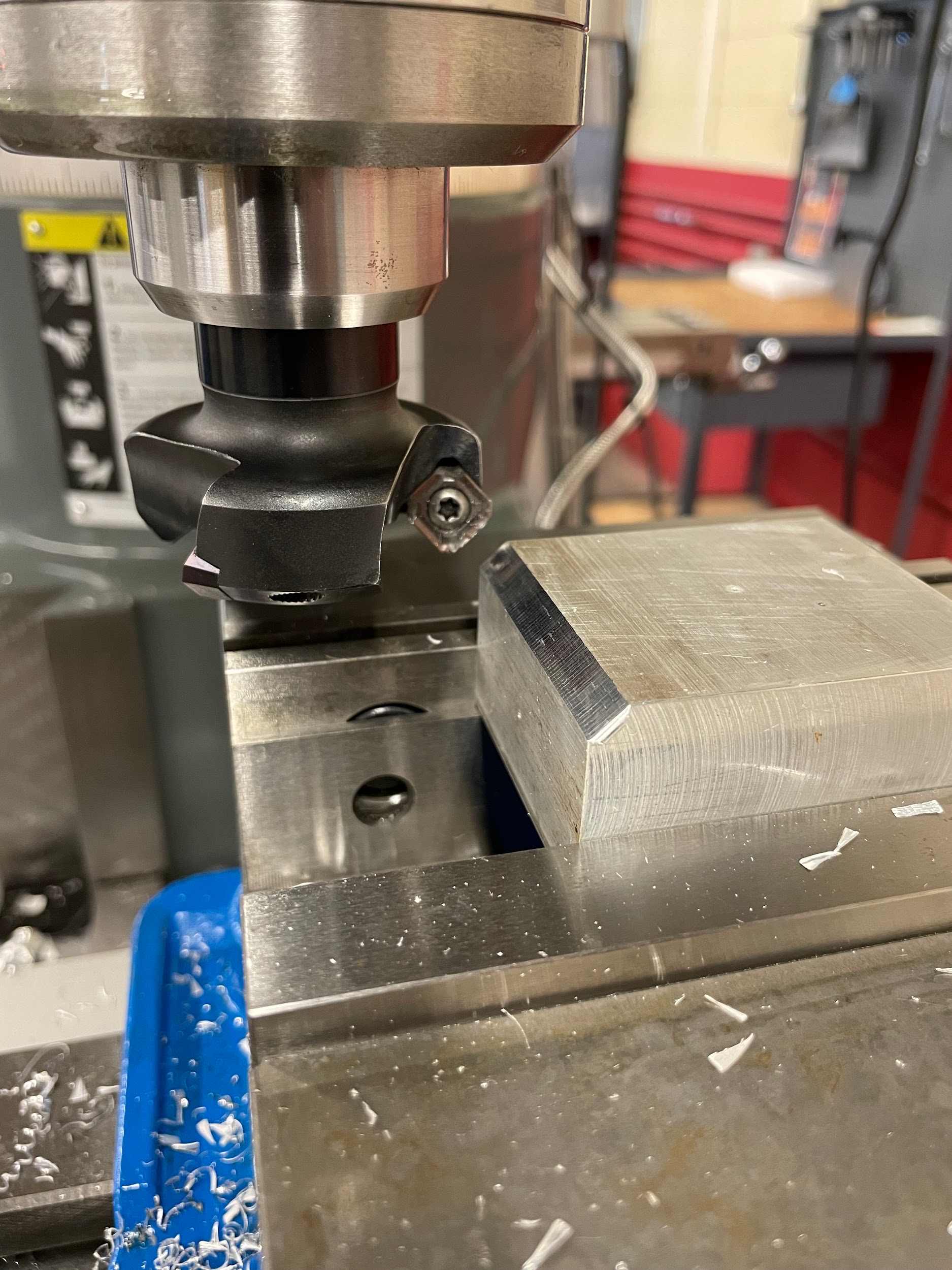
Step 1-2: Load the part in the vise on parallels. Load a chamfer mill or face mill that has a 45 degree angle into the milling machine.
Step 6: Gently touch the 45 degree angle of the tool off to the corner of the part by raising the knee.
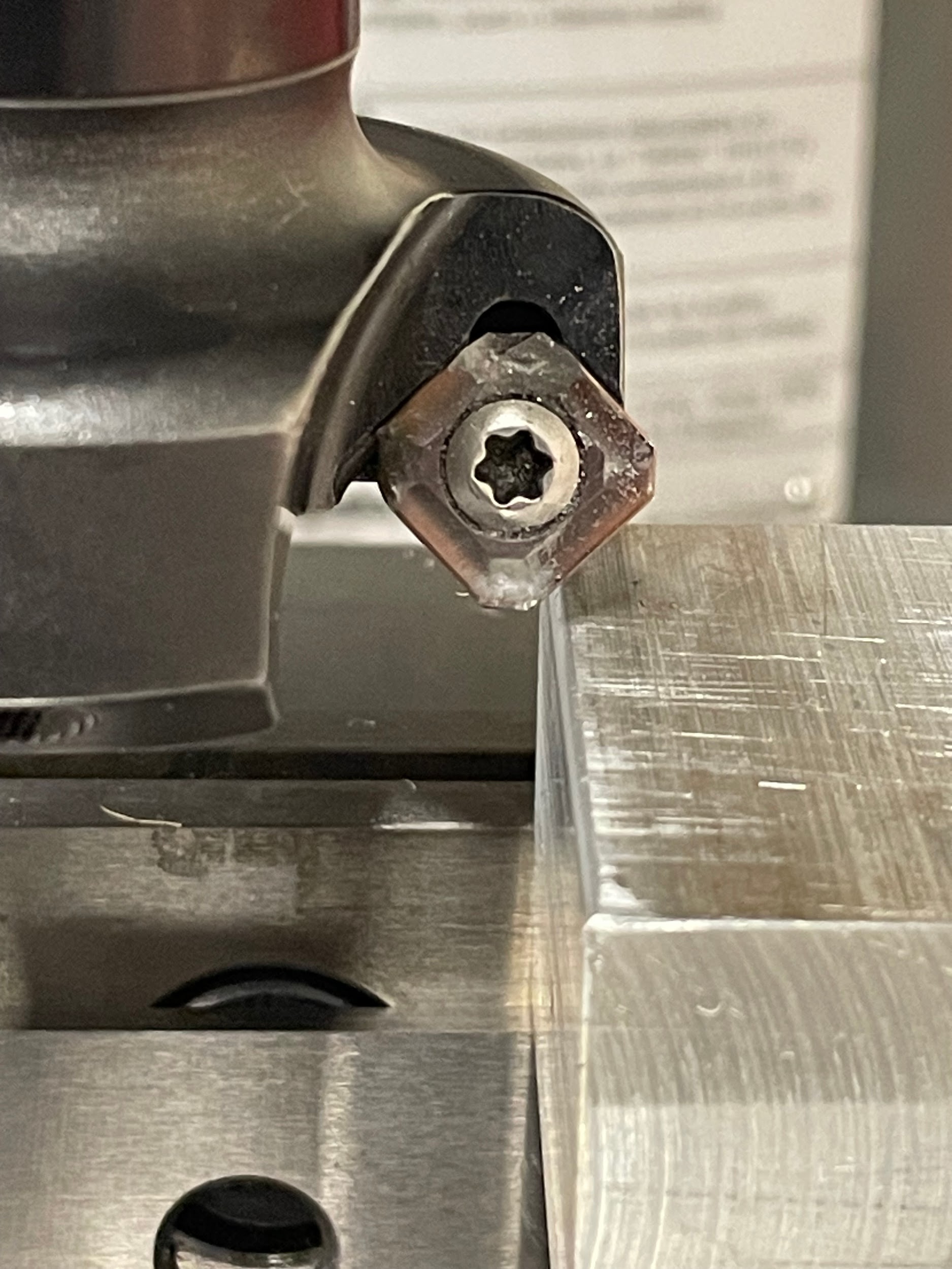
Step 6: Gently touch the 45 degree angle of the tool off to the corner of the part by raising the knee.

Step 11: Cut the chamfer by moving the saddle.

Step 11: Cut the chamfer by moving the saddle.
Author’s Tip
I am often machining a one-off part that needs an angular cut. I prefer the simplicity of holding the part at an angle in a vise and applying face mill style cuts, versus making a fixture or adjusting the milling head. It just makes sense to use the most time-saving option. However, instead of using parallels, I will often use an indicator and math to set the part in the vise at the correct angle. Sometimes I do this because no parallels exist at the angle I am attempting to cut, or maybe I am needing an angle that is more precise than the parallels are capable of holding. To use this method, you must first calculate a measurable scenario using the angle you wish to cut. This scenario will change based on the size of the part. I generally use the largest sizes I can because they will give the most accuracy. For instance, if my part is 1-½” long, I would use 1″ or larger for my measuring scenario versus ¼”. I will use the angle desired and the selected leg length in order to calculate the length of the other leg. After this calculation, I install a drop indicator on the milling spindle and touch it near the top of my part that is set at approximately the required level. I then zero the indicator and zero the table movement. Then, I run the indicator along the part at the exact distance I used as the long leg in the calculation. Next, I read the indicator; this represents the length of the short leg. Using only a .001″ resolution indicator, you can get a very accurate result this way, depending on the length you are allowed to use as the long leg.
Attributions
- Figure 9.190: Finished angular cut by Micky R. Jennings, courtesy of Wenatchee Valley College, for WA Open ProfTech, © SBCTC, CC BY 4.0
- Figure 9.191: Precision angle block by Micky R. Jennings, courtesy of Wenatchee Valley College, for WA Open ProfTech, © SBCTC, CC BY 4.0
- Figure 9.192: Precision angle block in a vise by Micky R. Jennings, courtesy of Wenatchee Valley College, for WA Open ProfTech, © SBCTC, CC BY 4.0
- Figure 9.193: Workpiece at an angle by Micky R. Jennings, courtesy of Wenatchee Valley College, for WA Open ProfTech, © SBCTC, CC BY 4.0
- Figure 9.194: Workpiece at an angle by Micky R. Jennings, courtesy of Wenatchee Valley College, for WA Open ProfTech, © SBCTC, CC BY 4.0
- Figure 9.195: Drop indicator on milling head by Micky R. Jennings, courtesy of Wenatchee Valley College, for WA Open ProfTech, © SBCTC, CC BY 4.0
- Figure 9.196: Drop indicator zeroed by Micky R. Jennings, courtesy of Wenatchee Valley College, for WA Open ProfTech, © SBCTC, CC BY 4.0
- Video 9.57: Micky R. Jennings, courtesy of Wenatchee Valley College, for WA Open ProfTech, © SBCTC, CC BY 4.0
- Video 9.58: Micky R. Jennings, courtesy of Wenatchee Valley College, for WA Open ProfTech, © SBCTC, CC BY 4.0
- Figure 9.197: Touching face mill to corner by Micky R. Jennings, courtesy of Wenatchee Valley College, for WA Open ProfTech, © SBCTC, CC BY 4.0
- Video 9.59: Micky R. Jennings, courtesy of Wenatchee Valley College, for WA Open ProfTech, © SBCTC, CC BY 4.0
- Figure 9.198: Angle cut finished by Micky R. Jennings, courtesy of Wenatchee Valley College, for WA Open ProfTech, © SBCTC, CC BY 4.0
- Figure 9.199: Tilt securing nuts by Micky R. Jennings, courtesy of Wenatchee Valley College, for WA Open ProfTech, © SBCTC, CC BY 4.0
- Figure 9.200: Adjusting the tilt nuts by Micky R. Jennings, courtesy of Wenatchee Valley College, for WA Open ProfTech, © SBCTC, CC BY 4.0
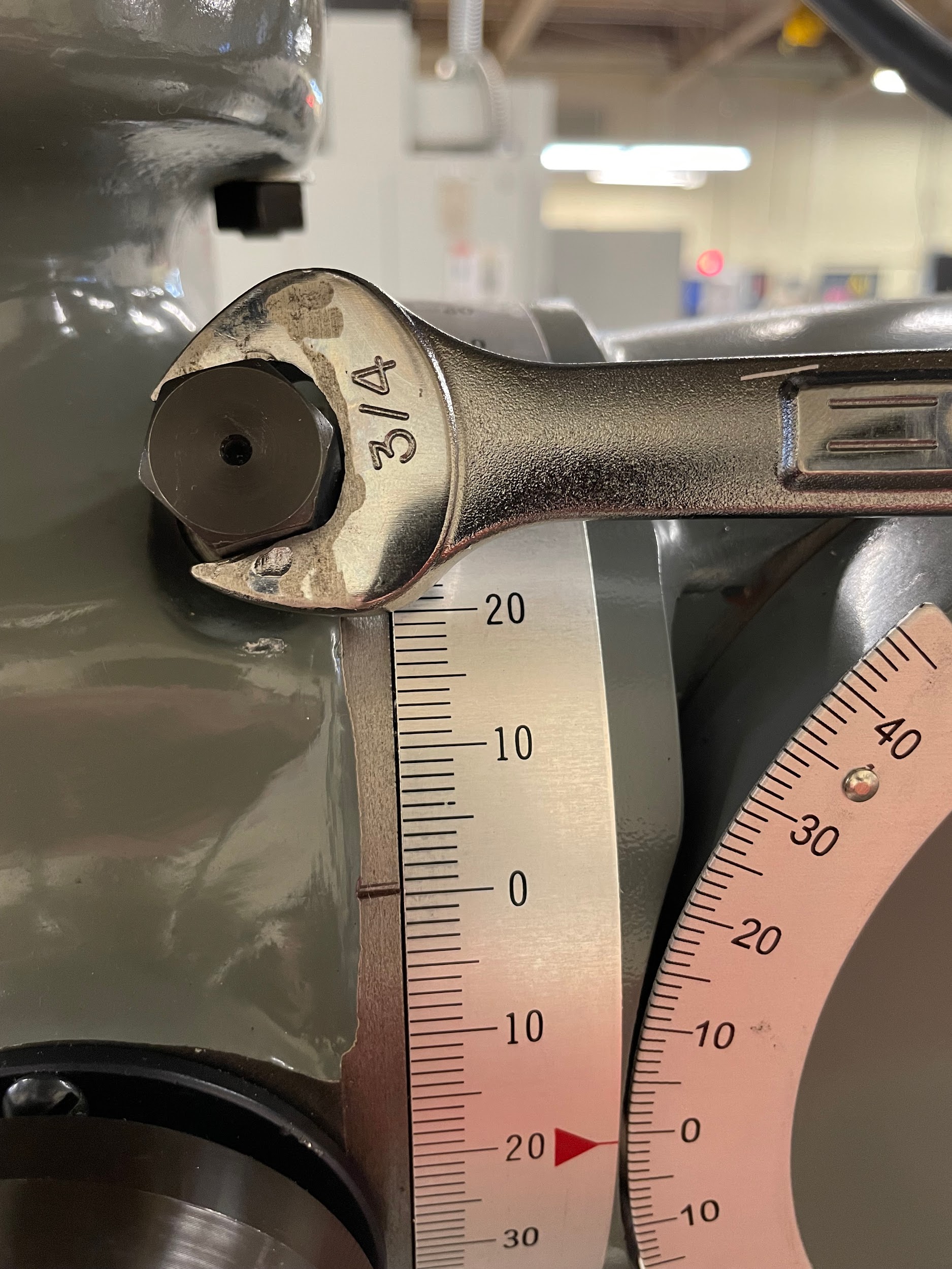
- Figure 9.201: Tilt scale and worm screw adjustment hex by Micky R. Jennings, courtesy of Wenatchee Valley College, for WA Open ProfTech, © SBCTC, CC BY 4.0
- Figure 9.202: Adjusting head tilt by Micky R. Jennings, courtesy of Wenatchee Valley College, for WA Open ProfTech, © SBCTC, CC BY 4.0
- Video 9.60: Micky R. Jennings, courtesy of Wenatchee Valley College, for WA Open ProfTech, © SBCTC, CC BY 4.0
- Figure 9.203: Indicating bottom of head by Micky R. Jennings, courtesy of Wenatchee Valley College, for WA Open ProfTech, © SBCTC, CC BY 4.0
- Video 9.61: Micky R. Jennings, courtesy of Wenatchee Valley College, for WA Open ProfTech, © SBCTC, CC BY 4.0
- Video 9.62: Micky R. Jennings, courtesy of Wenatchee Valley College, for WA Open ProfTech, © SBCTC, CC BY 4.0
- Figure 9.204: Indicating quill by Micky R. Jennings, courtesy of Wenatchee Valley College, for WA Open ProfTech, © SBCTC, CC BY 4.0
- Video 9.63: Micky R. Jennings, courtesy of Wenatchee Valley College, for WA Open ProfTech, © SBCTC, CC BY 4.0
- Video 9.64: Micky R. Jennings, courtesy of Wenatchee Valley College, for WA Open ProfTech, © SBCTC, CC BY 4.0
- Figure 9.205: Touching face mill to corner by Micky R. Jennings, courtesy of Wenatchee Valley College, for WA Open ProfTech, © SBCTC, CC BY 4.0
- Video 9.65: Micky R. Jennings, courtesy of Wenatchee Valley College, for WA Open ProfTech, © SBCTC, CC BY 4.0
- Figure 9.206: Angle cut finished 2 by Micky R. Jennings, courtesy of Wenatchee Valley College, for WA Open ProfTech, © SBCTC, CC BY 4.0
- Figure 9.207: Material and tool loaded by Micky R. Jennings, courtesy of Wenatchee Valley College, for WA Open ProfTech, © SBCTC, CC BY 4.0
- Figure 9.208: Touching off the angle of the insert by Micky R. Jennings, courtesy of Wenatchee Valley College, for WA Open ProfTech, © SBCTC, CC BY 4.0
- Video 9.66: Micky R. Jennings, courtesy of Wenatchee Valley College, for WA Open ProfTech, © SBCTC, CC BY 4.0
- Video 9.67: Micky R. Jennings, courtesy of Wenatchee Valley College, for WA Open ProfTech, © SBCTC, CC BY 4.0
- Figure 9.209: Angle cut finished by Micky R. Jennings, courtesy of Wenatchee Valley College, for WA Open ProfTech, © SBCTC, CC BY 4.0
The process of using milling cutters to create angled features on a workpiece.
