9.17 Boring
Micky R. Jennings
Boring is the process of enlarging a previously drilled hole. This task is typically done using a tool called a boring head. Boring a hole is often used when a straighter, more accurate hole is needed, or a larger hole is required than those created by a twist drill. Unlike most hole-making procedures that can walk as the cut is being made because of tool flexibility, a bored hole is straight and true to the spindle axis of the milling machine.
Step by step process for boring:
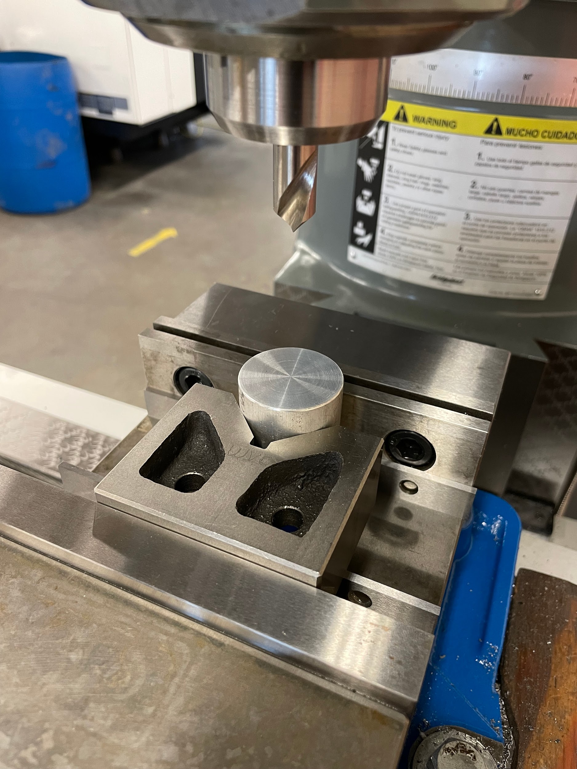
- Edge find and position the machine at the center of the hole.
- Lock the table and saddle movement.
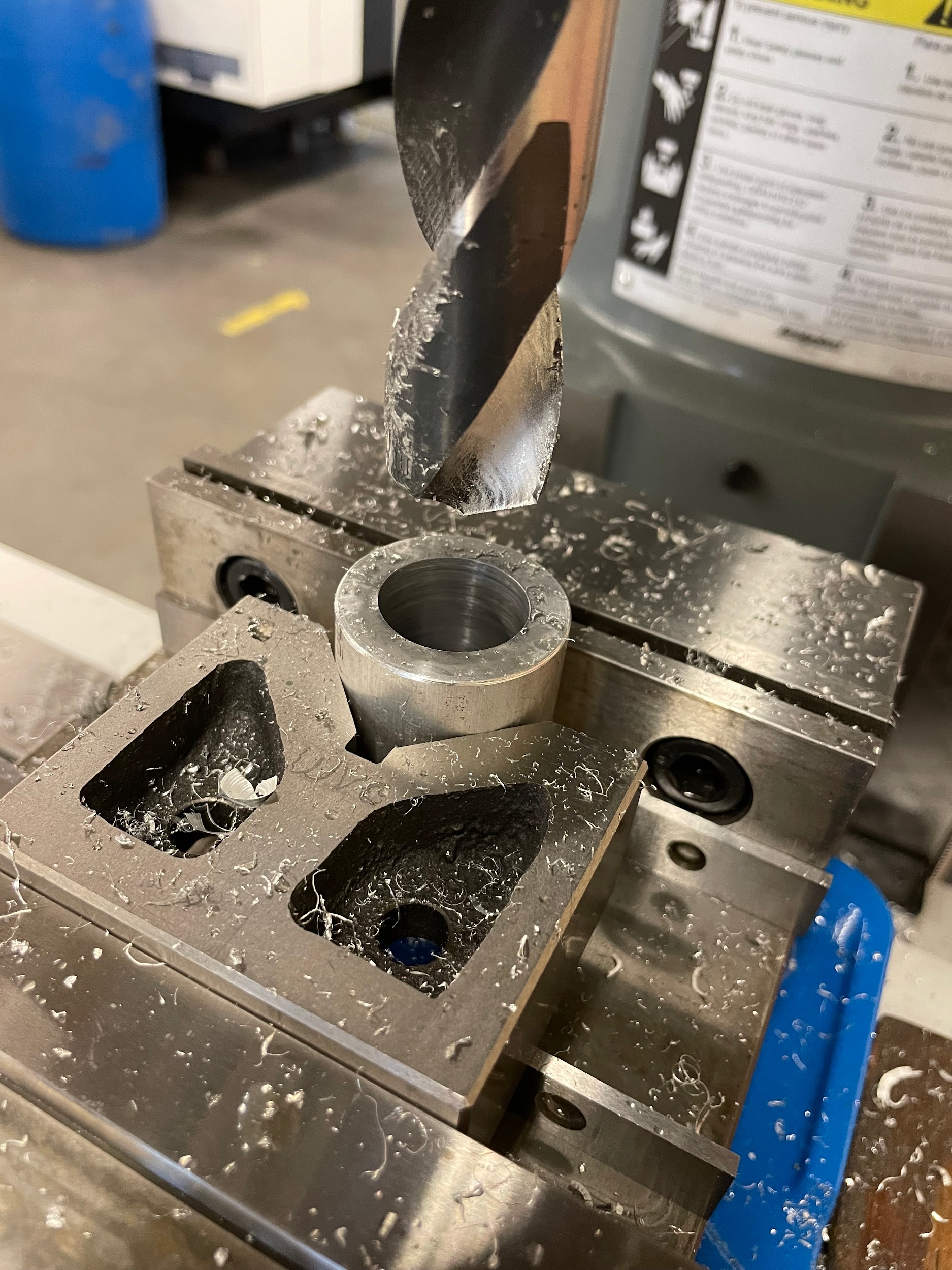
- Drill the largest hole possible at the center of the bore layout. Removing material through drilling is much quicker than boring.
- Install a boring head into the milling machine.
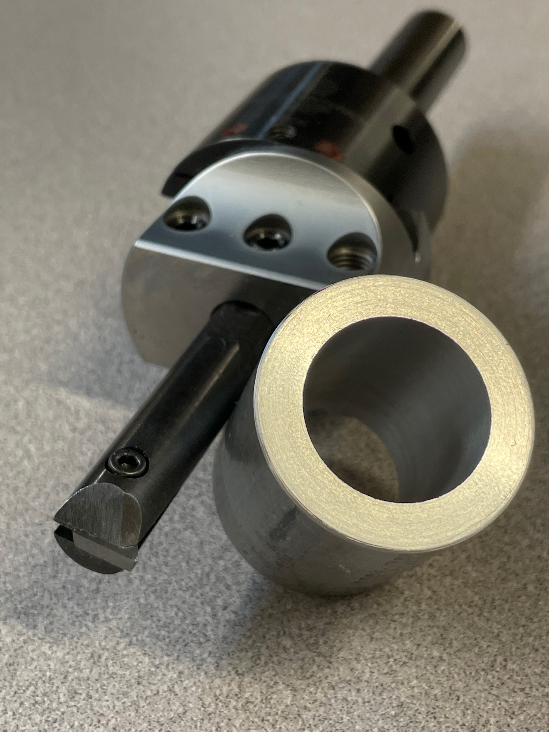
- Install a boring bar into the appropriate hole in the boring head and secure it with the set screw.
- Raise the knee to where, when the quill is at the top of travel, there is about ½ of space between the tool and the work.
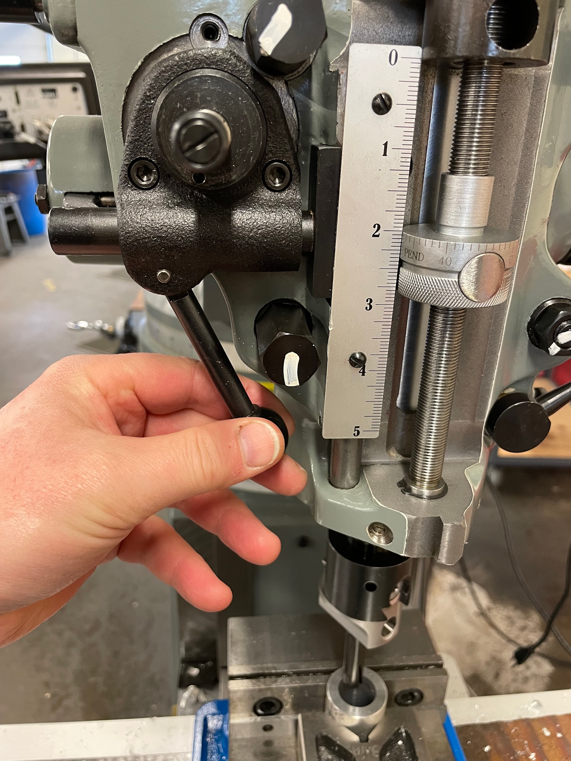
- Pull the quill handle down to where the tool is sticking through the hole by about ⅛” and set the quill stop.
- Adjust the boring head so that the cutting edge of the bar slightly touches the drilled hole by loosening the lock on the dovetail and turning the hex in the dial face.
- Adjust the boring head to take an initial cut. Depths of cut for a boring head will vary based on material, cutter, and conditions. Roughing cuts may be .020-.050, whereas finishing cuts may be .003-.010 or less.
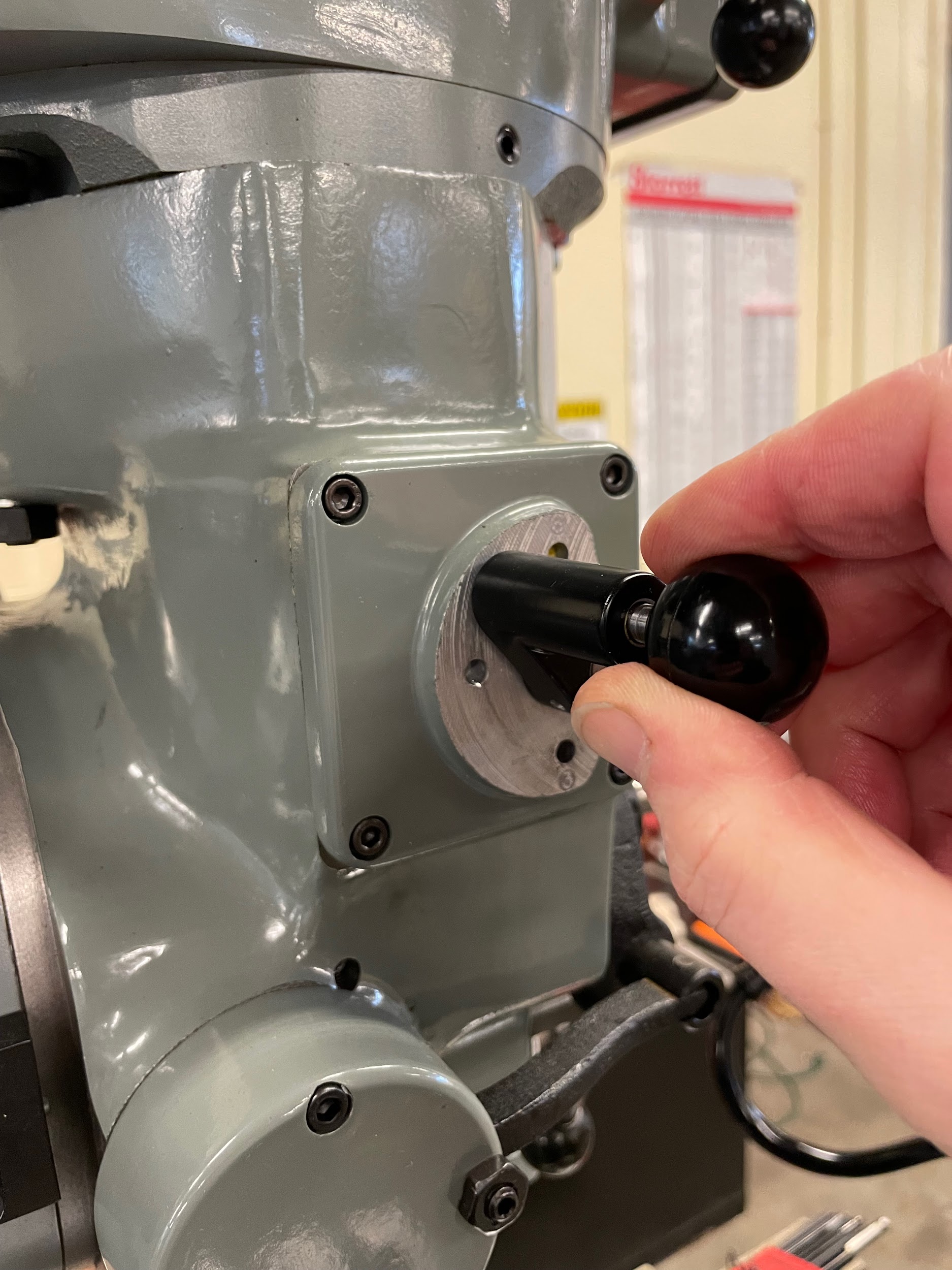
- Move the quill feed engagement knob, located on the right side of the head, from disengage to engage. This can only be accomplished while the spindle is off.
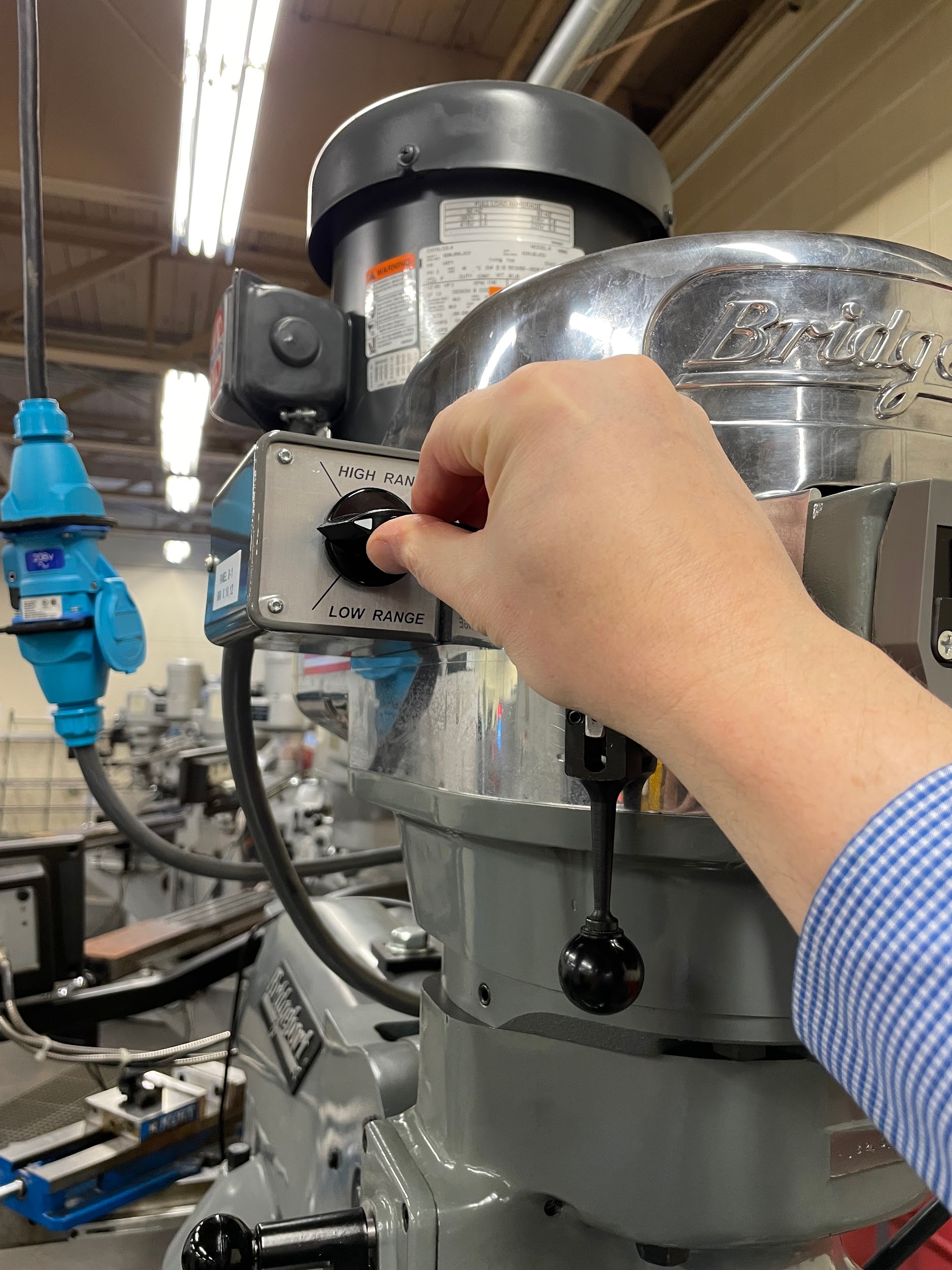
- Select the quill feed increment, in IPR, on the left side of the mill. Some are labeled .006, .003, and .0015, but some are just labeled high, medium, and low. This can also only be accomplished while the spindle is off.
- Lightly set the quill lock so the quill doesn’t automatically spring up on its own, yet it moves as freely as possible.
- Calculate the spindle speed for the tool using the finished diameter of the hole.
- Lube the hole.
- Turn the spindle on and adjust the speed.
- In the middle of the quill fine feed handwheel, pull out or push in the engagement pin. This will set the quill feed to move either up or down.
- Now pull and briefly hold the quill feed lever on the left side of the head to start the automatic quill engagement.
- The machine will automatically feed the tool through the hole until it reaches the stop on the opposite side. At that point, the quill feed will disengage.
- Turn off the spindle.
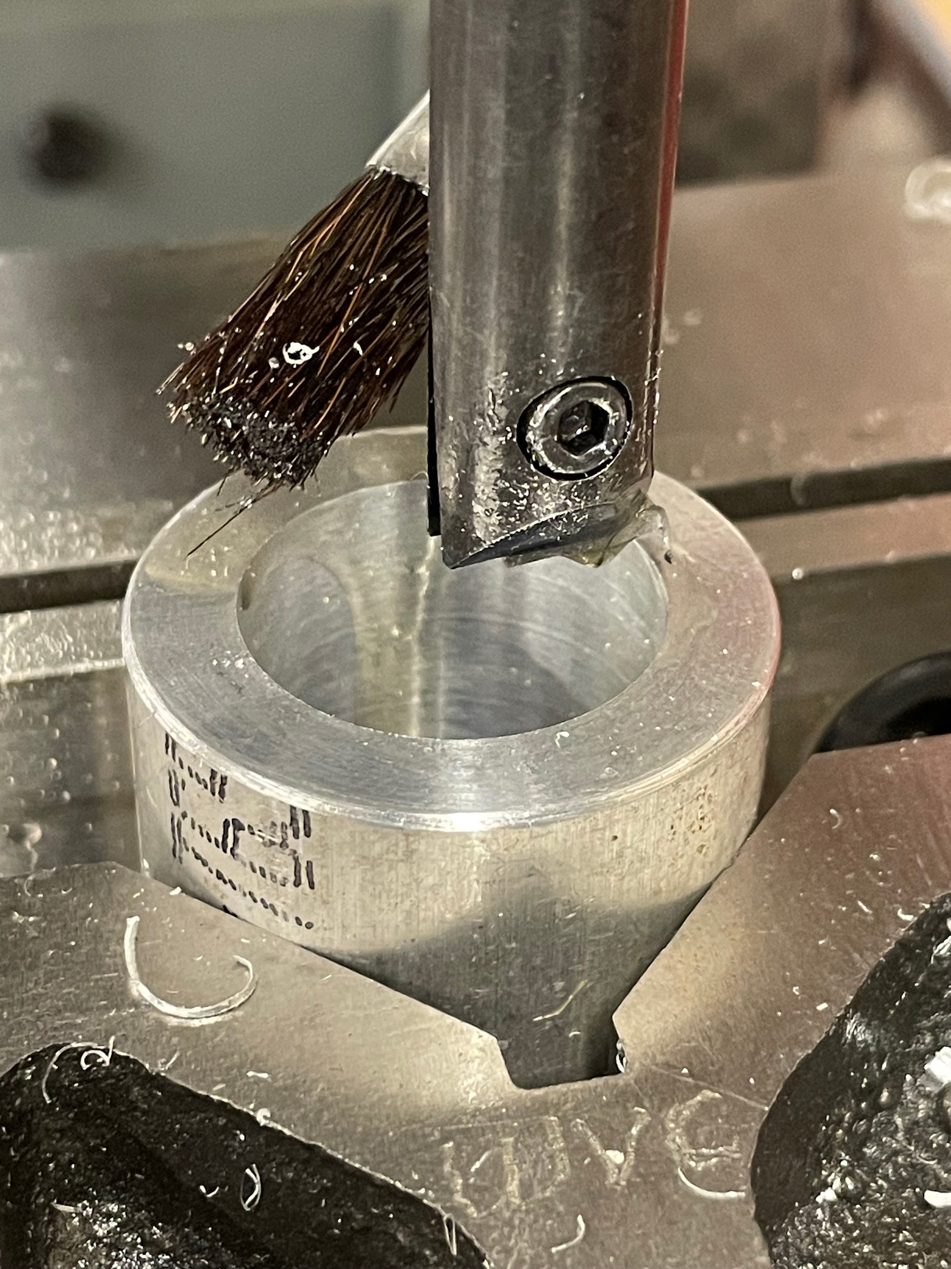
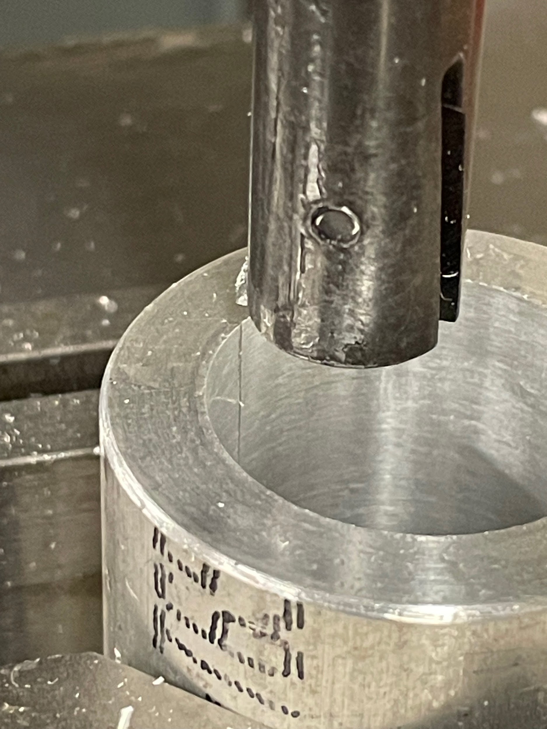
- Manually pull the quill up through the hole. Pulling out in this fashion will keep the tool from cutting extra material on the upstroke and potentially oversizing the hole. Pulling out in this way will also indicate the amount of bar deflection that occurred during roughing passes when examining the scored line on the side of the bore. On a finish pass, the machine should be moved, or the head adjusted so scoring is absent.
- Measure the bored hole and calculate remaining material removal.
- Adjust the boring head and take additional cuts to bring the bore to size.
- Clean and inspect the feature.
- When finished, return the quill feed engagement pin and knob to their disengaged positions.
- Remove the boring head from the spindle, clean, and return it to storage.
Step 3: Drill the largest hole possible at the center of the bore layout. Removing material through drilling is much quicker than boring.
Step 3: Drill the largest hole possible at the center of the bore layout. Removing material through drilling is much quicker than boring.
Step 3: Drill the largest hole possible at the center of the bore layout. Removing material through drilling is much quicker than boring.


Step 3: Drill the largest hole possible at the center of the bore layout. Removing material through drilling is much quicker than boring.

Step 3: Drill the largest hole possible at the center of the bore layout. Removing material through drilling is much quicker than boring.
Step 4: Install a boring head into the milling machine.
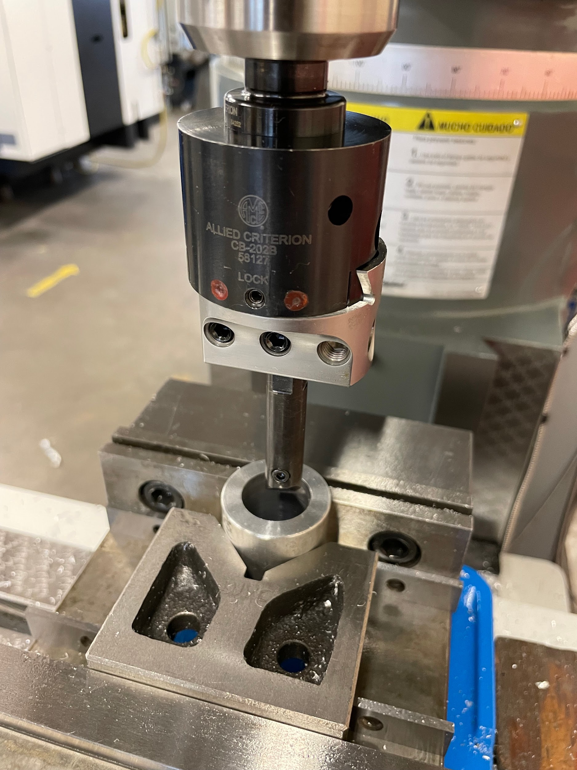
Step 7: Pull the quill handle down to where the tool is sticking through the hole by about ⅛” and set the quill stop.
Step 7: Pull the quill handle down to where the tool is sticking through the hole by about ⅛” and set the quill stop.

Step 8: Adjust the boring head so that the cutting edge of the bar slightly touches the drilled hole by loosening the lock on the dovetail and turning the hex in the dial face.

Step 8: Adjust the boring head so that the cutting edge of the bar slightly touches the drilled hole by loosening the lock on the dovetail and turning the hex in the dial face.

Step 9: Adjust the boring head to take an initial cut. Depths of cut for a boring head will vary based on material, cutter, and conditions. Roughing cuts may be .020-.050, whereas finishing cuts may be .003-.010 or less.
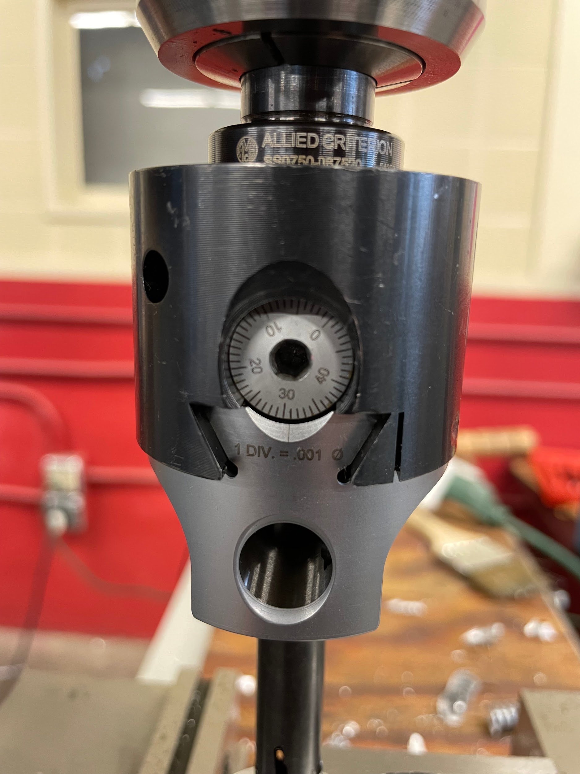
Step 9: Adjust the boring head to take an initial cut. Depths of cut for a boring head will vary based on material, cutter, and conditions. Roughing cuts may be .020-.050, whereas finishing cuts may be .003-.010 or less.

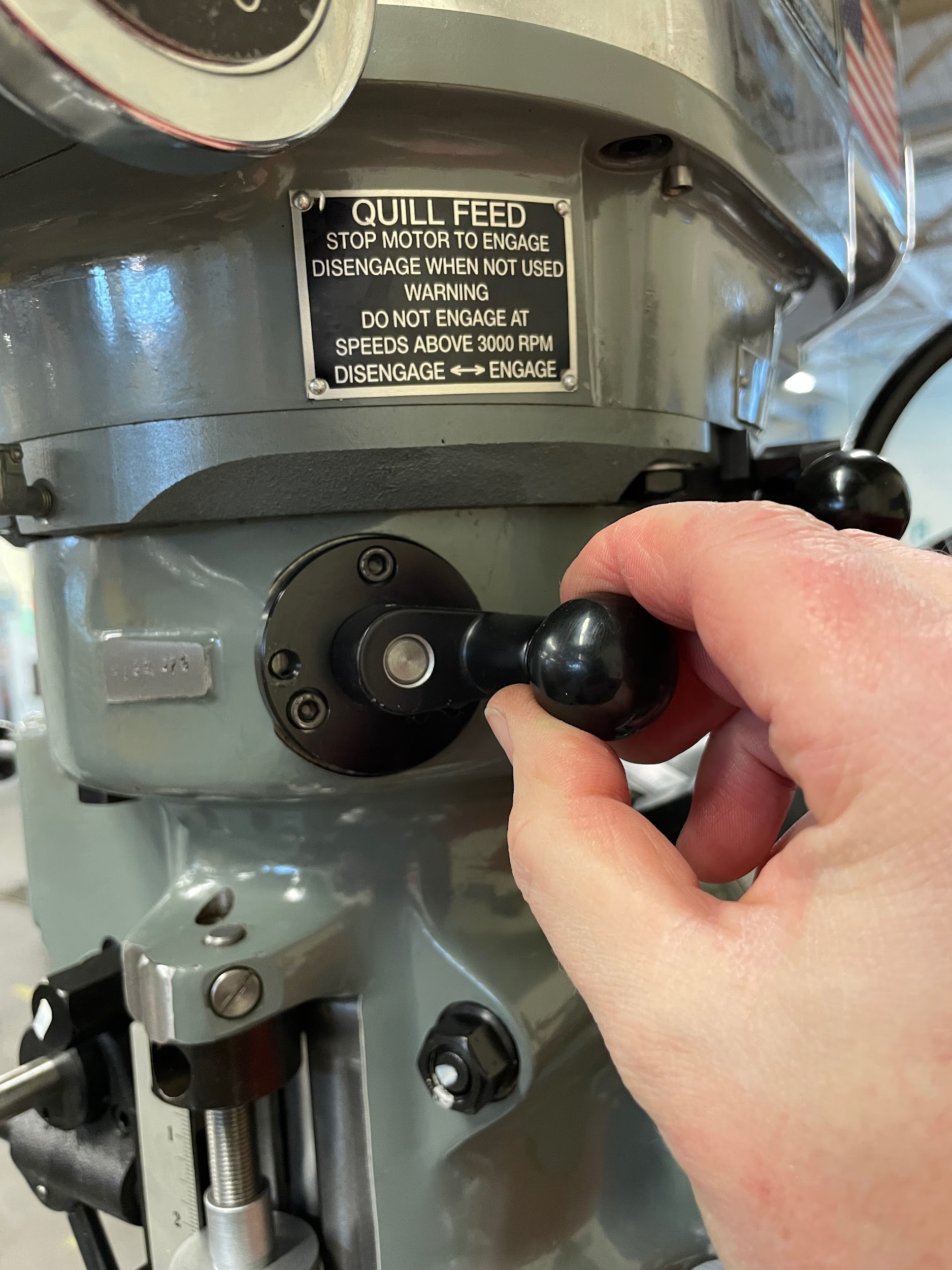
Step 10: Move the quill feed engagement knob, located on the right side of the head, from disengage to engage. This can only be accomplished while the spindle is off.
Step 11: Select the quill feed increment, in IPR, on the left side of the mill. Some are labeled .006, .003, and .0015, but some are just labeled high, medium, and low. This can also only be accomplished while the spindle is off.
Step 14: Lube the hole.

Step 14: Lube the hole.
Step 15: Turn the spindle on and adjust the speed.
Step 16: In the middle of the quill fine feed handwheel, pull out or push in the engagement pin. This will set the quill feed to move either up or down.
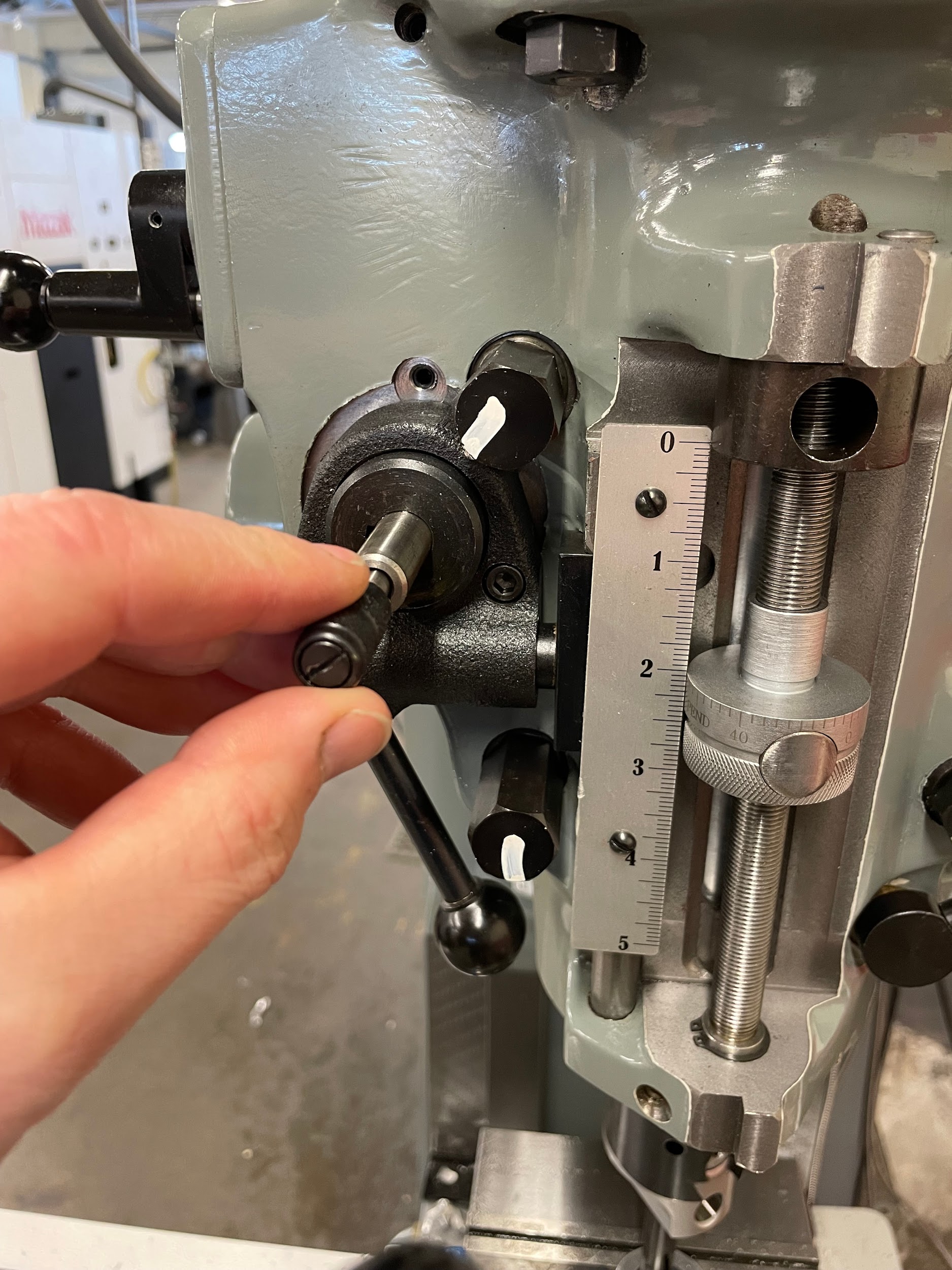
Step 16: In the middle of the quill fine feed handwheel, pull out or push in the engagement pin. This will set the quill feed to move either up or down.

Step 17: Now pull and briefly hold the quill feed lever on the left side of the head to start the automatic quill engagement.
Step 17-20: Now pull and briefly hold the quill feed lever on the left side of the head to start the automatic quill engagement. The machine will automatically feed the tool through the hole until it reaches the stop on the opposite side. At that point, the quill feed will disengage. Turn off the spindle. Manually pull the quill up through the hole. Pulling out in this fashion will keep the tool from cutting extra material on the upstroke and potentially oversizing the hole. Pulling out in this way will also indicate the amount of bar deflection that occurred during roughing passes when examining the scored line on the side of the bore. On a finish pass, the machine should be moved, or the head adjusted so scoring is absent.

Step 18: The machine will automatically feed the tool through the hole until it reaches the stop on the opposite side. At that point, the quill feed will disengage.

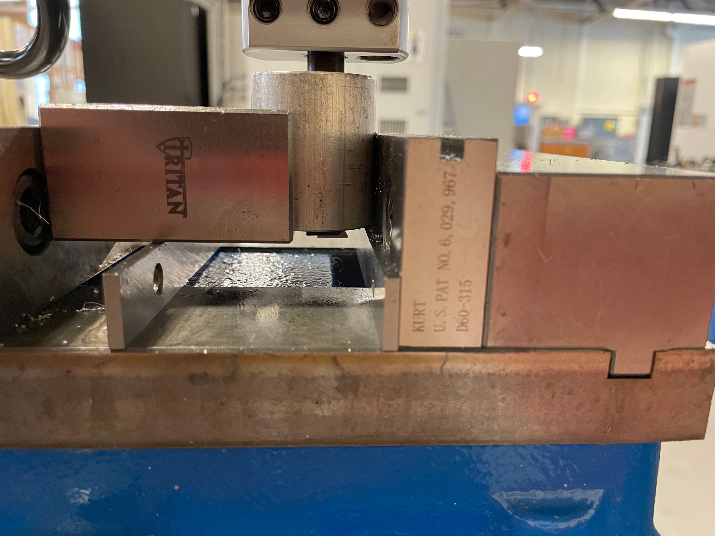
Step 20: Manually pull the quill up through the hole. Pulling out in this fashion will keep the tool from cutting extra material on the upstroke and potentially oversizing the hole. Pulling out in this way will also indicate the amount of bar deflection that occurred during roughing passes when examining the scored line on the side of the bore. On a finish pass, the machine should be moved, or the head adjusted so scoring is absent.

Step 20: Manually pull the quill up through the hole. Pulling out in this fashion will keep the tool from cutting extra material on the upstroke and potentially oversizing the hole. Pulling out in this way will also indicate the amount of bar deflection that occurred during roughing passes when examining the scored line on the side of the bore. On a finish pass, the machine should be moved, or the head adjusted so scoring is absent.
Step 23: Clean and inspect the feature.

Attributions
- Figure 9.216: Finished bored hole by Micky R. Jennings, courtesy of Wenatchee Valley College, for WA Open ProfTech, © SBCTC, CC BY 4.0
- Figure 9.217: Spot a hole by Micky R. Jennings, courtesy of Wenatchee Valley College, for WA Open ProfTech, © SBCTC, CC BY 4.0
- Figure 9.218: Lube the work by Micky R. Jennings, courtesy of Wenatchee Valley College, for WA Open ProfTech, © SBCTC, CC BY 4.0
- Video 9.73: Micky R. Jennings, courtesy of Wenatchee Valley College, for WA Open ProfTech, © SBCTC, CC BY 4.0
- Video 9.74: Micky R. Jennings, courtesy of Wenatchee Valley College, for WA Open ProfTech, © SBCTC, CC BY 4.0
- Video 9.75: Micky R. Jennings, courtesy of Wenatchee Valley College, for WA Open ProfTech, © SBCTC, CC BY 4.0
- Figure 9.219: Hole drilling by Micky R. Jennings, courtesy of Wenatchee Valley College, for WA Open ProfTech, © SBCTC, CC BY 4.0
- Figure 9.220: Installing a boring head by Micky R. Jennings, courtesy of Wenatchee Valley College, for WA Open ProfTech, © SBCTC, CC BY 4.0
- Figure 9.221: Boring depth by Micky R. Jennings, courtesy of Wenatchee Valley College, for WA Open ProfTech, © SBCTC, CC BY 4.0
- Video 9.76: Micky R. Jennings, courtesy of Wenatchee Valley College, for WA Open ProfTech, © SBCTC, CC BY 4.0
- Figure 9.222: Adjusting the boring head lock by Micky R. Jennings, courtesy of Wenatchee Valley College, for WA Open ProfTech, © SBCTC, CC BY 4.0
- Video 9.77: Micky R. Jennings, courtesy of Wenatchee Valley College, for WA Open ProfTech, © SBCTC, CC BY 4.0
- Figure 9.223: Boring head dovetail and dial by Micky R. Jennings, courtesy of Wenatchee Valley College, for WA Open ProfTech, © SBCTC, CC BY 4.0
- Video 9.78: Micky R. Jennings, courtesy of Wenatchee Valley College, for WA Open ProfTech, © SBCTC, CC BY 4.0
- Figure 9.224: Quill feed engagement by Micky R. Jennings, courtesy of Wenatchee Valley College, for WA Open ProfTech, © SBCTC, CC BY 4.0
- Figure 9.225: Quill feed rate by Micky R. Jennings, courtesy of Wenatchee Valley College, for WA Open ProfTech, © SBCTC, CC BY 4.0
- Video 9.79: Micky R. Jennings, courtesy of Wenatchee Valley College, for WA Open ProfTech, © SBCTC, CC BY 4.0
- Figure 9.226: Lubing the hole by Micky R. Jennings, courtesy of Wenatchee Valley College, for WA Open ProfTech, © SBCTC, CC BY 4.0
- Figure 9.227: Spindle on by Micky R. Jennings, courtesy of Wenatchee Valley College, for WA Open ProfTech, © SBCTC, CC BY 4.0
- Figure 9.228: Quill feed direction by Micky R. Jennings, courtesy of Wenatchee Valley College, for WA Open ProfTech, © SBCTC, CC BY 4.0
- Video 9.80: Micky R. Jennings, courtesy of Wenatchee Valley College, for WA Open ProfTech, © SBCTC, CC BY 4.0
- Figure 9.229: Activating the quill feed by Micky R. Jennings, courtesy of Wenatchee Valley College, for WA Open ProfTech, © SBCTC, CC BY 4.0
- Video 9.81: Micky R. Jennings, courtesy of Wenatchee Valley College, for WA Open ProfTech, © SBCTC, CC BY 4.0
- Video 9.82: Micky R. Jennings, courtesy of Wenatchee Valley College, for WA Open ProfTech, © SBCTC, CC BY 4.0
- Video 9.83: Micky R. Jennings, courtesy of Wenatchee Valley College, for WA Open ProfTech, © SBCTC, CC BY 4.0
- Figure 9.230: Pull bar out of hole by Micky R. Jennings, courtesy of Wenatchee Valley College, for WA Open ProfTech, © SBCTC, CC BY 4.0
- Figure 9.231: Finished bored hole by Micky R. Jennings, courtesy of Wenatchee Valley College, for WA Open ProfTech, © SBCTC, CC BY 4.0
A cutting operation that uses a single point cutting tool (boring bar) to produce an internal conical, or cylindrical feature by enlarging an existing opening in a workpiece.
