9.19 Indexing
Micky R. Jennings
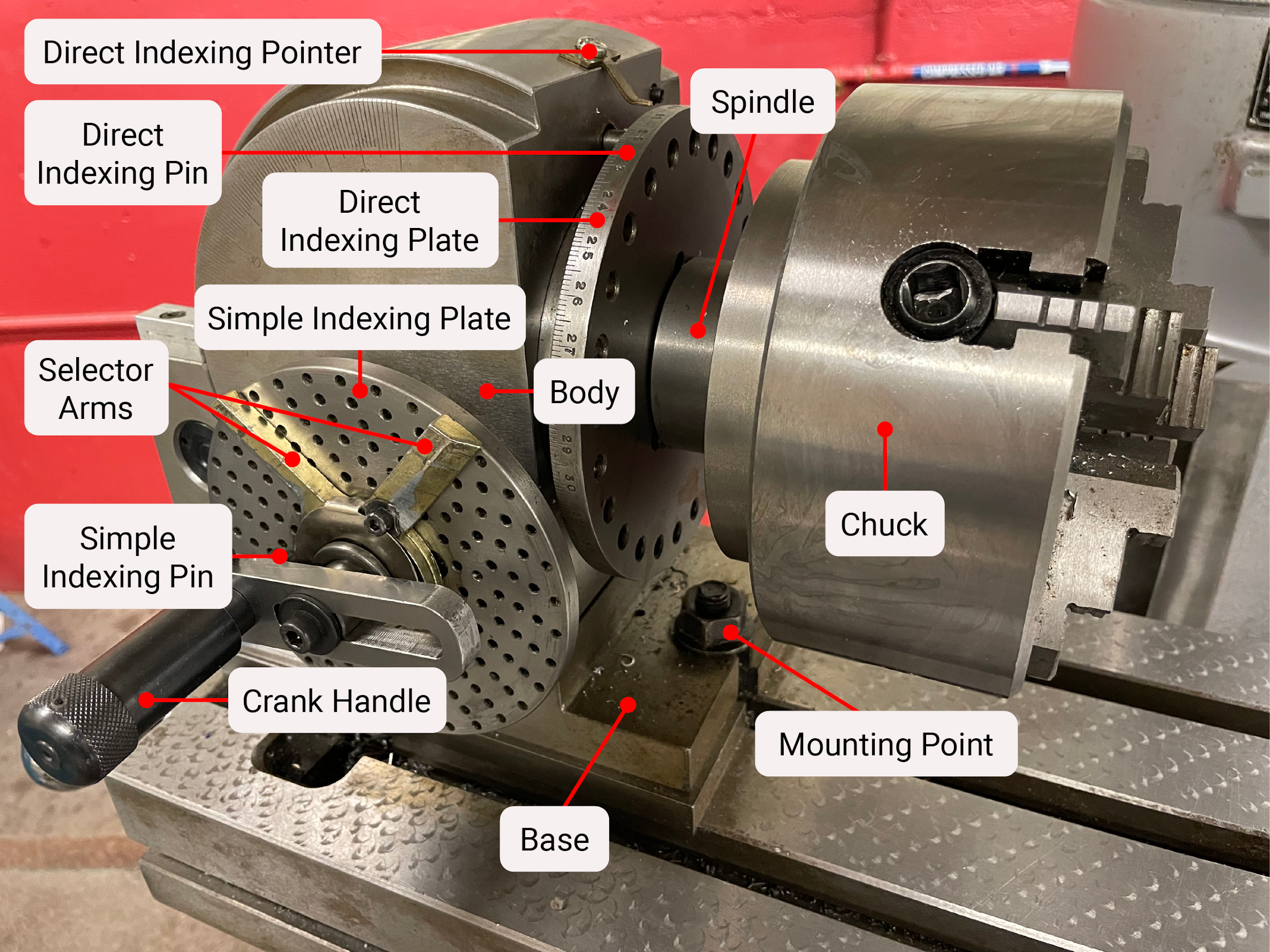
Indexing, also known as dividing, is the process of manipulating a part to machine specific features at fractions of a rotation. On a milling machine, an indexing head is used for this purpose. The indexing head is capable of quickly and easily making accurate partial rotations. Before moving forward, a few terms should be explained.
Indexing Components
The worm gear is attached to the end of a shaft that is turned by the indexing crank. The worm gear works in conjunction with the worm wheel to adjust the indexing head turning ratio. The ratio between the two is generally 40: 1 for indexing heads.
The worm wheel is attached to the beginning of a shaft that turns the spindle. The worm wheel works in conjunction with the worm gear to adjust the indexing head turning ratio. The ratio between the two is generally 40: 1 for indexing heads. The worm wheel rotates one tooth for each full rotation of the worm gear.
An indexing plate is an attachment that has predetermined hole patterns precisely placed to represent fractions of a rotation. Each manufacturer has different plates. For the examples that follow, a set of three plates will be used that have the following hole patterns.
Plate one: 15, 16, 17, 18, 19, 20.
Plate two: 21, 23, 27, 29, 31, 33.
Plate three: 37, 39, 41, 43, 47, 49.
The indexing shaft has the indexing crank attached at one end and the worm gear on the other.
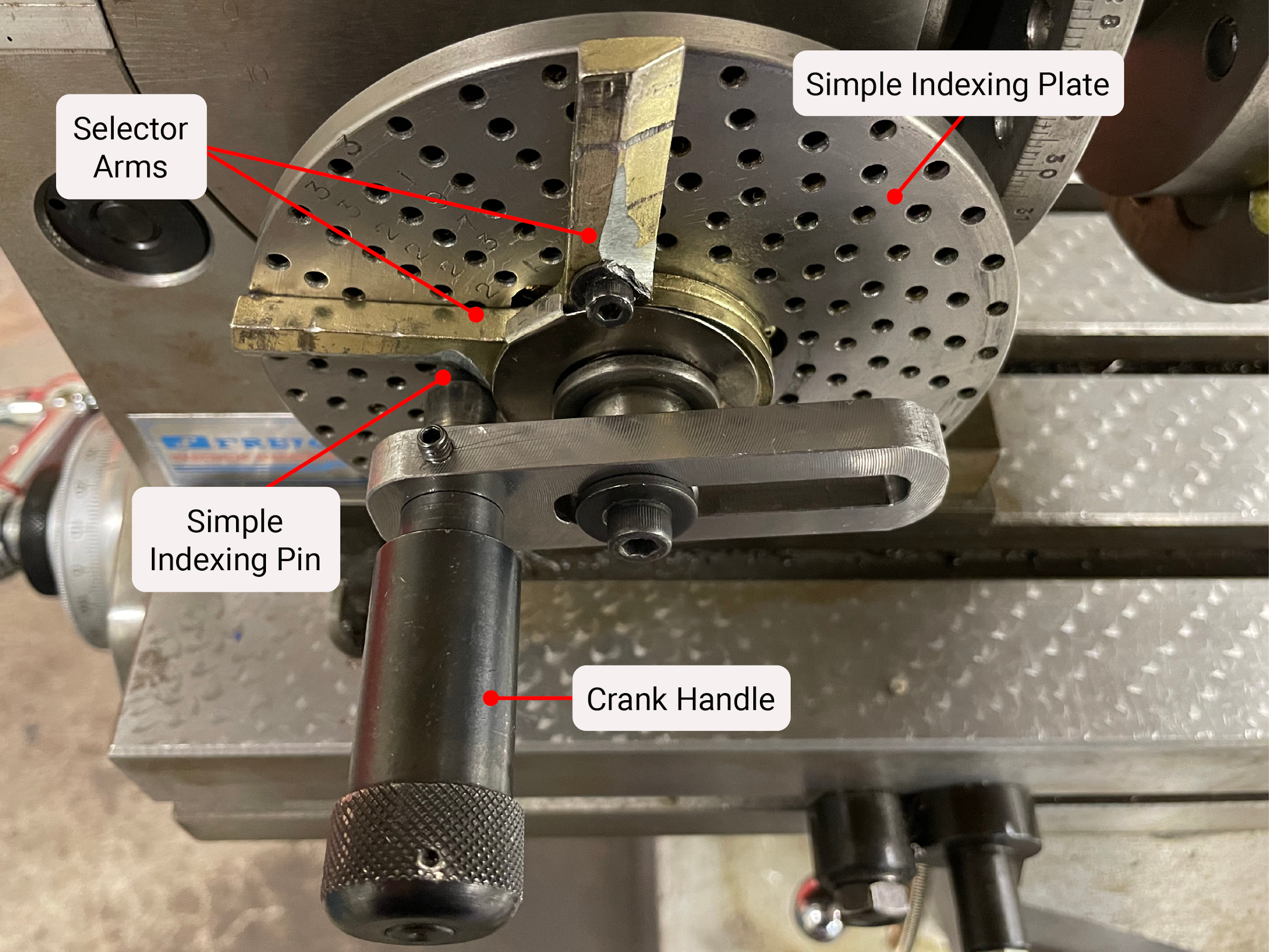
The indexing crank is used to turn the shaft that has the worm gear on it. It has a slot down the middle to make it adjustable, so that during use, it can reach multiple different hole patterns on the indexing plates.
The indexing pin is attached to the indexing crank. Once the crank is turned, the pin is placed in a hole on the indexing plate to set the position.
The selector arms are loosely attached to the shaft below the indexing crank. They are held in place by gentle friction and are intended to be moved throughout the indexing process. One arm serves to indicate the position where the pin is currently in a hole, while the other arm serves as an indicator of the hole the pin should go into on the next index. The selector arms aid in the speed and accuracy of indexing.
The spindle of the indexing head has the worm wheel attached at one end and a device to locate or attach work on the other. This may be in the form of a center, a taper, or a thread. A chuck may also be attached to the working end of the spindle.
The spindle lock is used to lock the spindle in place once the indexing has been completed. Locking the spindle allows for a more rigid machining process and protects the precise components of the indexing head.
A disengagement lever gives indexing heads the ability to disengage the connection between the indexing shaft and the spindle. This feature is helpful when utilizing direct indexing features.
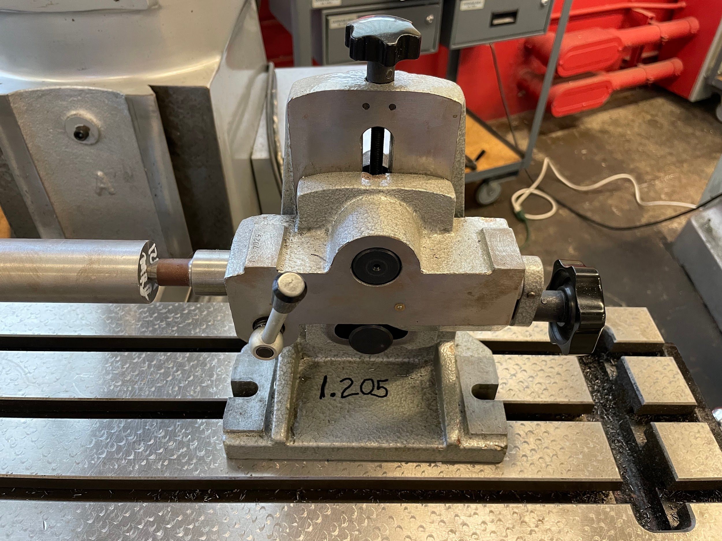
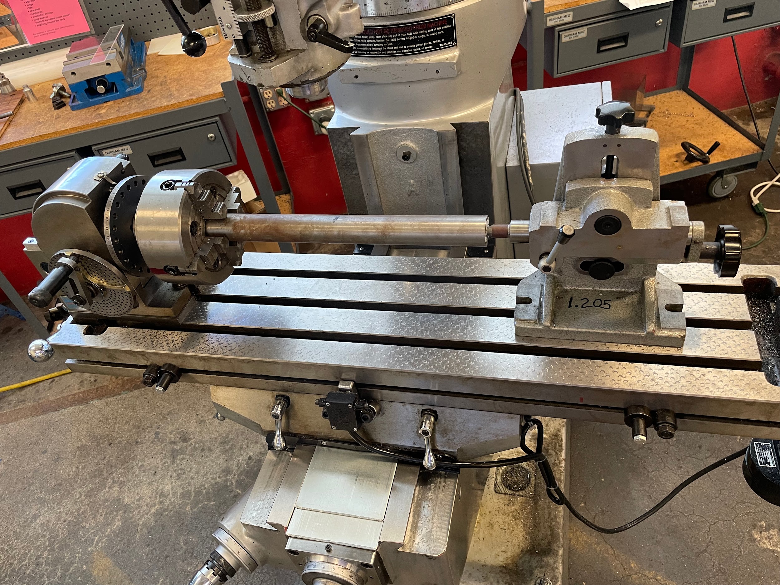
The foot stock is set opposite to the dividing head and is used to support long parts. The footstock is similar in operation to that of the tailstock on a lathe.
Direct Indexing

Direct indexing is a version of indexing that can be used to perform basic or routine divisions without the use of indexing plates. Direct indexing uses a movable pin or gear tooth mounted on the head, and a hole or mating gear on the spindle. The increment of division of direct indexing is generally 15 degrees. This will allow for some of the general indexing needs, such as a square, a hexagon, or an octagon. To decide if direct indexing is appropriate for a part, examine the situation by asking if the number of divisions reflects an angular division that is divisible equally by 15 degrees.
Number of divisions, example
For example, if a job requires 6 equal divisions of a full rotation, take the full rotational degrees and divide by 6. Now divide that number by 15 degrees. Is that a whole number?
360 / 6 = 60
60 / 15 = 4
4 is a whole number, so direct indexing is possible.
Angle of division example
Another example is using degrees instead of numbers of divisions. Two holes need to be indexed 140 degrees apart. In this example, the step of figuring out the angle based on full rotation divided by the number of divisions can be bypassed. Just divide the required angle by the 15-degree increment of the direct indexing system and see if the result is a whole number.
140 / 15 = 9.333
9.333 is not a whole number, so direct indexing is not possible.
Step by step process for direct indexing of a hex:
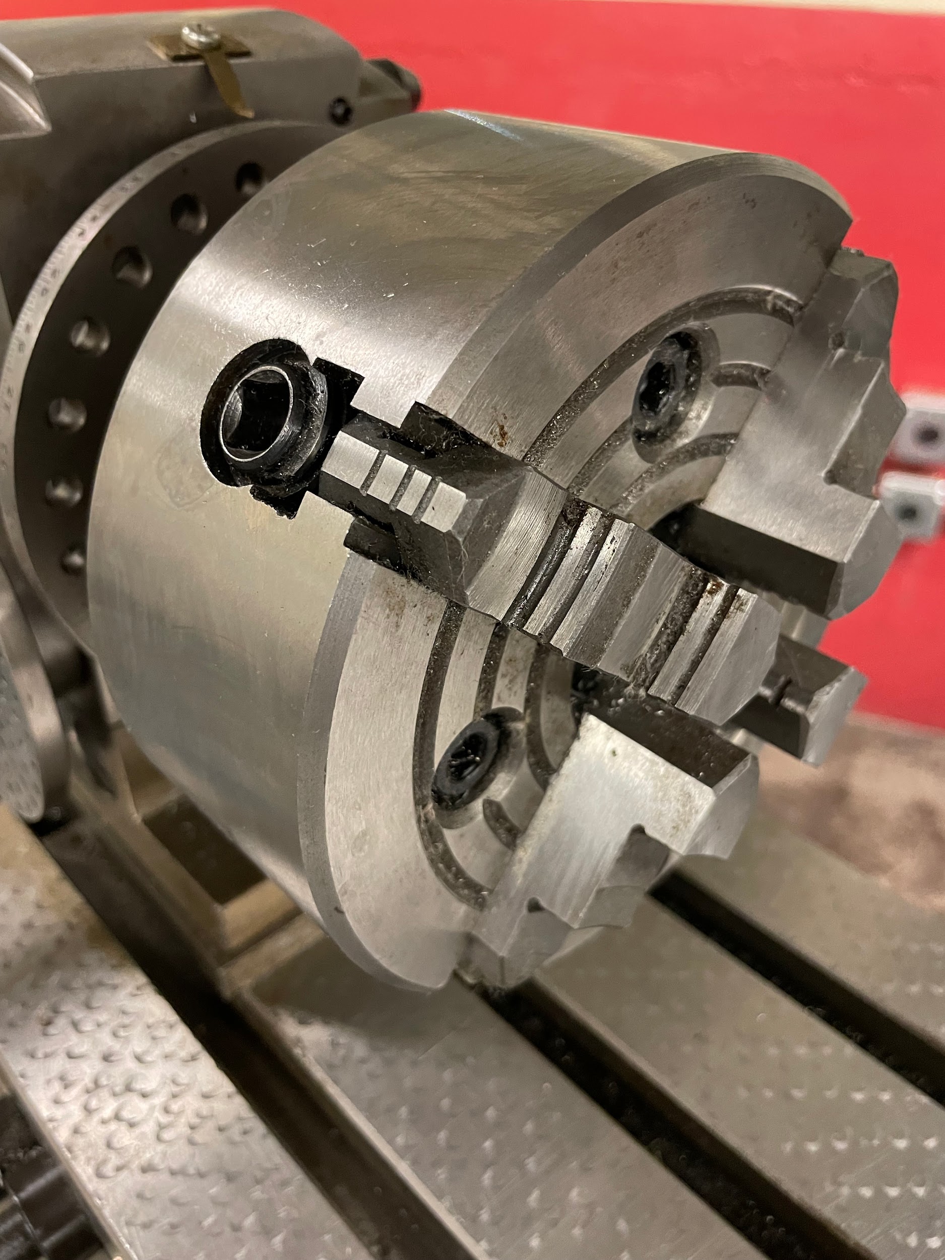
- Load a part into the four-jaw chuck of an indexing head.
- Dial in the part so it is centered.
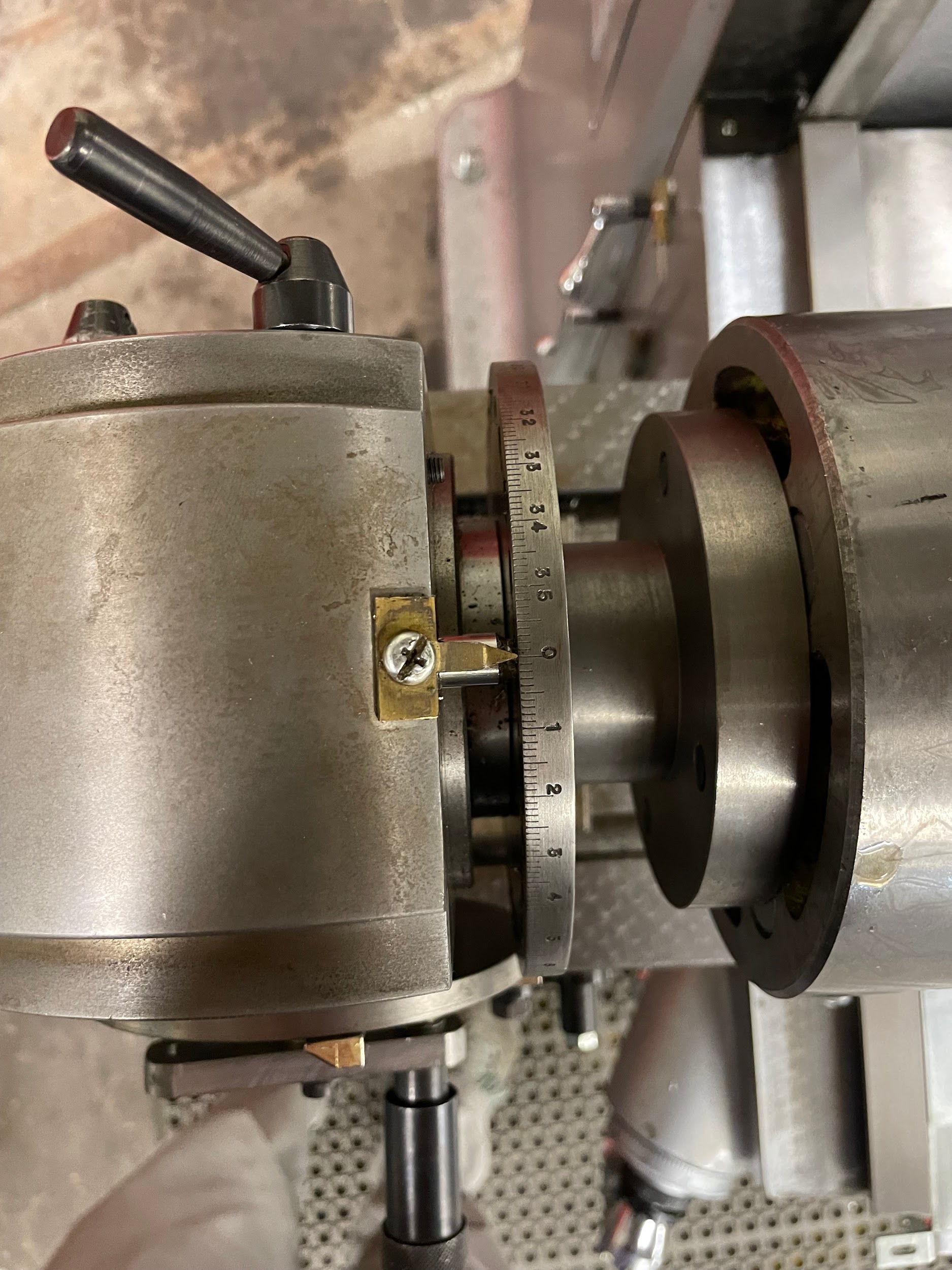
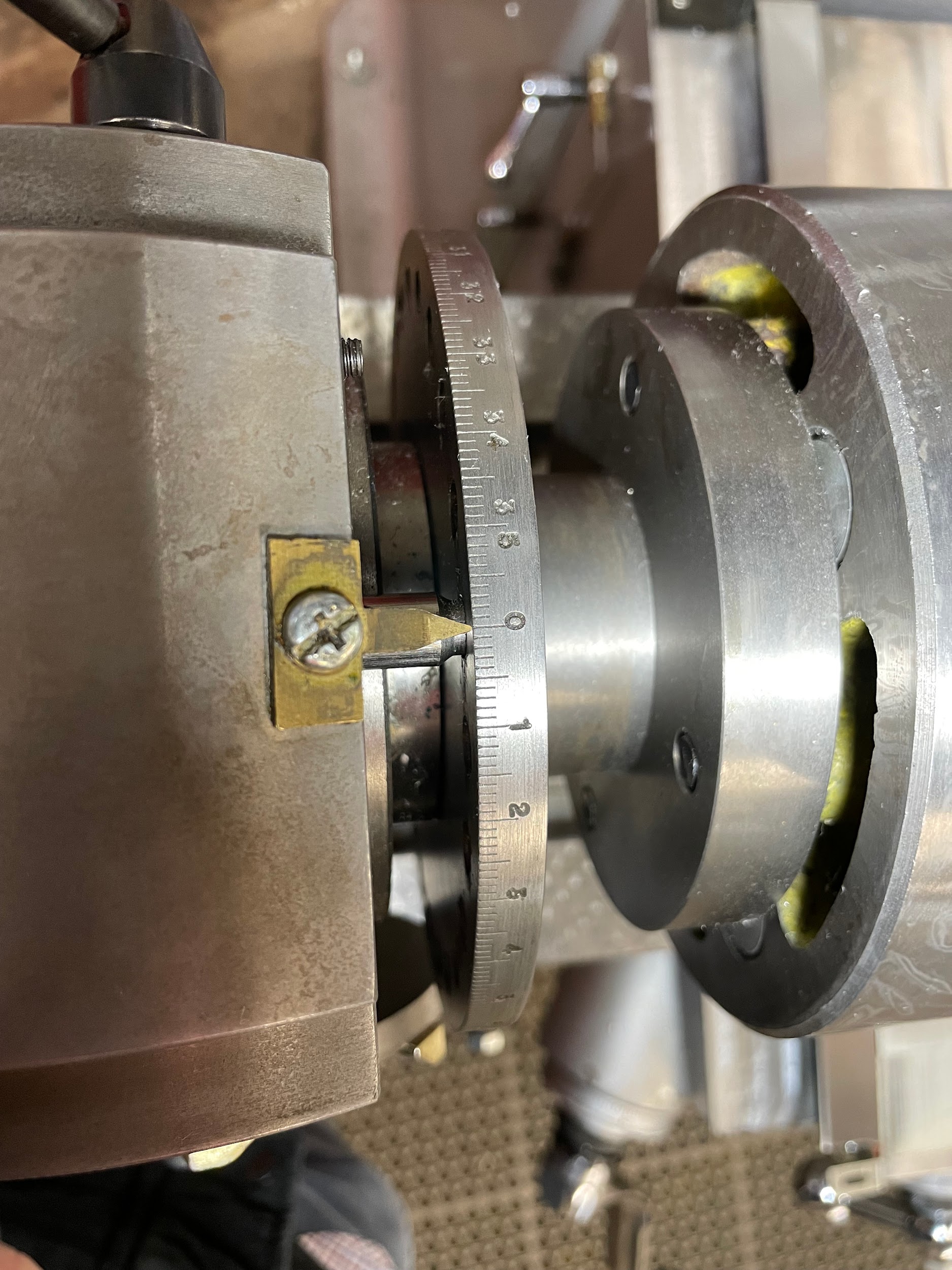
- Unlock the indexing head and rotate the spindle so the direct indexing pin sits securely in the zero position.
- Lock the indexing head.
- Lock the quill.
- Load a milling cutter. Select a milling cutter wide enough to cut the flat in one pass if possible.
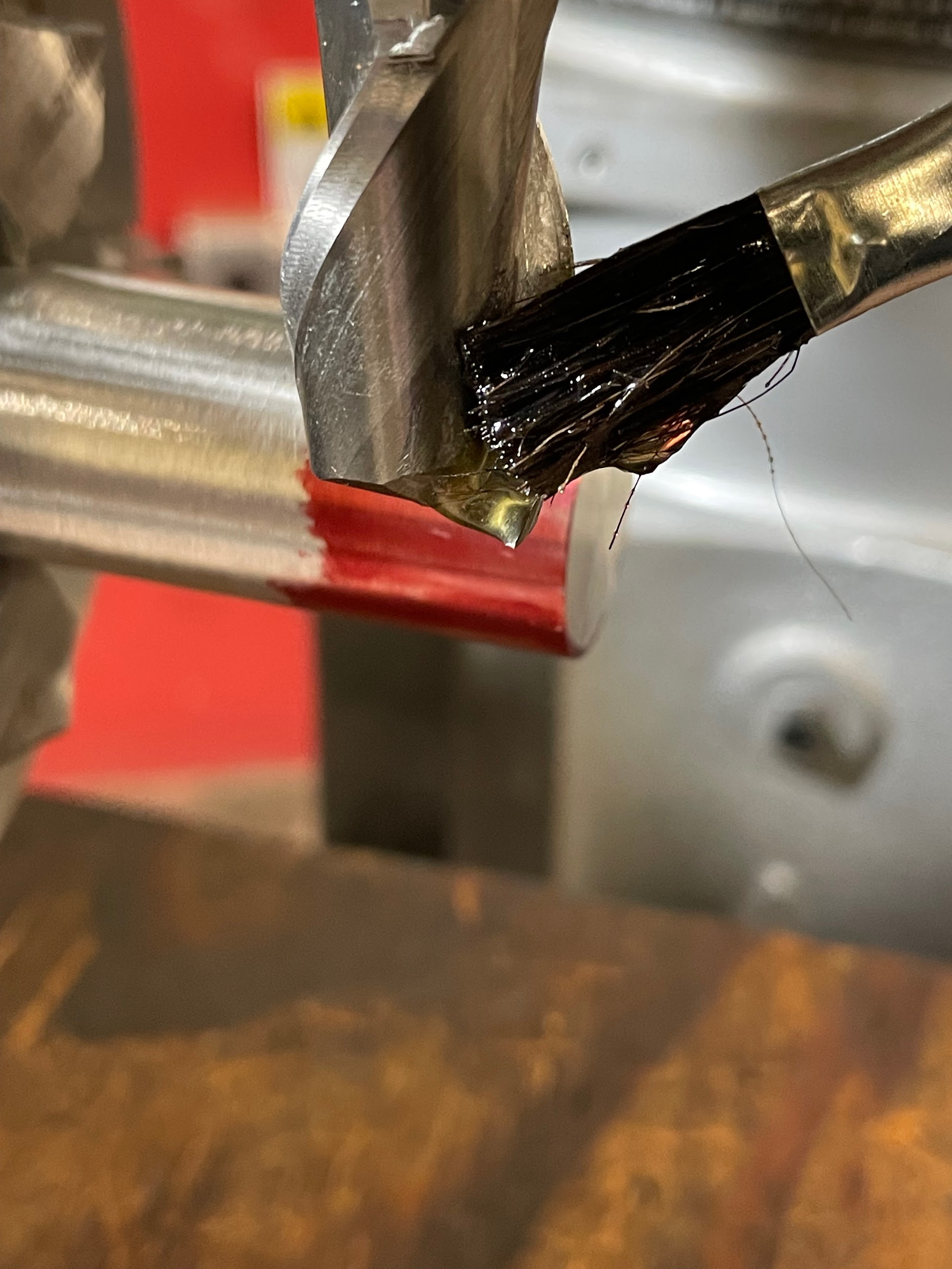
- Lube the tool.
- Turn the spindle on and set the appropriate spindle speed.
- Bring the knee up to gently touch off the outside diameter of the material.
- Zero the knee.
- Move the table over and the knee up so that the side of the tool can be touched off. Only come up enough so that the area that is touched off does not create a divot in the finished part.
- Move the table to touch-off the tool to the face of the part.
- Zero the table.
- Maneuver the cutter to the side of the work so that a conventional cut can be taken by the saddle movement.
- Move the table to the amount required, minus .010″.
- Lock the table.
- Calculate and adjust the knee to the amount required, minus .010″. Be careful; every .001″ adjustment of the knee will take .002″ off over the flats once the part has been cut all the way around.
- Cut across the part with the saddle movement.
- Bring the part back to the starting point.
- Unlock the indexing head, remove the direct indexing pin, move the spindle 60 degrees, and relock the spindle.
- Repeat the previous steps until the part has been roughed.
- Turn off the spindle and let it come to a complete stop.
- Accurately measure the depth from the end of the part to the length of the step.
- Accurately measure across the flats of the hex.
- Start the spindle and move the cutter to the side of the part where climb milling cuts would start.
- Unlock the table.
- Adjust the table to take the remaining amount of material.
- Lock the table.
- Unlock the knee.
- Adjust the knee to take in the remaining amount of material. Be careful; every .001″ adjustment of the knee will take .002″ off over the flats once the part has been cut all the way around.
- Lock the knee.
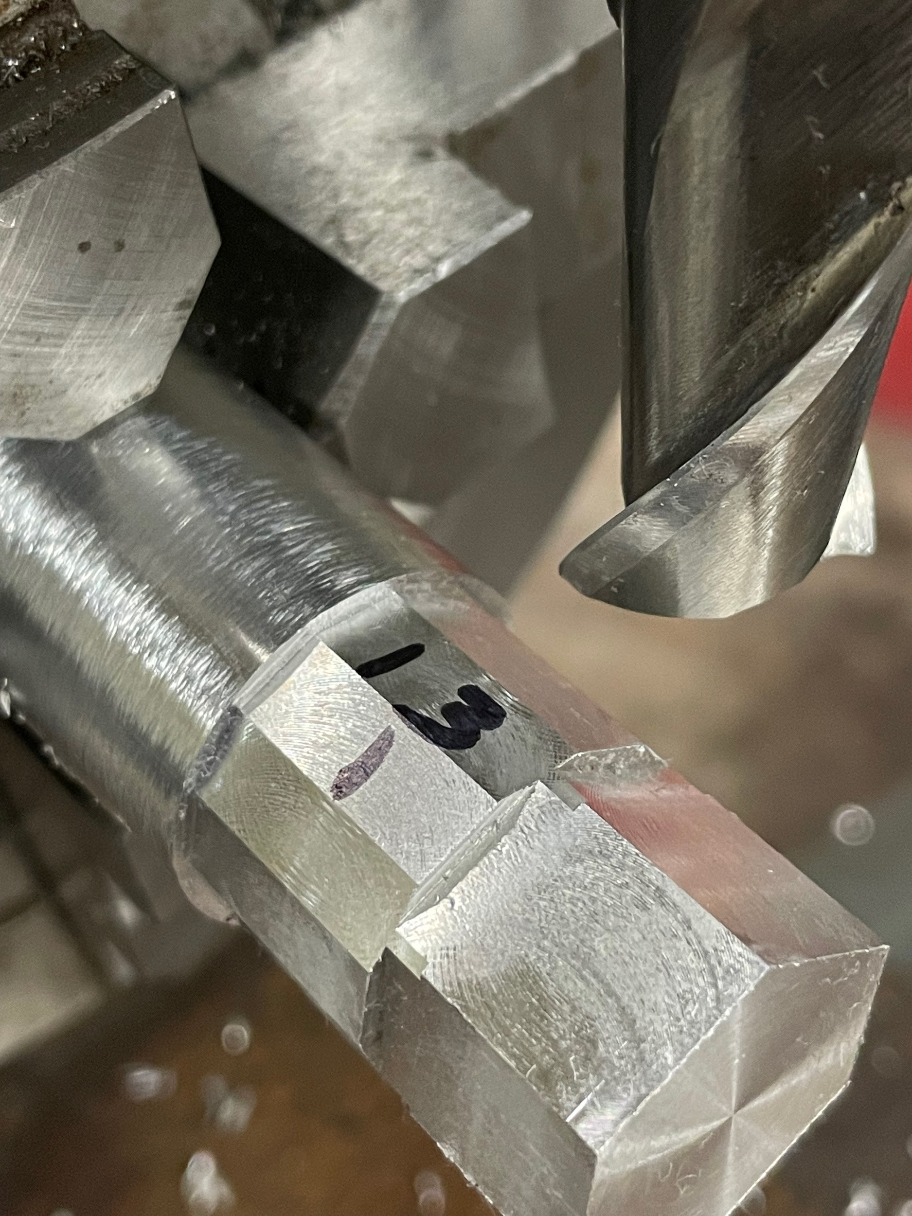
- Make the finishing cuts across the part climb milling while direct indexing as before.
Step 2: Dial in the part so it is centered.
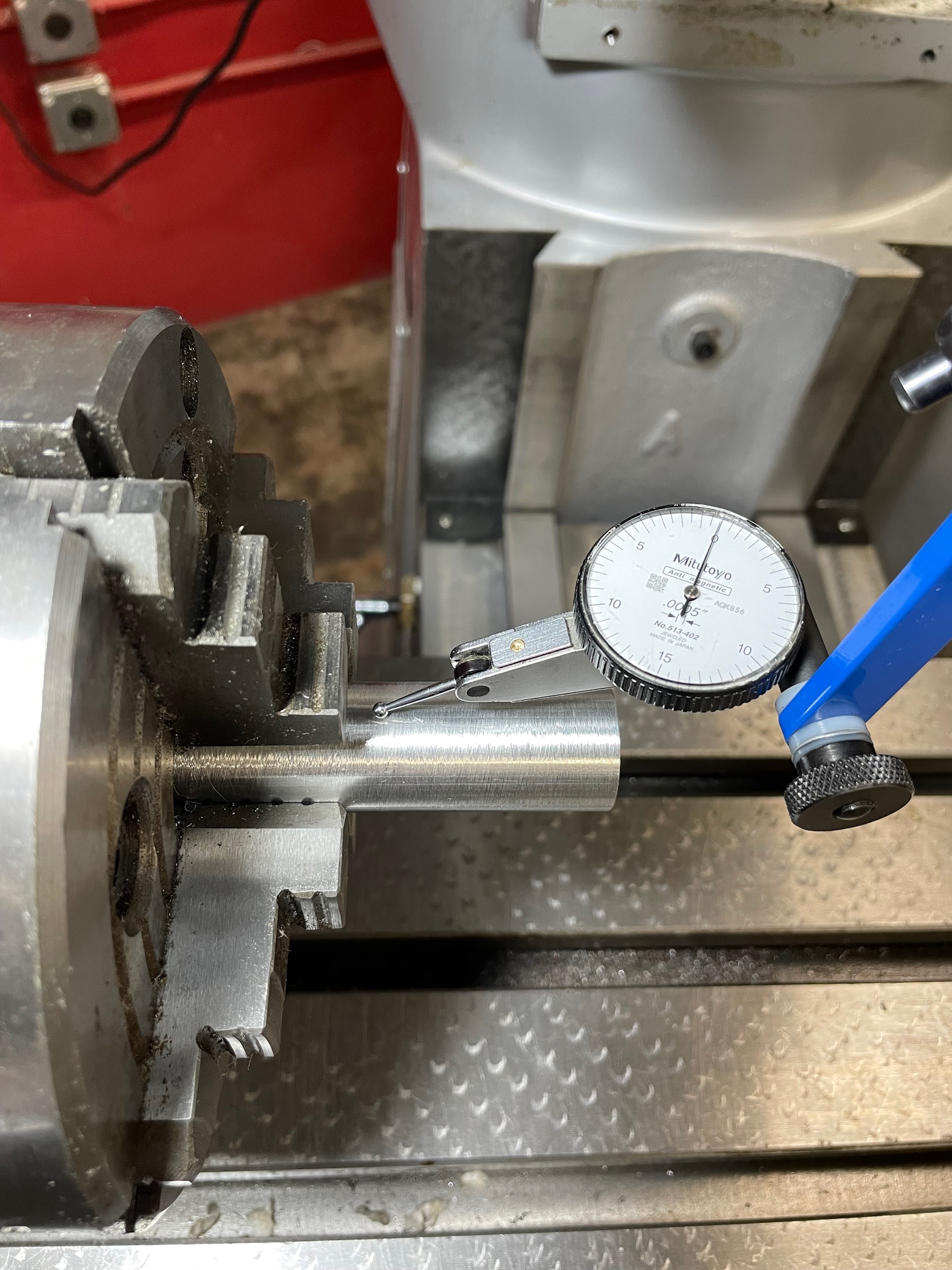
Step 2: Dial in the part so it is centered.

Step 2: Dial in the part so it is centered.

Step 3: Unlock the indexing head and rotate the spindle so the direct indexing pin sits securely in the zero position.

Step 3: Unlock the indexing head and rotate the spindle so the direct indexing pin sits securely in the zero position.

Step 7: Lube the tool.
Step 9: Bring the knee up to gently touch off the outside diameter of the material.

Step 18-19: Cut across the part with the saddle movement. Bring the part back to the starting point.

Step 20: Unlock the indexing head, remove the direct indexing pin, move the spindle 60 degrees, and relock the spindle.

Step 20: Unlock the indexing head, remove the direct indexing pin, move the spindle 60 degrees, and relock the spindle.

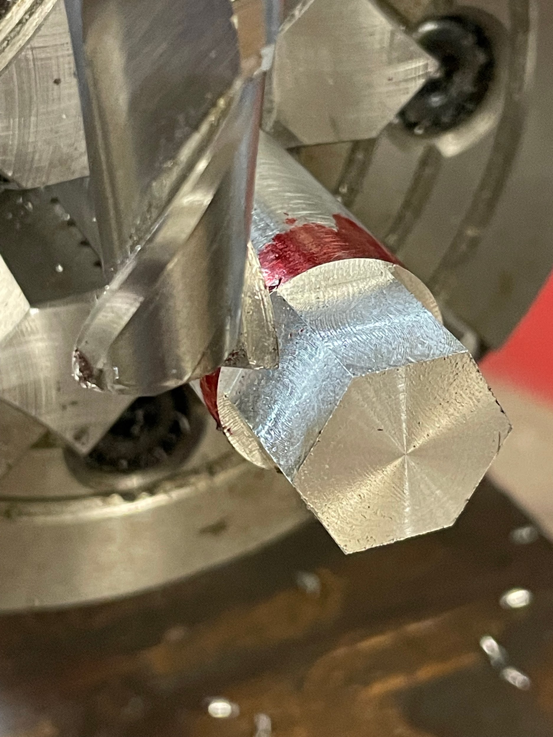
Step 21: Repeat the previous steps until the part has been roughed.

Step 32: Make the finishing cuts across the part climb milling while direct indexing as before.
Simple Indexing
Simple indexing is used to create divisions around a circle that are not possible by direct indexing. Simple indexing utilizes the indexing plates, crank, and pin to accurately position the spindel.
Example
A part requires 13 equal divisions around the outside of a part. First, it should be checked for the ability of direct indexing.
360 / 13 = 27.692
27.692 / 15 = 1.846
1.846 is not a whole number, so direct indexing is not possible.
Once this is determined, the number of divisions can be input into the formula to calculate simple indexing. The formula is:
40 / N = Indexing
40 represents the ratio of turns of the indexing crank to the revolutions of the spindle. This may be different depending on the brand of indexing head. “N” is the number of divisions required. The key to finding the solution is by keeping the indexing answer in fraction form. Basically, pulling out the whole numbers from a potentially improper fraction.
40 / 13 = 3 and 1/13
Reduce the fraction if possible. In this case, 1/13 can not be reduced any further.
After that process, the fraction is ready to be applied to the indexing plate. Examine the three plates from the previous definition and look for the hole pattern that matches the denominator of the fraction.
13 isn’t on any of the plates.
An equivalent fraction must be found for 1/13 that will apply to the plates. The easiest way to accomplish this is to take the denominator of the fraction, multiply it by two, and check the plates for a match. If it doesn’t match, multiply the denominator by three and check again. Continue this process until a match is found.
13 × 2 = 26
26 isn’t a pattern on any of the plates.
13 × 3 = 39
39 matches a hole pattern on plate three.
Once the hole pattern has been selected, the fraction is converted to one that can be demonstrated on the plate. To do this, multiply the numerator by the same value the denominator was multiplied by when the correct hole pattern was matched. This will give the number of holes needed to advance the indexing crank once the full turns have been completed.
The number the denominator was multiplied by was 3 to find a match for the 39-hole pattern. To keep the fraction equal, the numerator and denominator need to be multiplied by the same number. It is basically an expansion of the fraction.
1 / 13 = ? / 39
1 / 13 = 3 / 39
With the fraction converted to a form that is demonstrable on an indexing plate, the final rotations of the indexing handwheel for each division can be expressed.
1 index = 3 full rotations of the crank and 3 holes on a 39-hole pattern.
Step by step process simple indexing a 13-sided part:
- Load a part into the four-jaw chuck of an indexing head.
- Dial in the part so it is centered.
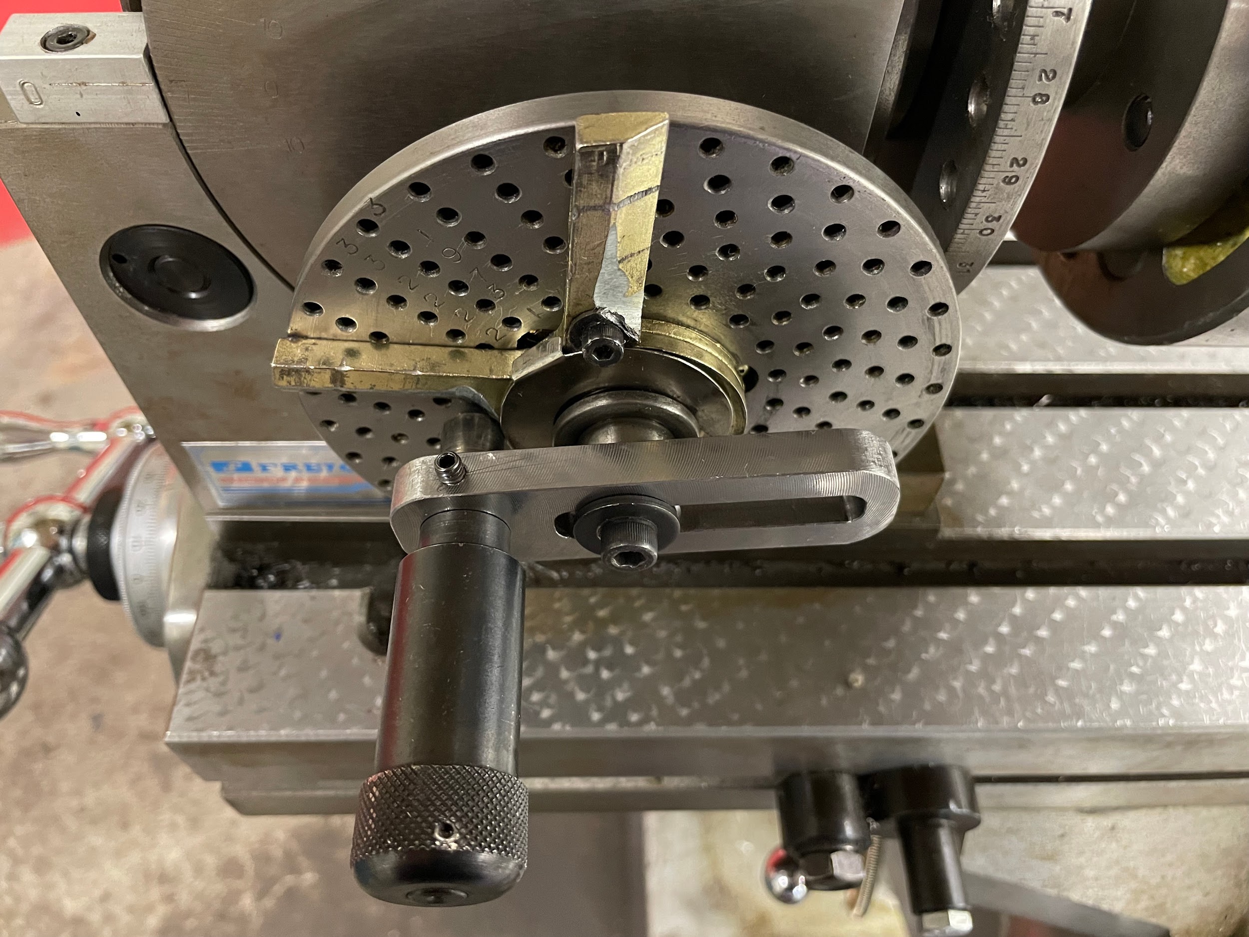
- Adjust the indexing crank so the indexing pin will align with the correct hole pattern in the indexing plate. In this example, it is the 39-bolt hole pattern.
- Unlock the indexing head and rotate the spindle using the indexing crank and indexing pin. Place the pin into a hole in the indexing plate to establish a starting position for simple indexing. Take care to only move the crank in one direction to eliminate backlash error.
- Lock the indexing head.
- Set and lock the selector arms. In this example, there will be 3 holes from the first position.
- Lock the quill.
- Load a milling cutter. Select a milling cutter wide enough to cut the flat in one pass, if possible.
- Lube the tool.
- Turn the spindle on and set the appropriate spindle speed.
- Bring the tool down and gently touch off the outside diameter of the material.
- Zero the knee.
- Move the table over and the knee up so that the side of the tool can be touched off. Only come up enough so that the area that is touched off does not create a divot in the finished part.
- Move the table to touch-off the tool to the face of the part.
- Zero the table.
- Maneuver the cutter to the side of the work so that a conventional cut can be taken by the saddle movement.
- Move the table to the amount required, minus .010″.
- Lock the table.
- Calculate and adjust the knee to the amount required, minus .010″. Be careful; every .001″ adjustment of the knee will take .002″ off over the flats once the part has been cut all the way around.
- Cut across the part with the saddle movement.
- Bring the part back to the starting point.
- Unlock the indexing head, adjust the selector arms, remove the indexing pin, move the indexing crank (3 turns and 3 holes in this example), and relock the spindle.
- Repeat the previous steps until the part has been roughed.
- Turn off the spindle and let it come to a complete stop.
- Accurately measure the depth from the end of the part to the length of the step.
- Accurately measure the depth of the flats.
- Start the spindle and move the cutter to the side of the part where climb milling cuts would start.
- Unlock the table.
- Adjust the table to take the remaining amount of material.
- Lock the table.
- Unlock the knee.
- Adjust the knee to take in the remaining amount of material. Be careful; every .001″ adjustment of the knee will take .002″ off over the flats once the part has been cut all the way around.
- Lock the knee.
- Make the finishing cuts across the part climb milling, and simple indexing as before.
Step 3: Adjust the indexing crank so the indexing pin will align with the correct hole pattern in the indexing plate. In this example, it is the 39-bolt hole pattern.

Step 6: Set and lock the selector arms. In this example, there will be 3 holes from the first position.

Step 20-21: Cut across the part with the saddle movement. Bring the part back to the starting point.

Step 22: Unlock the indexing head, adjust the selector arms, remove the indexing pin, move the indexing crank (3 turns and 3 holes in this example), and relock the spindle.

Step 23: Repeat the previous steps until the part has been roughed.

Step 34: Make the finishing cuts across the part climb milling, and simple indexing as before.

Step 34: Make the finishing cuts across the part climb milling, and simple indexing as before.

Angular indexing
Angular indexing is similar to simple indexing in that the operator can use the indexing plates, crank and pin to set the indexed position, but it is different in that the formula is based on the fact that one revolution of the indexing crank is equal to 9 degrees when a 40 : 1 ratio is used.
1 rotation of the crank = 1/40th of the spindle
1/40 of 360 degrees in a circle = The degrees in 1 rotation of the crank
(1 / 40) × 360 = 9-degrees
Example
If the previous example is looked at, where direct indexing couldn’t be used to machine two holes that needed to be indexed 140 degrees apart, angular indexing can now be employed. Knowing that the base for the math is the 9-degree of rotation of the crank, the number of degrees needed should be divided by 9 to come up with the number of rotations of the crank. Remember to keep the number of rotations as a fraction.
Degrees of index / 9 = crank rotations
140 / 9 = 15 and 3 / 9
Or
15 and 1 / 3 once reduced
Now that this calculation has been made, the fraction is ready to be applied to the indexing plate. Examine the three plates from the previous definition and look for the hole pattern that matches the denominator of the fraction.
3 isn’t on any of the plates.
An equivalent fraction must be found for 1/3 that will apply to the plates. The easiest way to accomplish this is to take the denominator of the fraction, multiply it by two, and check the plates for a match. If it doesn’t match, multiply the denominator by three and check again. Continue this process until a match is found.
3 × 2 = 6
6 isn’t on any of the plates.
3 × 3 = 9
9 isn’t on any of the plates.
3 × 4 = 12
12 isn’t on any of the plates.
3 × 5 = 15
15 matches a hole pattern on plate one.
Once the hole pattern has been selected, the fraction is converted to one that can be demonstrated on the plate. To do this, multiply the numerator by the same value the denominator was multiplied by when the correct hole pattern was matched. This will give the number of holes needed to advance the indexing crank once the full turns have been completed.
The number the denominator was multiplied by was 5 to find a match for the 39-hole pattern. To keep the fraction equal, the numerator and denominator need to be multiplied by the same number. It is basically an expansion of the fraction.
1 / 3 = ? / 15
1 / 3 = 5 / 15
With the fraction converted to a form that is demonstrable on an indexing plate, the final rotations of the indexing handwheel for the indexing between the two holes can be expressed.
Indexing = 15 full rotations of the crank and 5 holes on a 15-hole pattern.
Attributions
- Figure 9.235: A part with indexed sides by Micky R. Jennings, courtesy of Wenatchee Valley College, for WA Open ProfTech, © SBCTC, CC BY 4.0
- Figure 9.236: Indexing head by Micky R. Jennings, courtesy of Wenatchee Valley College, for WA Open ProfTech, © SBCTC, CC BY 4.0
- Figure 9.237: Indexing head 2 by Micky R. Jennings, courtesy of Wenatchee Valley College, for WA Open ProfTech, © SBCTC, CC BY 4.0
- Figure 9.238: Indexing head 3 by Micky R. Jennings, courtesy of Wenatchee Valley College, for WA Open ProfTech, © SBCTC, CC BY 4.0
- Figure 9.239: Indexing head 4 by Micky R. Jennings, courtesy of Wenatchee Valley College, for WA Open ProfTech, © SBCTC, CC BY 4.0
- Figure 9.240: Foot stock by Micky R. Jennings, courtesy of Wenatchee Valley College, for WA Open ProfTech, © SBCTC, CC BY 4.0
- Figure 9.241: Indexing head and foot stock by Micky R. Jennings, courtesy of Wenatchee Valley College, for WA Open ProfTech, © SBCTC, CC BY 4.0
- Figure 9.242: Direct indexing by Micky R. Jennings, courtesy of Wenatchee Valley College, for WA Open ProfTech, © SBCTC, CC BY 4.0
- Video 9.87: Micky R. Jennings, courtesy of Wenatchee Valley College, for WA Open ProfTech, © SBCTC, CC BY 4.0
- Figure 9.243: Center part by Micky R. Jennings, courtesy of Wenatchee Valley College, for WA Open ProfTech, © SBCTC, CC BY 4.0
- Video 9.88: Micky R. Jennings, courtesy of Wenatchee Valley College, for WA Open ProfTech, © SBCTC, CC BY 4.0
- Video 9.89: Micky R. Jennings, courtesy of Wenatchee Valley College, for WA Open ProfTech, © SBCTC, CC BY 4.0
- Figure 9.244: Direct indexing zero by Micky R. Jennings, courtesy of Wenatchee Valley College, for WA Open ProfTech, © SBCTC, CC BY 4.0
- Video 9.90: Micky R. Jennings, courtesy of Wenatchee Valley College, for WA Open ProfTech, © SBCTC, CC BY 4.0
- Figure 9.245: Oil endmill by Micky R. Jennings, courtesy of Wenatchee Valley College, for WA Open ProfTech, © SBCTC, CC BY 4.0
- Video 9.91: Micky R. Jennings, courtesy of Wenatchee Valley College, for WA Open ProfTech, © SBCTC, CC BY 4.0
- Video 9.92: Micky R. Jennings, courtesy of Wenatchee Valley College, for WA Open ProfTech, © SBCTC, CC BY 4.0
- Video 9.93: Micky R. Jennings, courtesy of Wenatchee Valley College, for WA Open ProfTech, © SBCTC, CC BY 4.0
- Video 9.94: Micky R. Jennings, courtesy of Wenatchee Valley College, for WA Open ProfTech, © SBCTC, CC BY 4.0
- Video 9.95: Micky R. Jennings, courtesy of Wenatchee Valley College, for WA Open ProfTech, © SBCTC, CC BY 4.0
- Figure 9.246: Finished direct indexing by Micky R. Jennings, courtesy of Wenatchee Valley College, for WA Open ProfTech, © SBCTC, CC BY 4.0
- Figure 9.247: Simple indexing by Micky R. Jennings, courtesy of Wenatchee Valley College, for WA Open ProfTech, © SBCTC, CC BY 4.0
- Video 9.96: Micky R. Jennings, courtesy of Wenatchee Valley College, for WA Open ProfTech, © SBCTC, CC BY 4.0
- Video 9.97: Micky R. Jennings, courtesy of Wenatchee Valley College, for WA Open ProfTech, © SBCTC, CC BY 4.0
- Video 9.98: Micky R. Jennings, courtesy of Wenatchee Valley College, for WA Open ProfTech, © SBCTC, CC BY 4.0
- Video 9.99: Micky R. Jennings, courtesy of Wenatchee Valley College, for WA Open ProfTech, © SBCTC, CC BY 4.0
- Video 9.100: Micky R. Jennings, courtesy of Wenatchee Valley College, for WA Open ProfTech, © SBCTC, CC BY 4.0
- Figure 9.248: Simple indexing 2 by Micky R. Jennings, courtesy of Wenatchee Valley College, for WA Open ProfTech, © SBCTC, CC BY 4.0
- Video 9.101: Micky R. Jennings, courtesy of Wenatchee Valley College, for WA Open ProfTech, © SBCTC, CC BY 4.0
The process of rotating a workpiece in precise increments. See also dividing
The process of rotating a workpiece in precise increments. See also indexing
A gear that is a tight helix around a shaft, similar to an external thread.
A gear designed to mesh with a worm gear. It looks similar to a spur gear.
A plate with a set, or sets, of predetermined hole patterns used as a template for indexing.
The shaft that connects the indexing crank to the worm gear.
The lever the operator turns in order to rotate an indexing head.
The pin that is placed into the holes of the indexing plates during the positioning process.
A time savings and accuracy device used during simple indexing that eliminates the need to count the holes of the indexing plate for each division.
The powered rotational component of a machine tool.
A device that is used to secure the spindle from moving during machining operations.
A lever that allows the operator to put the indexing head into a neutral state for ease of movement.
A support component that is used when indexing long flexible workpieces.
The process of indexing that uses the larger increments of the direct indexing plate, Often in course angular increments.
The process of indexing that uses the smaller increments of the simple indexing plates. This process is based on revolving the work in fractions of a full rotation.
The process of executing simple indexing based on desired angles rather than fractions of a rotation.
