9.3 Machine Components
Micky R. Jennings
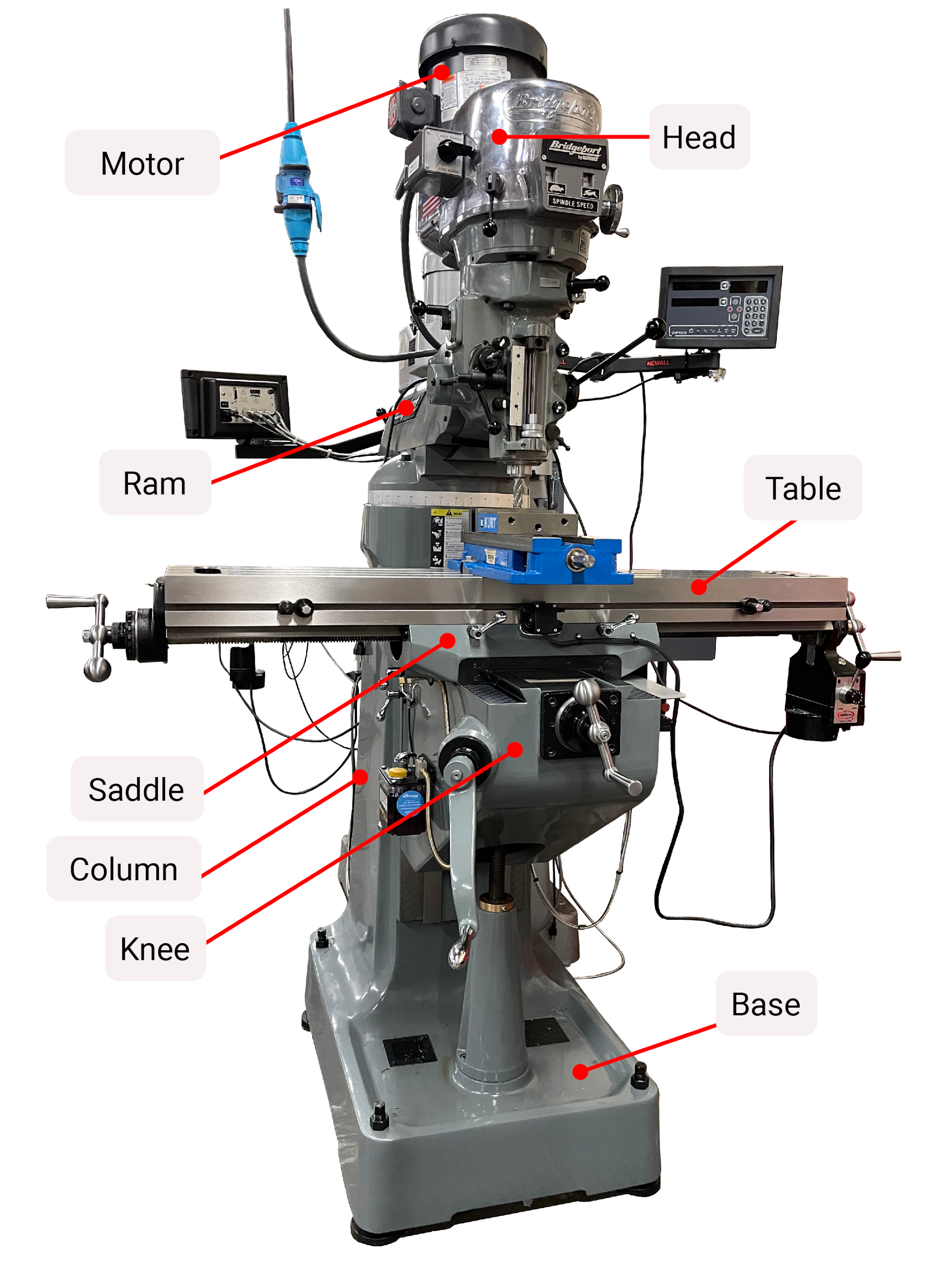
It is important that all mill operators are familiar with the components of the machinery they are using. Getting to know the equipment, features, and functionality will help the machinist perform work in the safest and most efficient manner, as well as give them the industry specific nomenclature necessary to effectively communicate with coworkers. Modern vertical manual milling machines are modeled after the popular machines that have been produced by Bridgeport Machines, Inc. since the 1930s. For that reason, milling machines are often referred to as “Bridgeports” (Jacobs, 2022). Although the design and function of most milling machines are similar, an area of difference is the size and capacity. Milling machines are usually advertised by the size of the table to which the work is mounted. A common size is 9″ X 49″, meaning that the table itself is 9″ wide and 49″ long. It is important to note that the machine’s travel and the distance the table can move, are different from the size of the machine.
Base
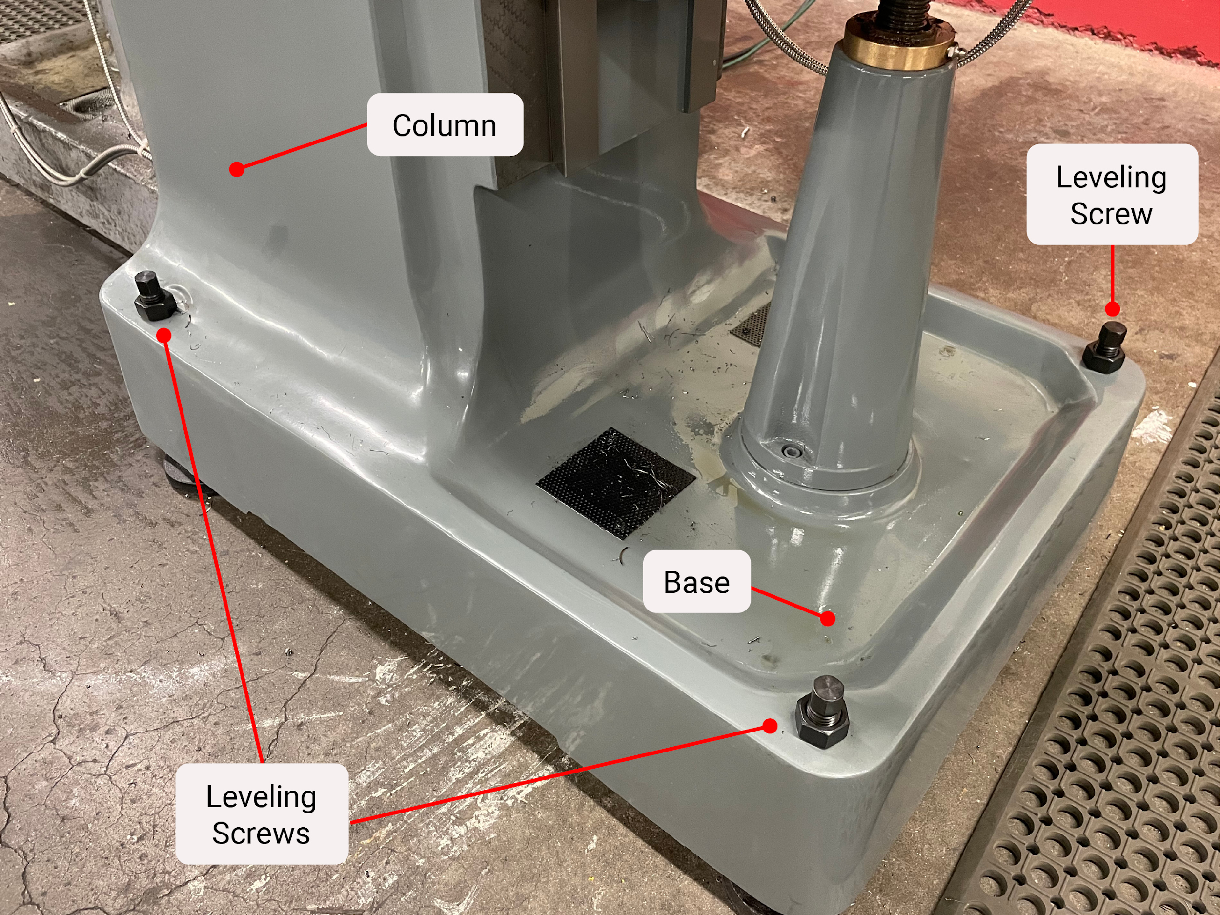
The base of a milling machine is made of heavy cast iron and provides a secure, stable platform for machining. On most machines, the column is cast as one piece with the base. Attached to the base is the screw that allows the knee to be raised and lowered. The base will have leveling screws and a way to anchor the machine to the floor. The base will often contain a reservoir for coolant or cutting oil.
Column
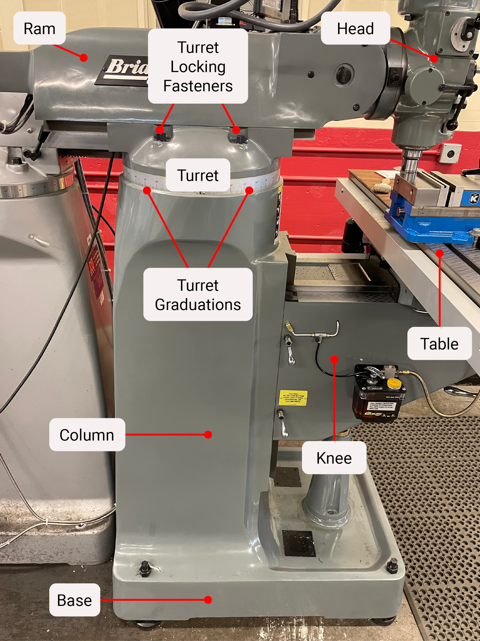
The column is cast as one piece with the base. The column is designed as a rigid support for the ram at the top of the column, often having an adjustable rotational pivot that allows the head to be moved radially. The column also gives support to the knee by means of precision ways.
Ram
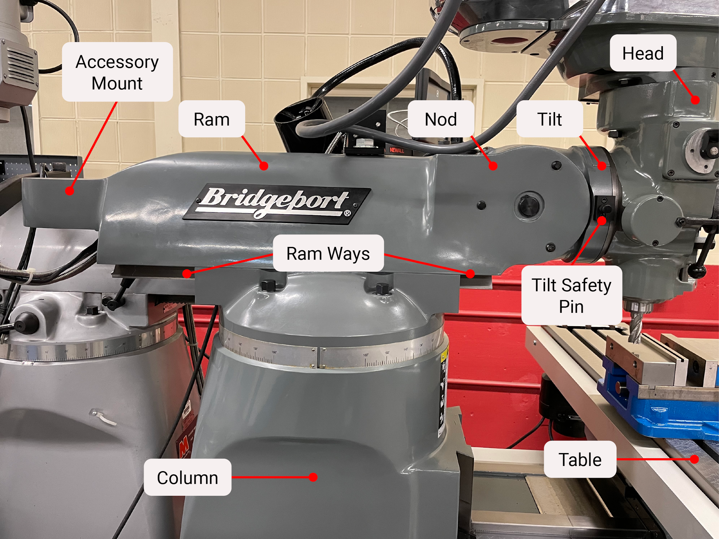
The ram sits on top of the column and is adjustable in and out on precision ways. At the end of the ram is the head. The attachment point between the head and the ram contains two pivot points. The first controls a front and back nodding rotation, and the second controls tilting side to side rotation. At the back of the ram is a mounting point for other milling machine attachments, such as rack milling or broaching.
Head
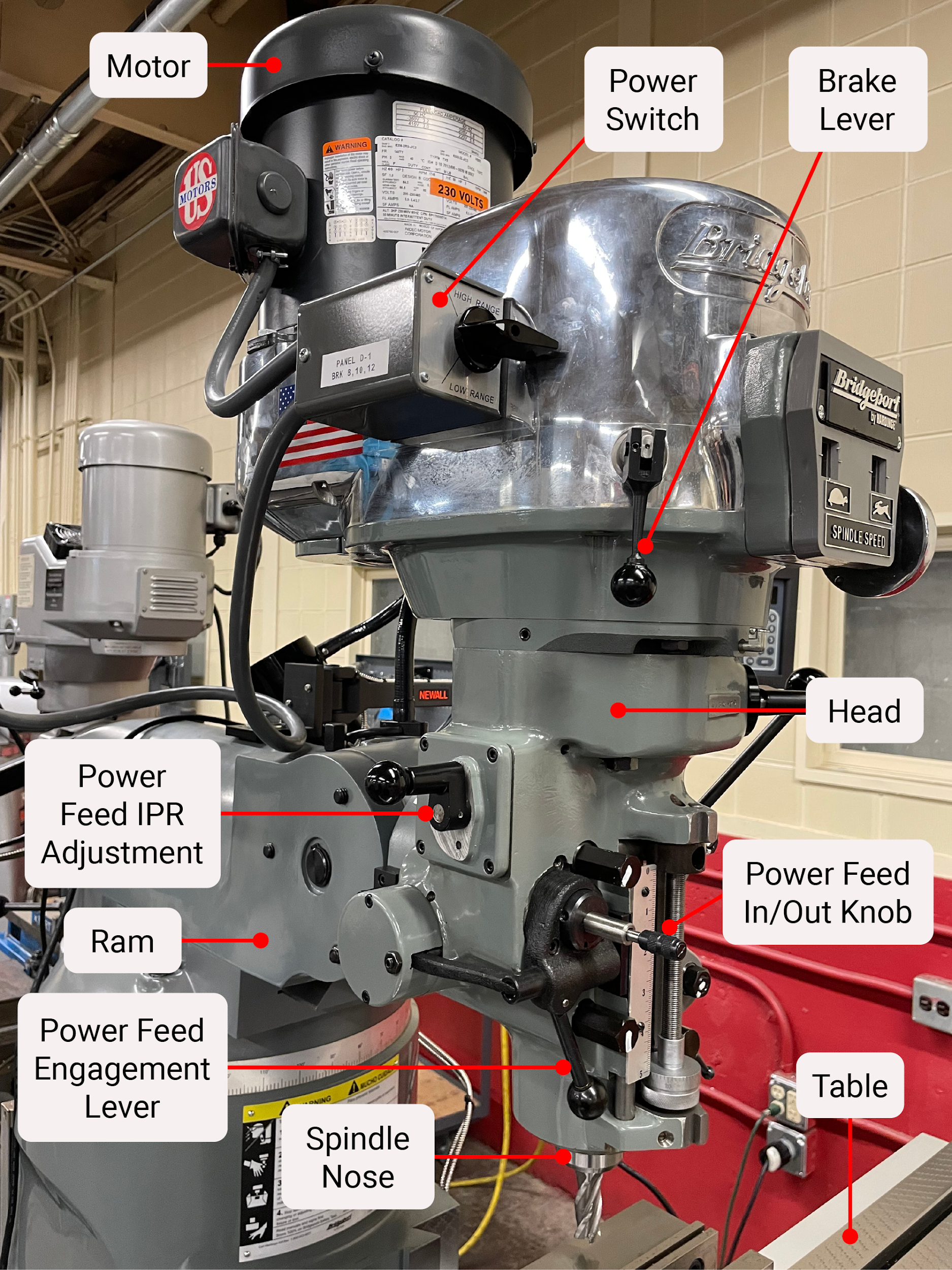
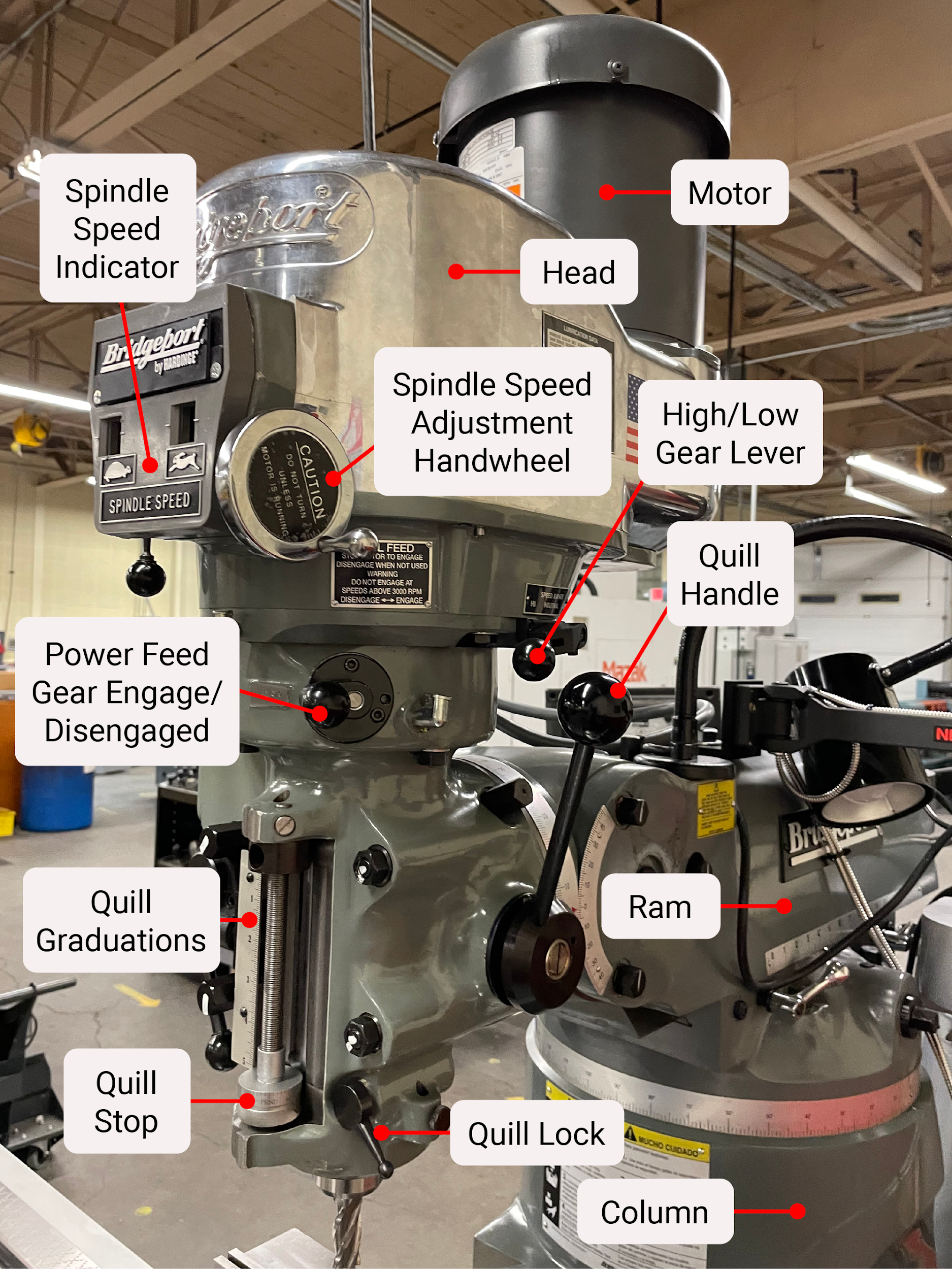
The head of the milling machine contains the motor, the spindle, the quill, the drawbar, and various other components needed to drive and feed the cutting tool. To the right of the head is the quill feed handle that the operator uses to control hole making operations in the same fashion as on the drill press. The quill moves the tool up and down along the Z axis of the three-dimensional coordinate system. The head has the ability to nod forward and backward, as well as tilt from side to side, to create angled cuts or features on angled surfaces.
Motor
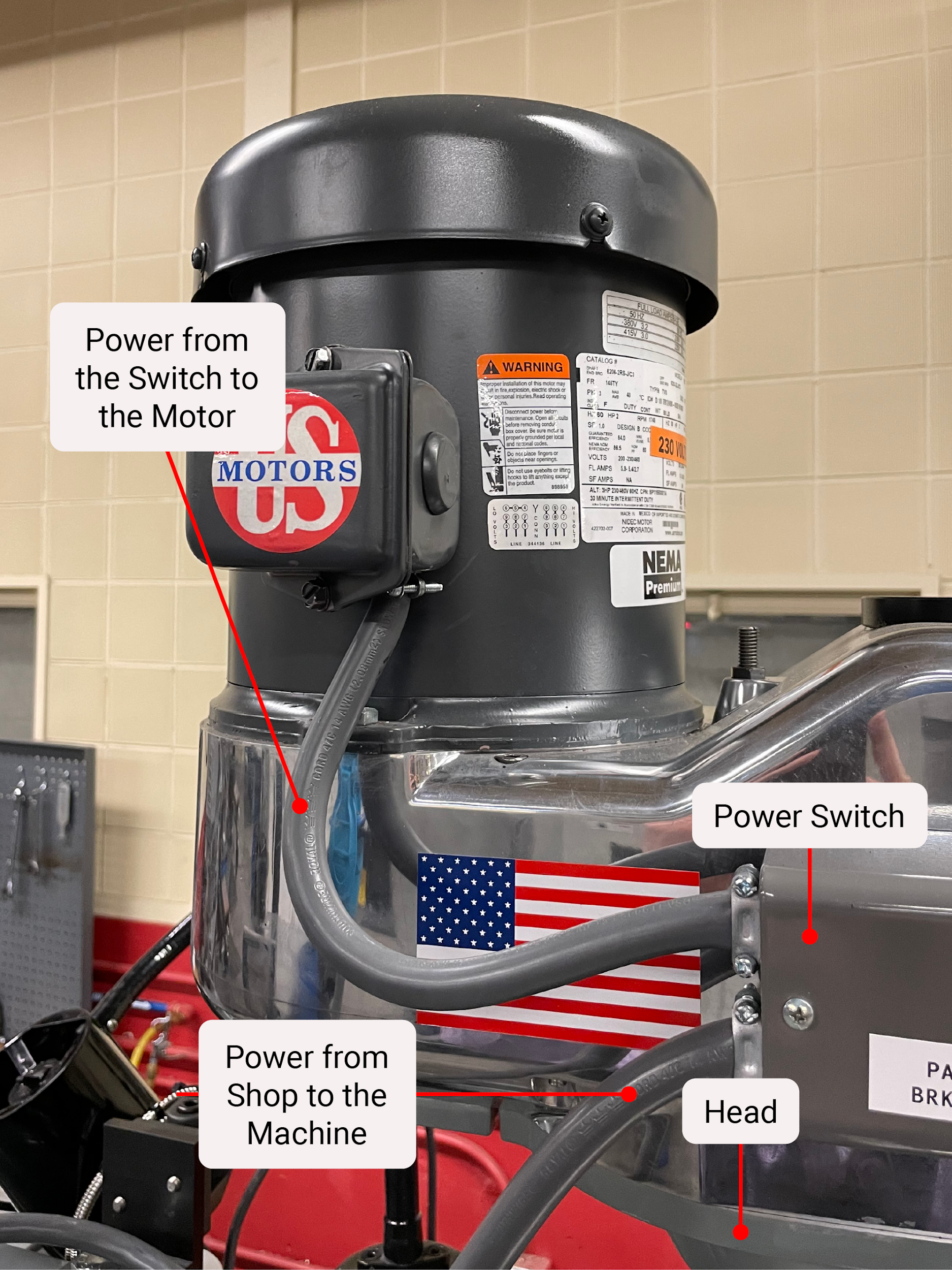
The motor is the main power source for the milling machine. The motor is connected to the spindle by way of belts and pulleys. Some machines require the operator to physically change the belts to different positions on stepped pulleys for RPM change, while others have a variable speed pulley that can change size with the turn of the spindle speed hand crank located on the front of the head.
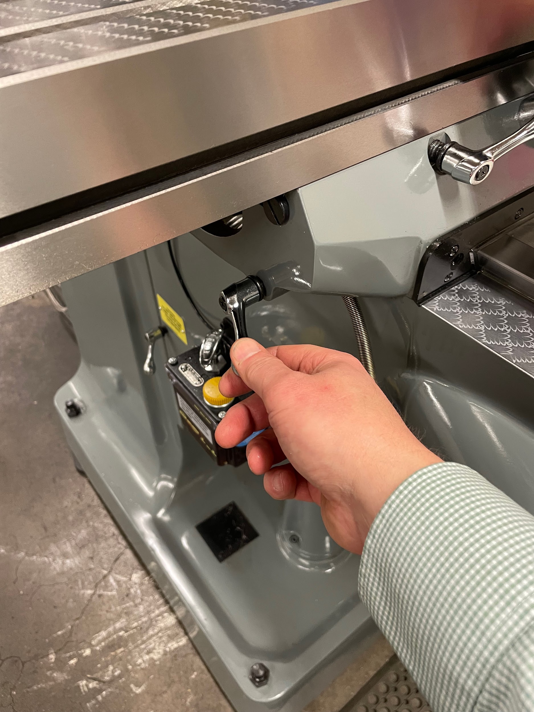
Knee
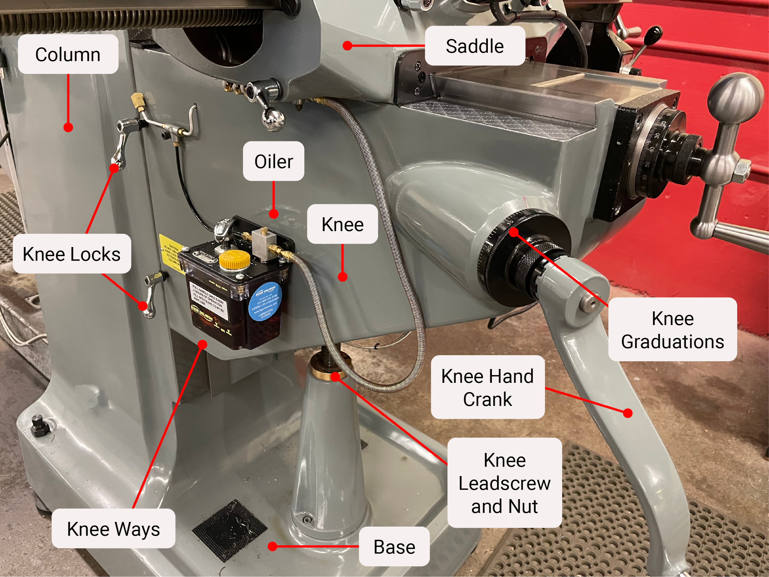
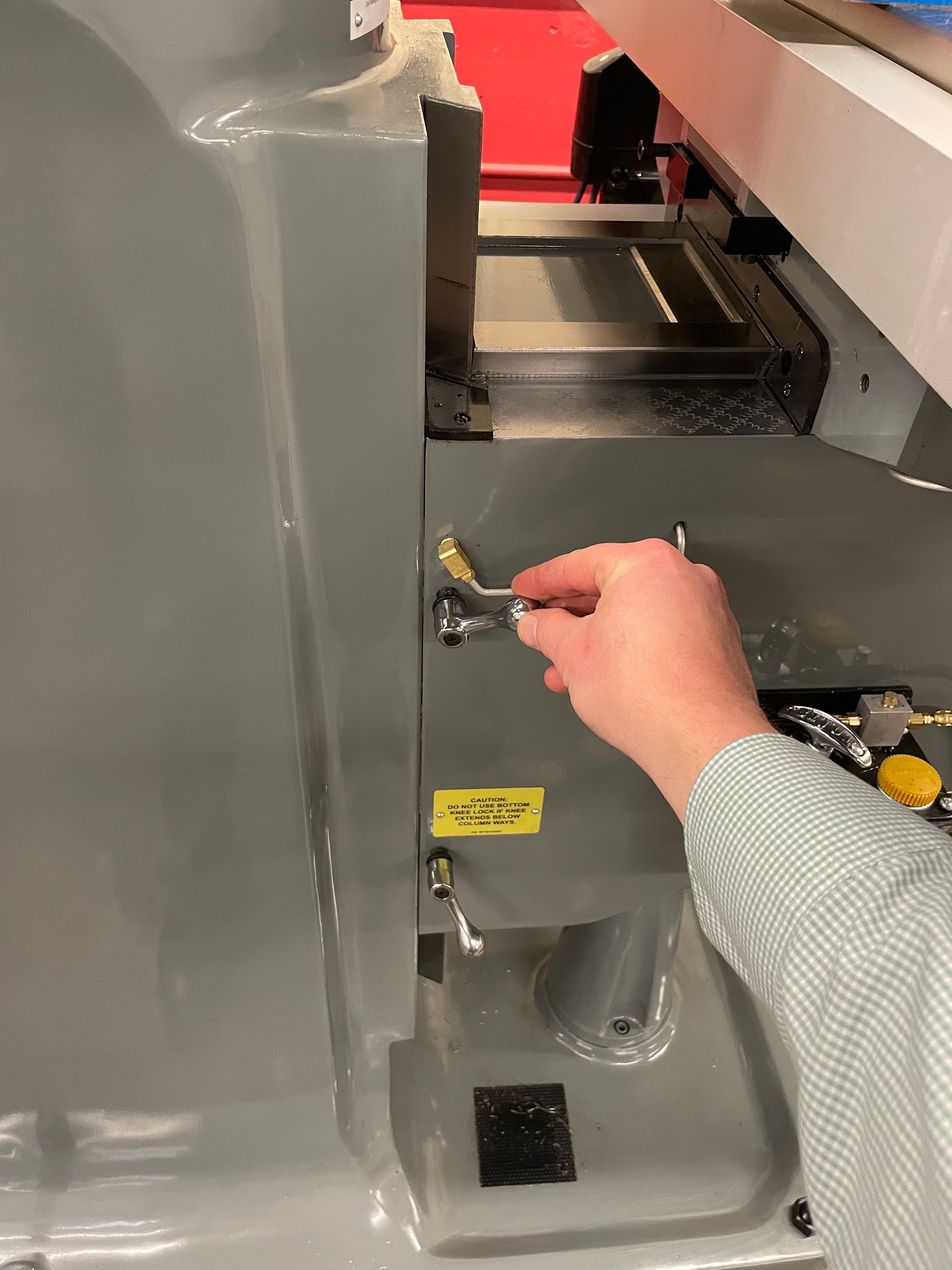
The knee of the milling machine rests on a screw that is attached to the base. The knee is attached to the column by precision ways. The screw and the ways allow for accurate up and down movement by way of a hand crank on the left side of the knee. One turn of the hand crank will raise or lower the knee by .100. The knee also contains the lead screw and ways that support the saddle.
Often when machinists are moving machine components, they are thinking of making movements in 3D space. The way the operator keeps track of the 3D movements is by using the Cartesian coordinate system. The knee moves the part up and down along the Z axis of the three-dimensional coordinate system.
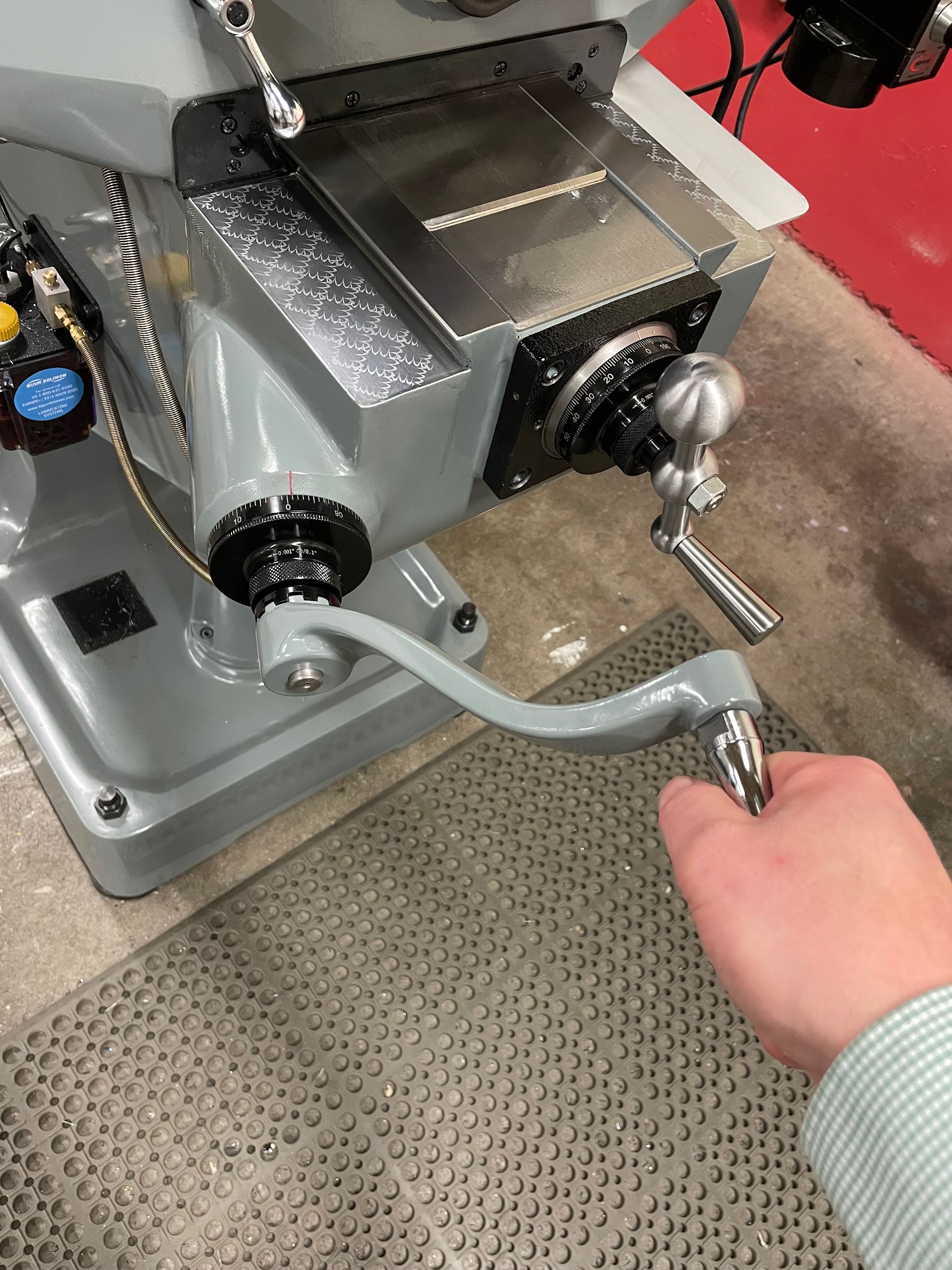
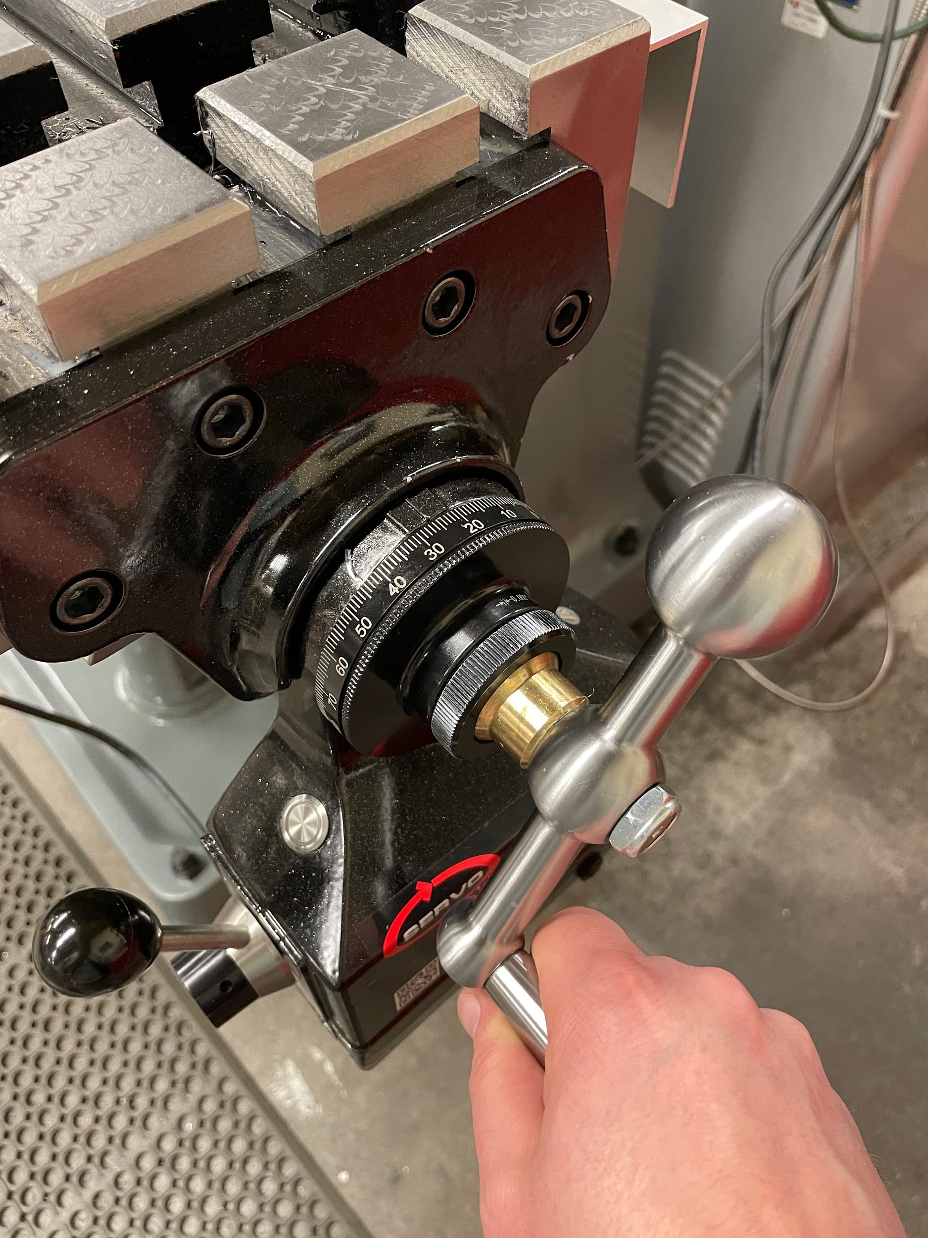
Saddle
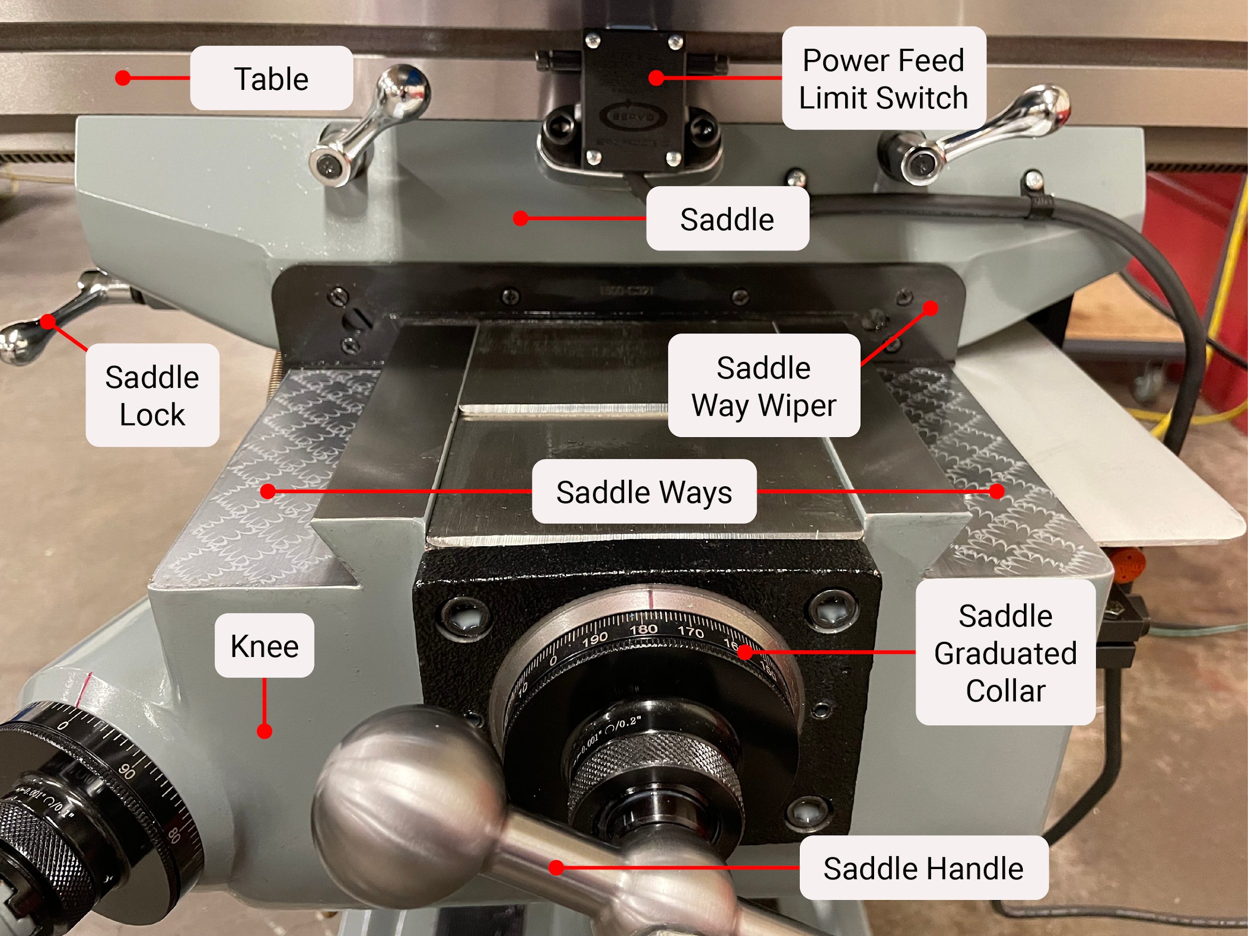
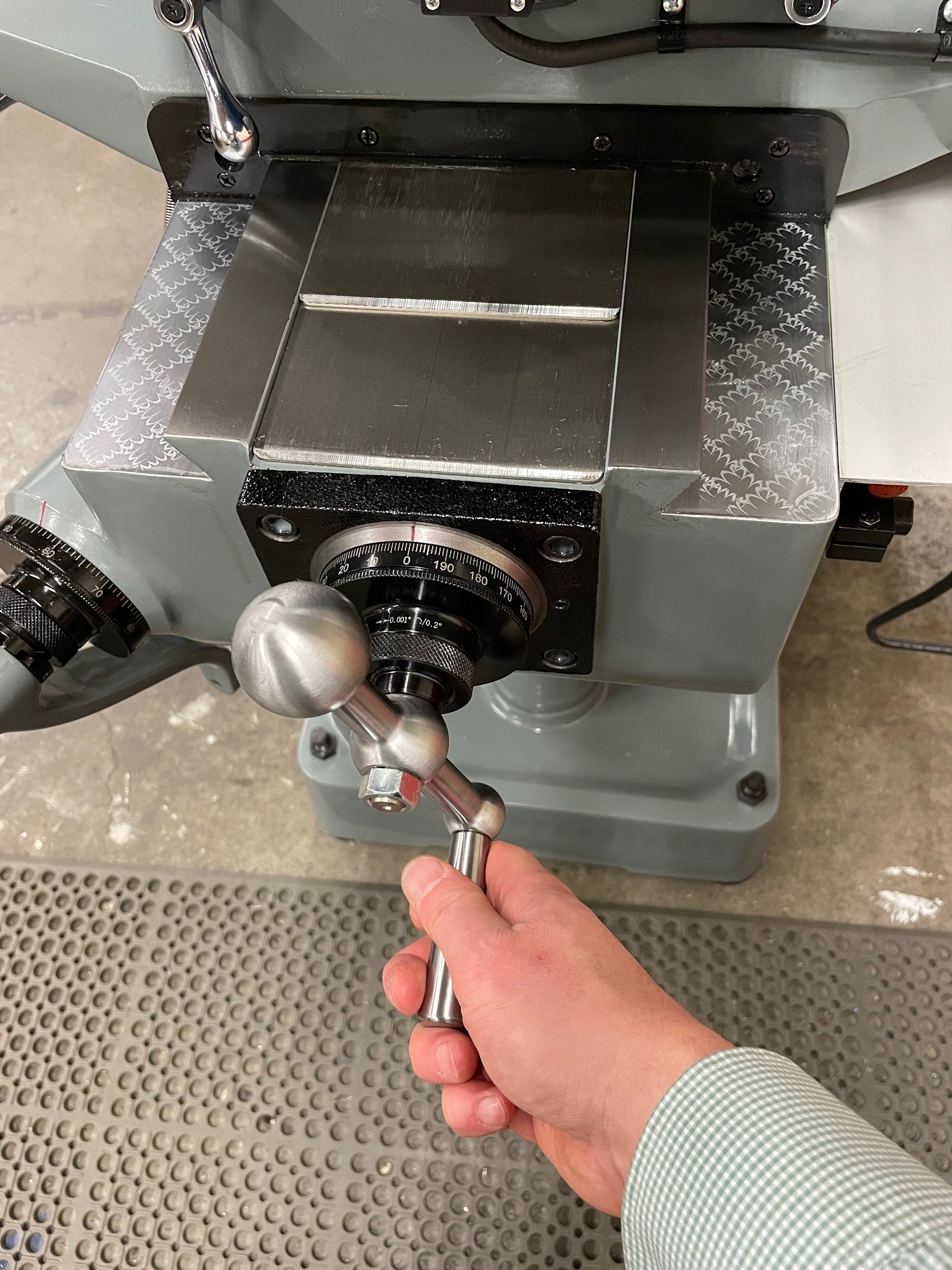
The saddle rests on ways at the top of the knee. These ways and a screw mechanism allow the saddle to accurately move in and out. One turn of the hand crank will move the saddle in and out by .200. At the top of the saddle are the ways that support the table movement. The saddle moves the part in and out along the Y axis of the three-dimensional coordinate system.
Table
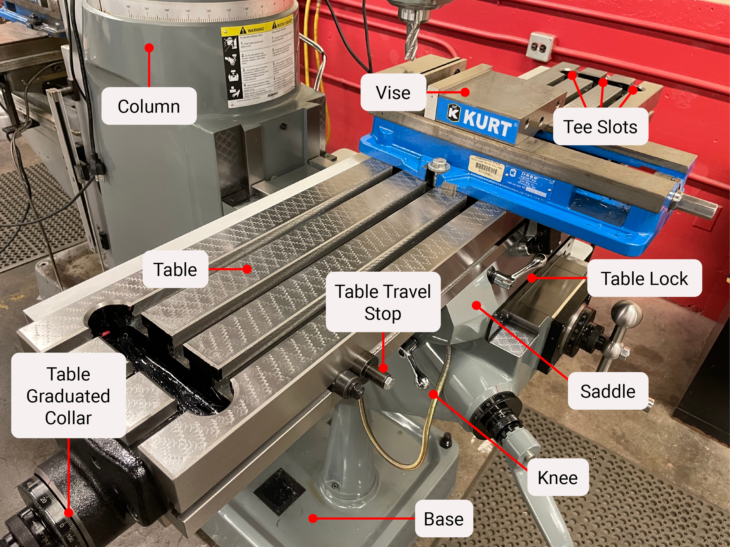
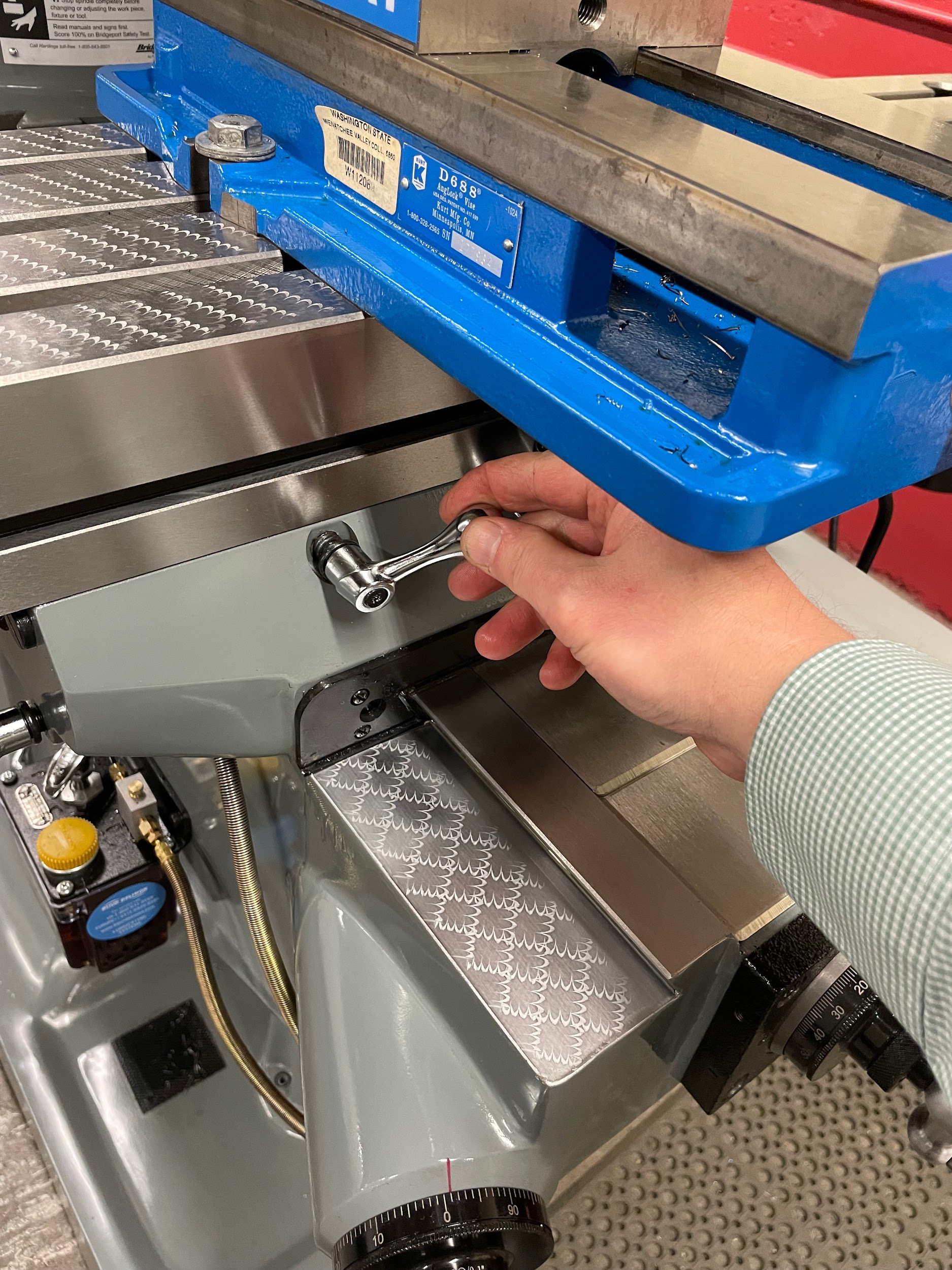
The table rests on ways at the top of the saddle. These ways and a screw mechanism allow the table to accurately move left and right. One turn of the hand crank will move the table side to side by .200. The table has tee slots to attach work holding accessories as well as allowing for direct work clamping. The table moves the part left and right along the X axis of the three-dimensional coordinate system.
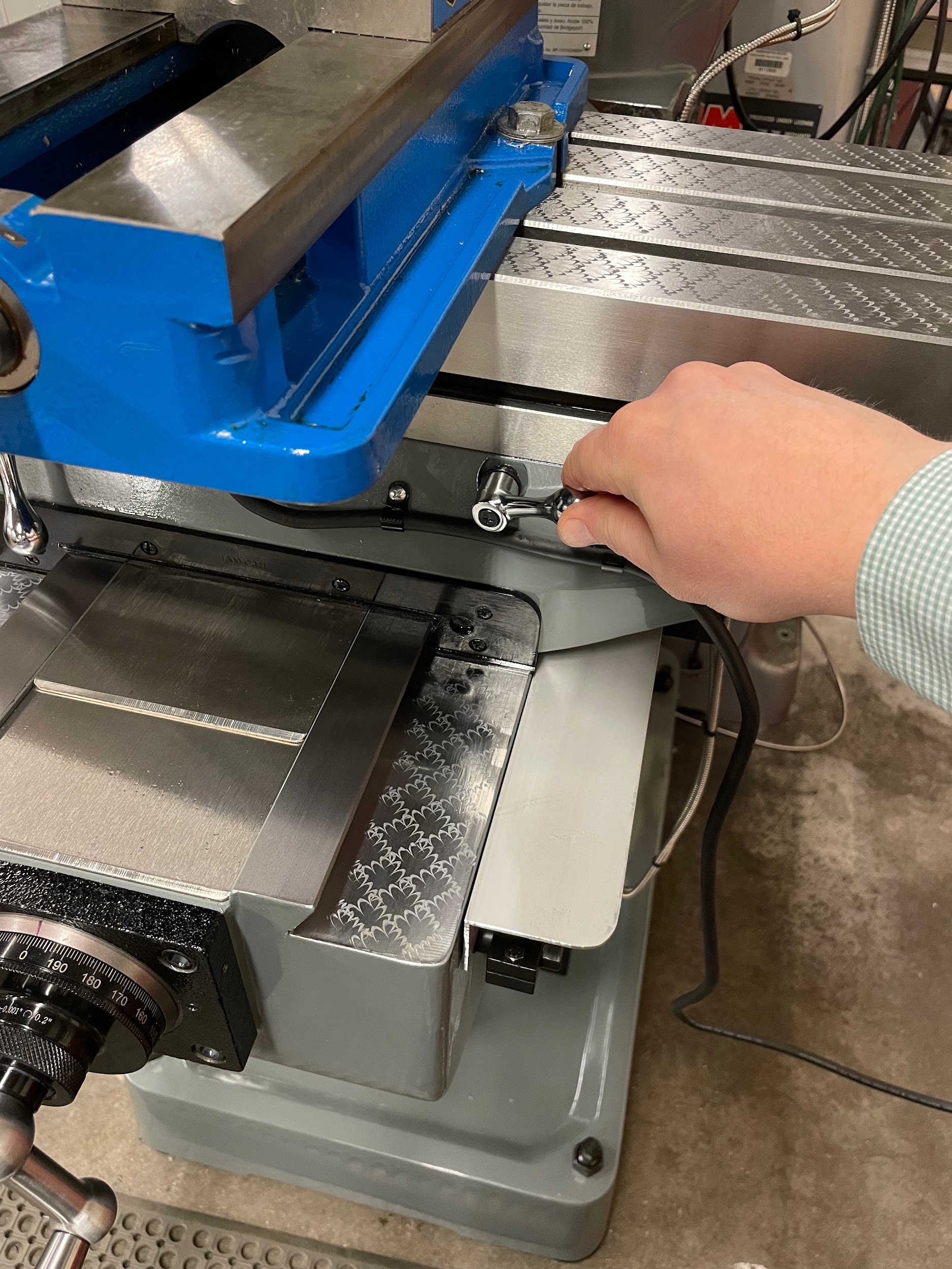
Power Feed
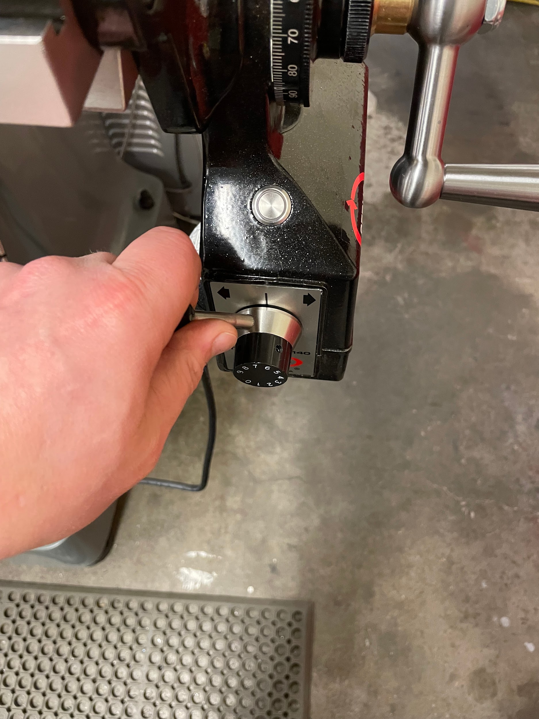
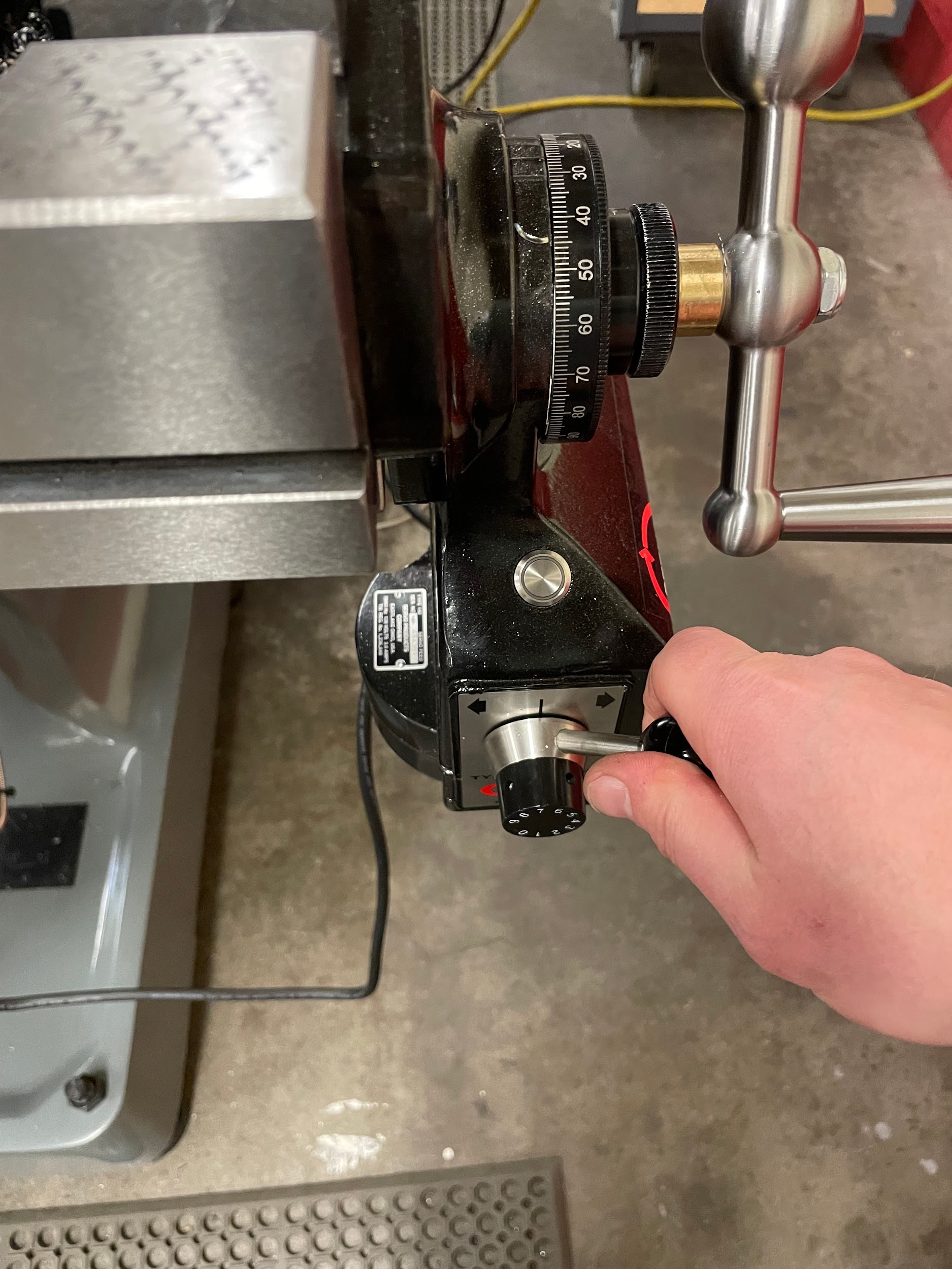
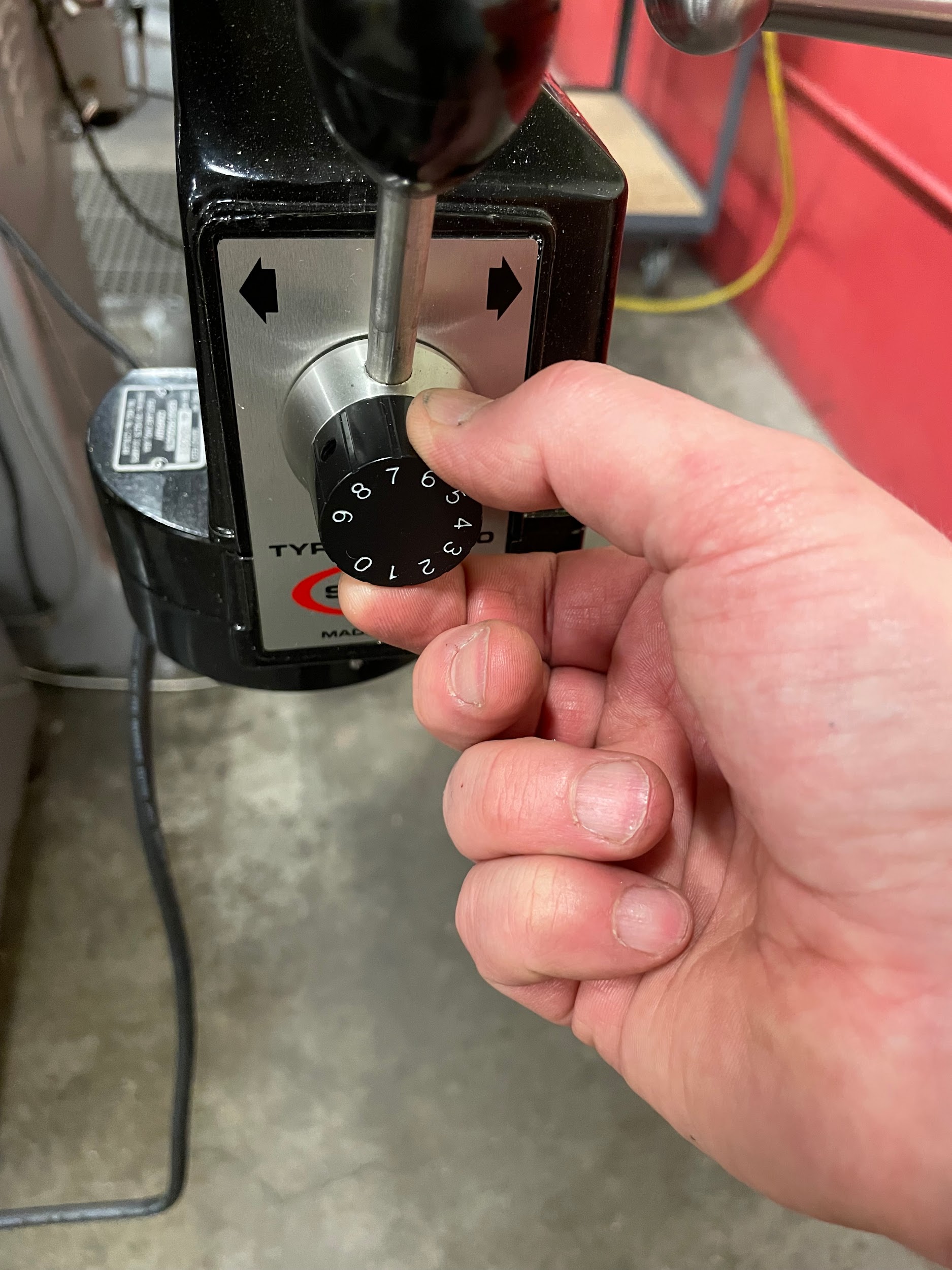
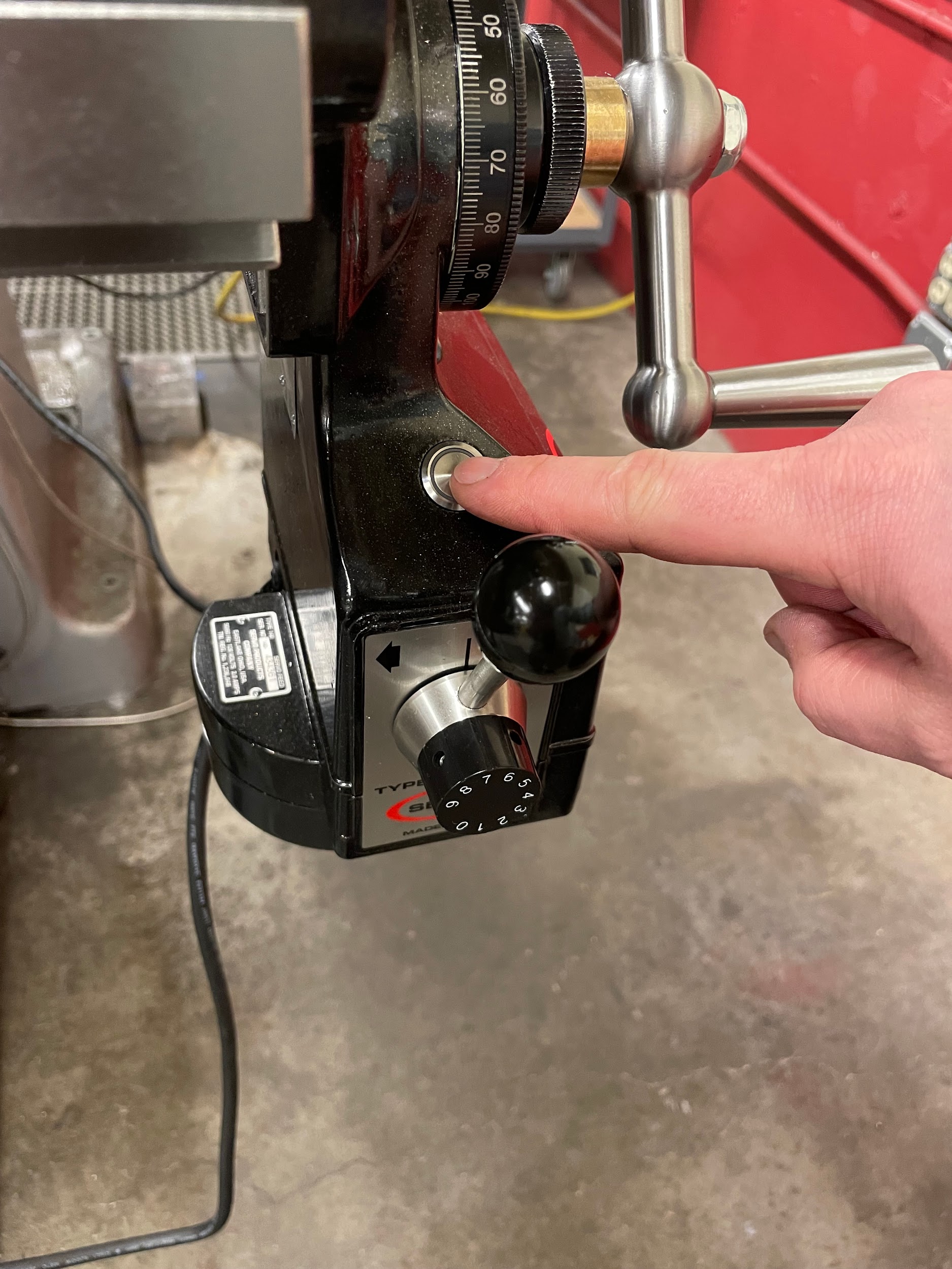
Power feed units on a milling machine control one or more of the three movable axes. The most common is mounted to the table and controls its side-to-side movement. The movement is determined by the push of a handle in the direction of the desired movement. Feed rate can be adjusted by turning the knob in the center of the directional handle. A rapid traverse button is located on the power feed body and can be used to quickly move from one point to another without adjusting the set feed rate.
Digital Readout (DRO)
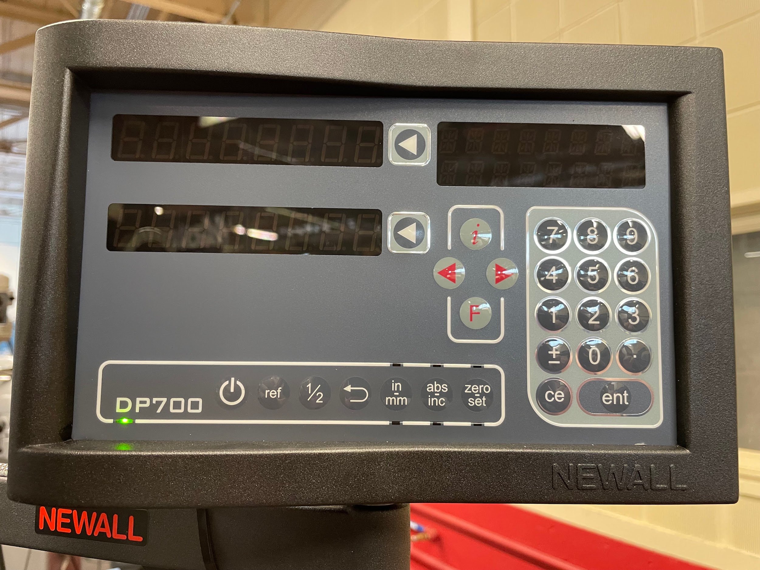
A digital readout (DRO) is a device that uses electronic scales to show the position of the machine digitally through a readout box. The DRO of a milling machine has two or three axes that it keeps track of. X is the side to side movement of the table, Y is the in and out motion of the saddle, and Z is the up and down movement of either the knee or the quill. X positive is towards the right side of the mill, Y positive is to the back of the mill, and Z positive is up with regard to the positioning of the tool. The readout can be easily zeroed at the push of a button, basically performing the action of zeroing the handwheel collars. They can also be set to whatever value the operator needs. The DRO has a few advantages over the traditional graduated collars:
- The operator does not have to keep track of multiple rotations of the handwheel. On large projects, it is easy to get lost. The DRO keeping track of all the operator’s movements is very helpful.
- The readout doesn’t change unless the table, saddle, knee, or quill moves. This means that the task of considering backlash when changing cut directions is eliminated.
- DROs have a finer resolution than graduated collars. The collars of the cross slide are often .002 in diameter for each graduation. On the carriage, the collar is often graduated in .005 increments. Most DROS have a resolution of .0005 or smaller. This makes it much easier to hold tight tolerances.
Modern DROs can do many different efficiency tasks that will not be covered in this text. An operator should consult their DRO operator’s manual for full details.
One disadvantage of a DRO is the cost. They cost several thousands of dollars to purchase, and hours of time to install. This is sometimes a larger cost than some smaller companies are able to incur. For this reason, all machinists should make sure they know how to operate equipment with the graduated collars.
Attributions
- Figure 9.11: Labeled manual vertical milling machine by Micky R. Jennings, courtesy of Wenatchee Valley College, for WA Open ProfTech, © SBCTC, CC BY 4.0
- Figure 9.12: Milling machine base by Micky R. Jennings, courtesy of Wenatchee Valley College, for WA Open ProfTech, © SBCTC, CC BY 4.0
- Figure 9.13: Column by Micky R. Jennings, courtesy of Wenatchee Valley College., for WA Open ProfTech, © SBCTC, CC BY 4.0
- Figure 9.14: Ram by Micky R. Jennings, courtesy of Wenatchee Valley College, for WA Open ProfTech, © SBCTC, CC BY 4.0
- Figure 9.15: Mill head by Micky R. Jennings, courtesy of Wenatchee Valley College, for WA Open ProfTech, © SBCTC, CC BY 4.0
- Figure 9.16: Mill head 2 by Micky R. Jennings, courtesy of Wenatchee Valley College, for WA Open ProfTech, © SBCTC, CC BY 4.0
- Figure 9.17: Motor by Micky R. Jennings, courtesy of Wenatchee Valley College, for WA Open ProfTech, © SBCTC, CC BY 4.0
- Figure 9.18: Knee by Micky R. Jennings, courtesy of Wenatchee Valley College, for WA Open ProfTech, © SBCTC, CC BY 4.0
- Figure 9.19: Knee crank by Micky R. Jennings, courtesy of Wenatchee Valley College, for WA Open ProfTech, © SBCTC, CC BY 4.0
- Figure 9.20: Knee locks by Micky R. Jennings, courtesy of Wenatchee Valley College, for WA Open ProfTech, © SBCTC, CC BY 4.0
- Figure 9.21: Saddle by Micky R. Jennings, courtesy of Wenatchee Valley College, for WA Open ProfTech, © SBCTC, CC BY 4.0
- Figure 9.22: Saddle handle by Micky R. Jennings, courtesy of Wenatchee Valley College, for WA Open ProfTech, © SBCTC, CC BY 4.0
- Figure 9.23: Saddle lock by Micky R. Jennings, courtesy of Wenatchee Valley College, for WA Open ProfTech, © SBCTC, CC BY 4.0
- Figure 9.24: Table by Micky R. Jennings, courtesy of Wenatchee Valley College, for WA Open ProfTech, © SBCTC, CC BY 4.0
- Figure 9.25: Table handle by Micky R. Jennings, courtesy of Wenatchee Valley College, for WA Open ProfTech, © SBCTC, CC BY 4.0
- Figure 9.26: Table lock by Micky R. Jennings, courtesy of Wenatchee Valley College, for WA Open ProfTech, © SBCTC, CC BY 4.0
- Figure 9.27: Table lock 2 by Micky R. Jennings, courtesy of Wenatchee Valley College, for WA Open ProfTech, © SBCTC, CC BY 4.0
- Figure 9.28: Power feed left by Micky R. Jennings, courtesy of Wenatchee Valley College, for WA Open ProfTech, © SBCTC, CC BY 4.0
- Figure 9.29: Power feed right by Micky R. Jennings, courtesy of Wenatchee Valley College, for WA Open ProfTech, © SBCTC, CC BY 4.0
- Figure 9.30: Feed rate adjustment by Micky R. Jennings, courtesy of Wenatchee Valley College, for WA Open ProfTech, © SBCTC, CC BY 4.0
- Figure 9.31: Rapid by Micky R. Jennings, courtesy of Wenatchee Valley College, for WA Open ProfTech, © SBCTC, CC BY 4.0
- Figure 9.32: Digital readout by Micky R. Jennings, courtesy of Wenatchee Valley College, for WA Open ProfTech, © SBCTC, CC BY 4.0
The bottom feature of a piece of machinery, often attached to the floor.
A vertical component of machinery that extends from the base to other components.
The component of a milling machine that sits on top of the column and provides an attachment point for the head.
The component of a machine that contains the spindle.
The component of a machine that provides the power for machining operations.
The component of a milling machine that attaches to the column and provides an attachment point for the saddle.
The component of a milling machine that attaches to the knee and provides an attachment point for the table.
The component where material or a work holding device is placed, on a machine tool.
A device that applies a consistent mechanized rate to the movement of machine tools.
