9.5 Work Setup
Micky R. Jennings
Setting up the work on a milling machine could be as easy as clamping a piece of material into a vise; however, sometimes there is more to it. Sometimes the angle of the head needs to be adjusted, and sometimes the machinist needs to know the exact center of the work or just a couple edges. The operator of the mill must know how to perform all of these setup configurations and more. Following a work plan and studying the print are the first steps to deciding which work setup is right for each operation.
Tramming the Mill Head
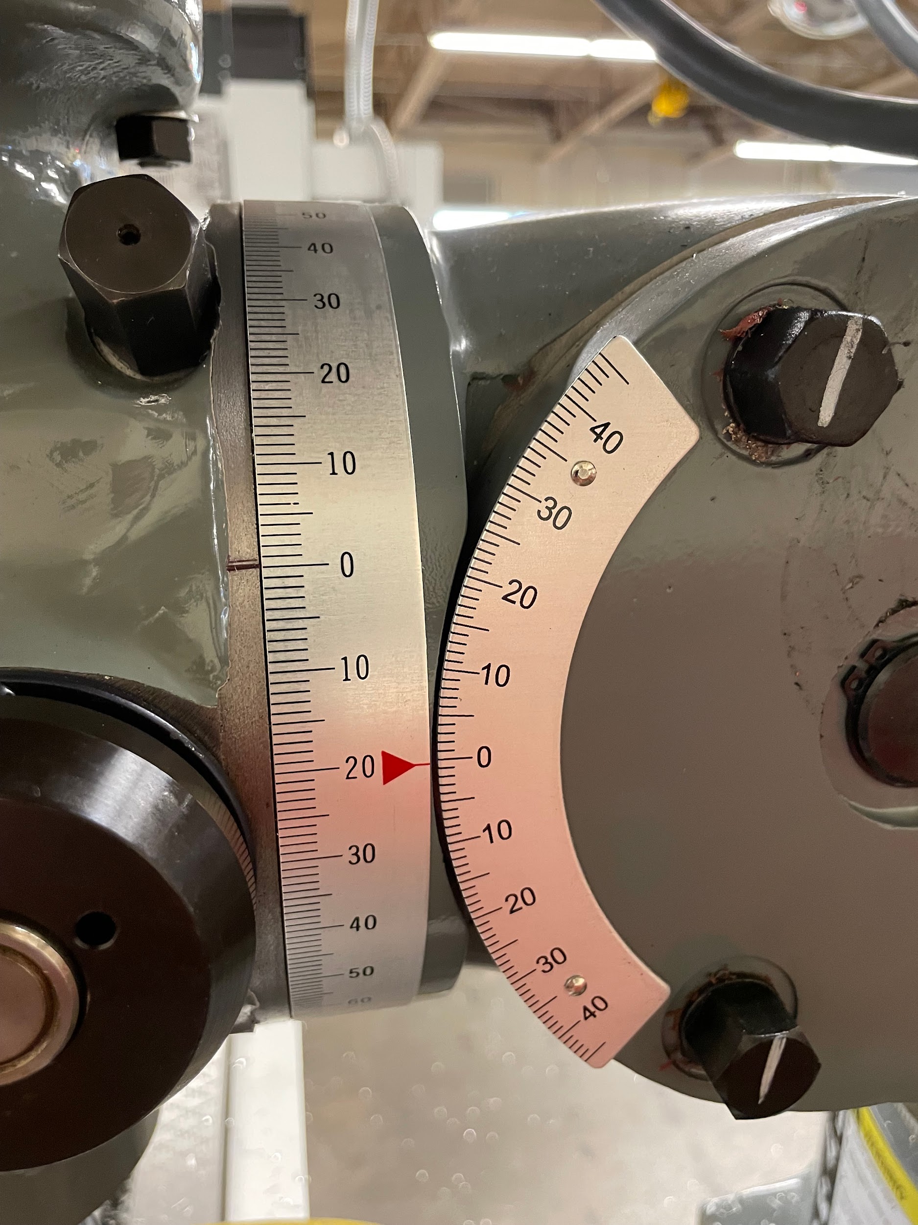
Tramming the head of a milling machine is the process of aligning the rotational axis of the spindle to be perpendicular to the table. The tramming process is carried out by adjusting the tilting and nodding functions of the joints in between the head and the ram. The amount the head is out of tram can be measured by attaching indicators to the spindle, rotating it to different points on the table, and reading the difference in the values on the indicator.
Step by step process for checking and tramming the milling head:
- Remove the vise.
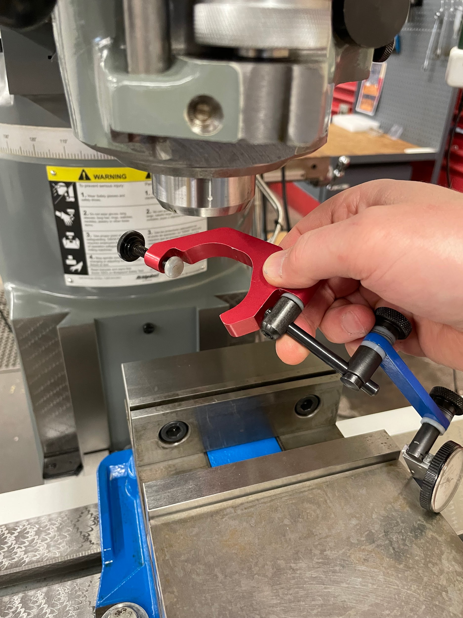
- Place a tramming device into or onto the spindle of the milling machine. This device should have at least a 4″ reach from the center of the spindle.
- Install an indicator on the tramming device.
- Place the spindle in neutral. This is for ease of movement.
- Center the table.
- Raise the quill to the top of its travel and lock it.
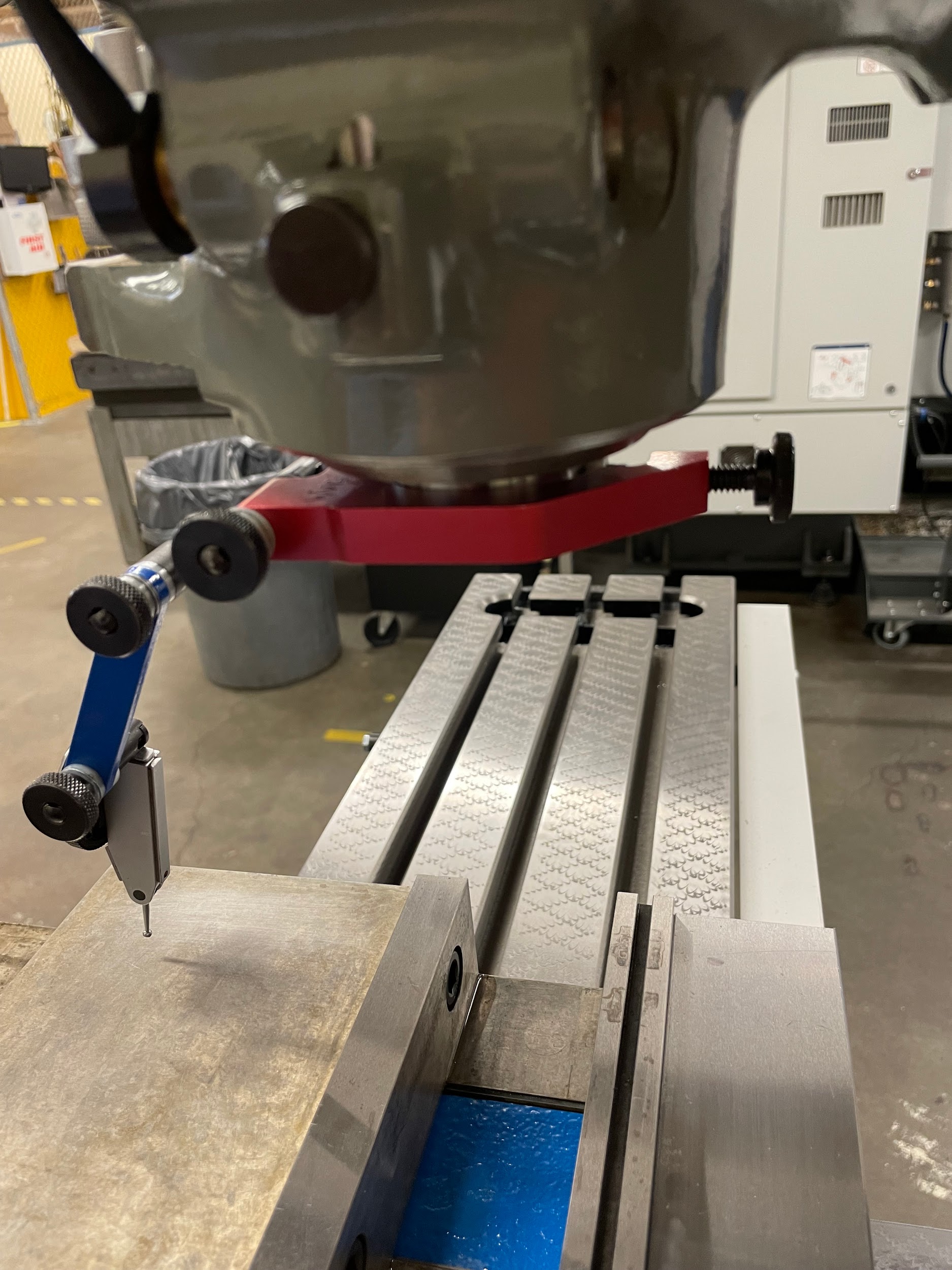
- Raise the knee, so the table comes up and into the motion of the indicator and lock it. Generally, about .020 is enough. Too much indicator preload may harshly bump the indicator as it travels across the tee slots, potentially altering its readings and position.
- Move the spindle so the tip of the indicator does not fall into a scraping mark or damaged spot.
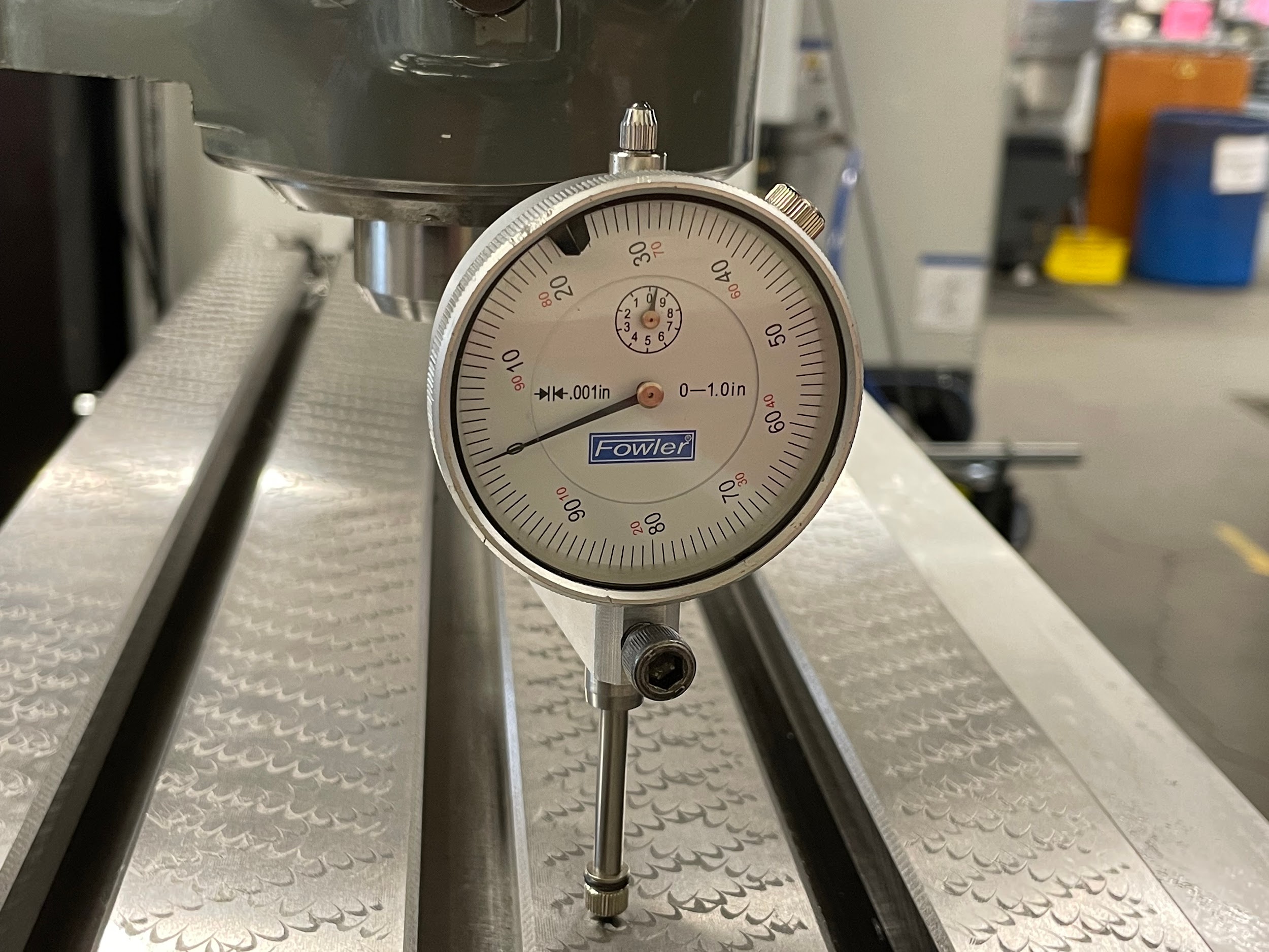
- Zero the indicator.
- Slowly rotate the spindle around the table, checking opposing directions to determine if the tilt or nod may need adjustment.
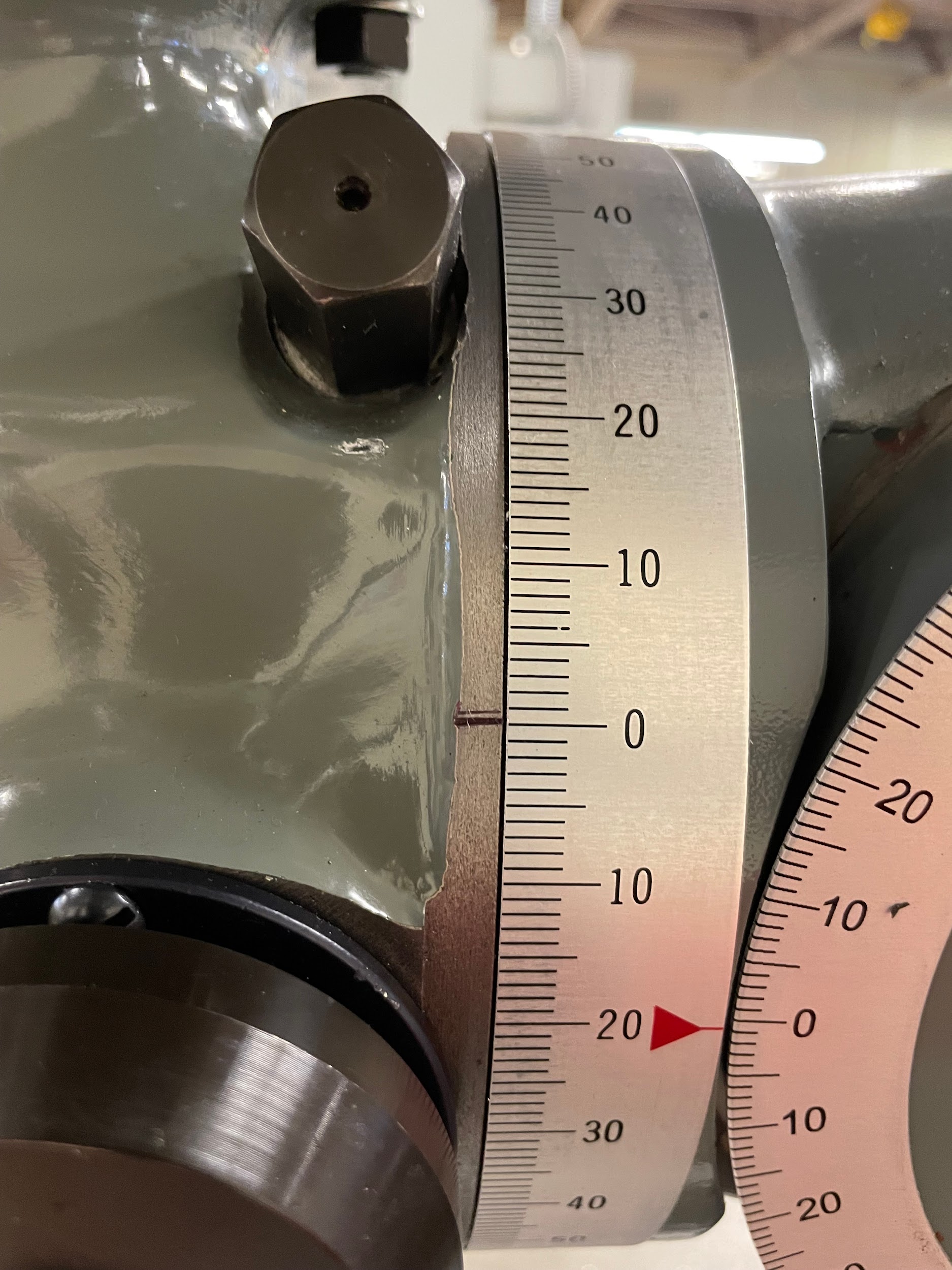
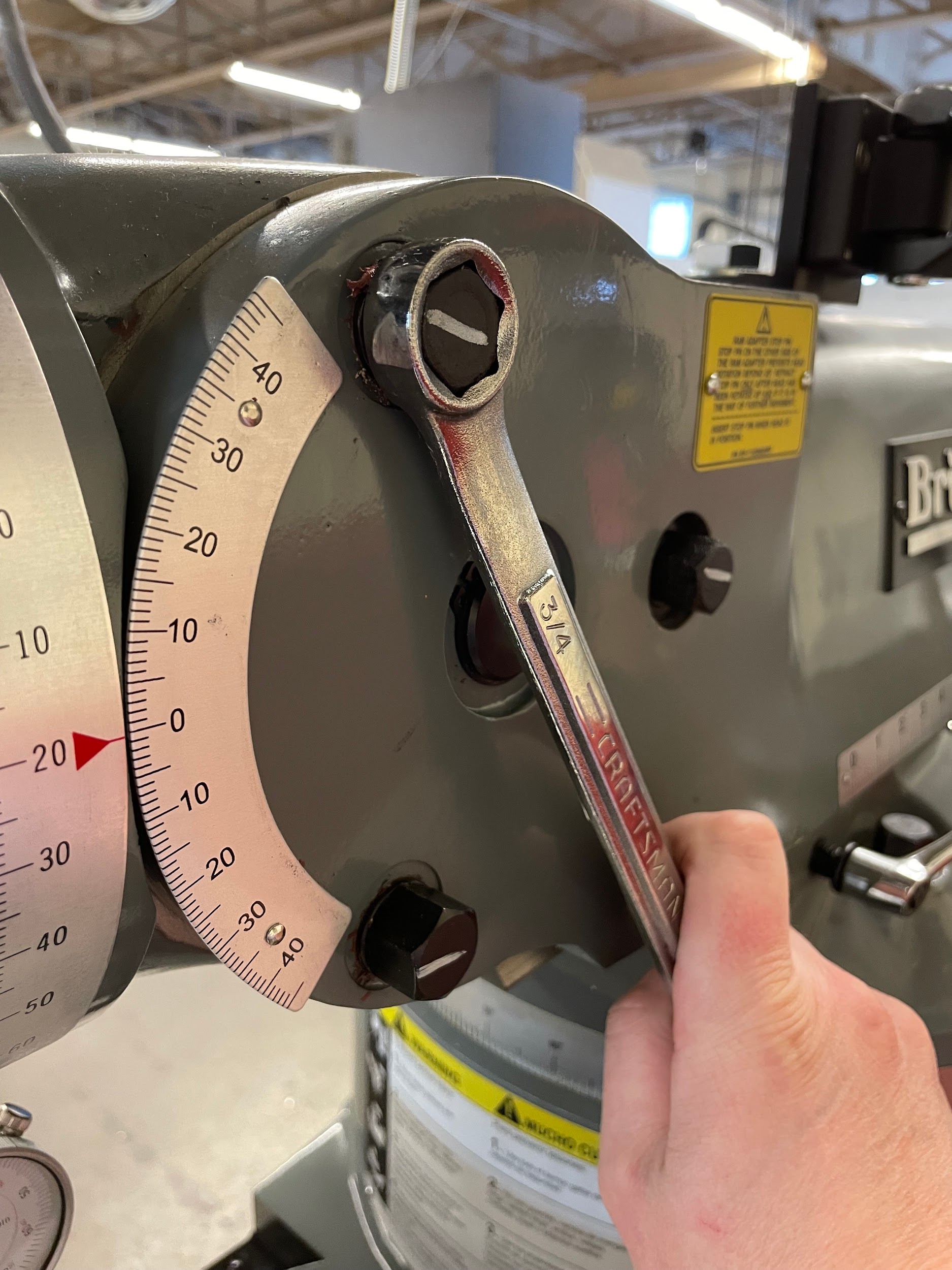
- The direction most out of tram should be addressed first. For this demonstration, the tilt will be adjusted first because it is slightly easier than the nod.
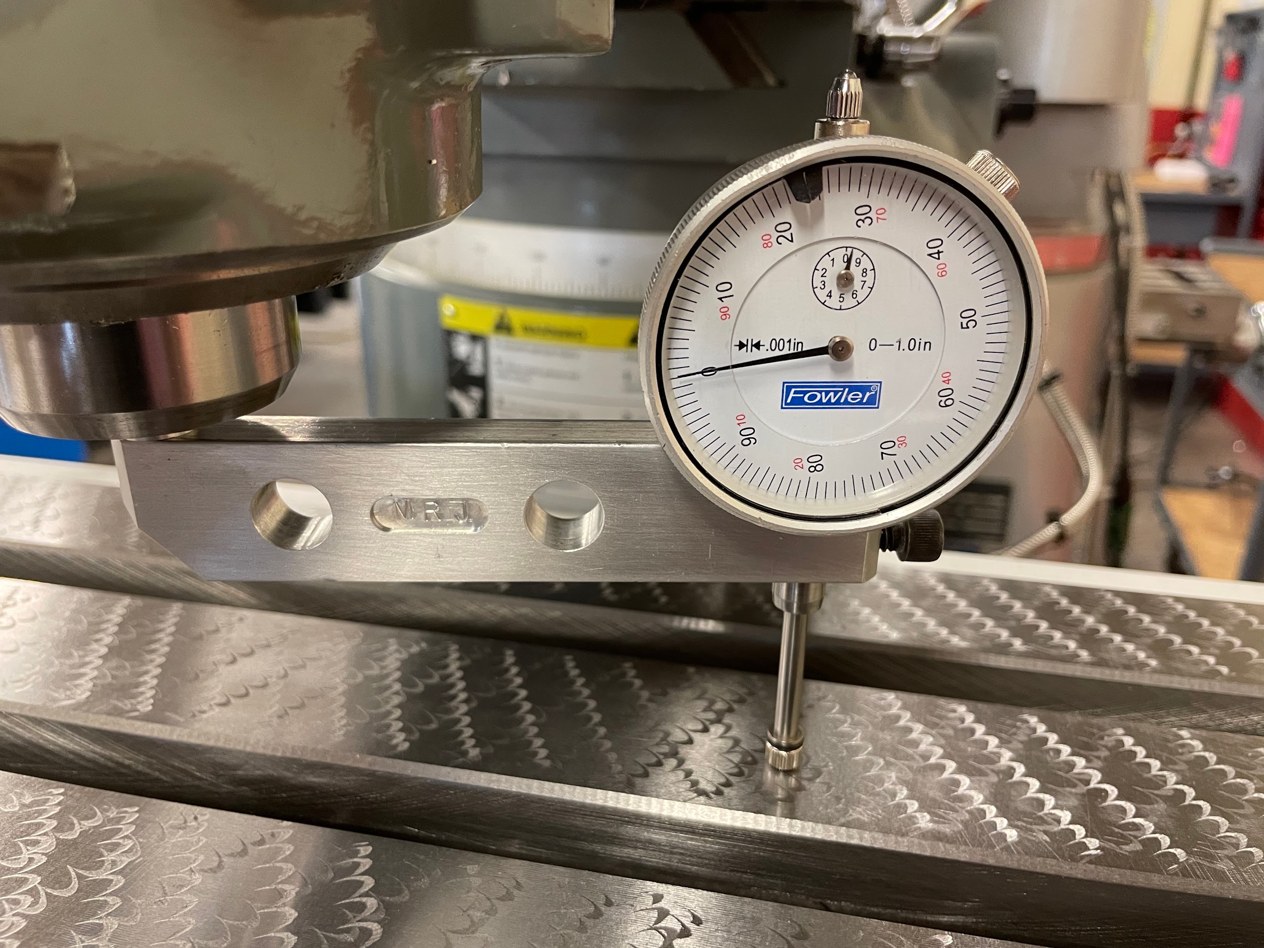
- Rotate the spindle to the furthest left and check the indicator reading. The difference between the right and left sides is the amount out of tram in the side to side tilting motion. If the difference from one side to the other is more than .001, the tilt must be adjusted.
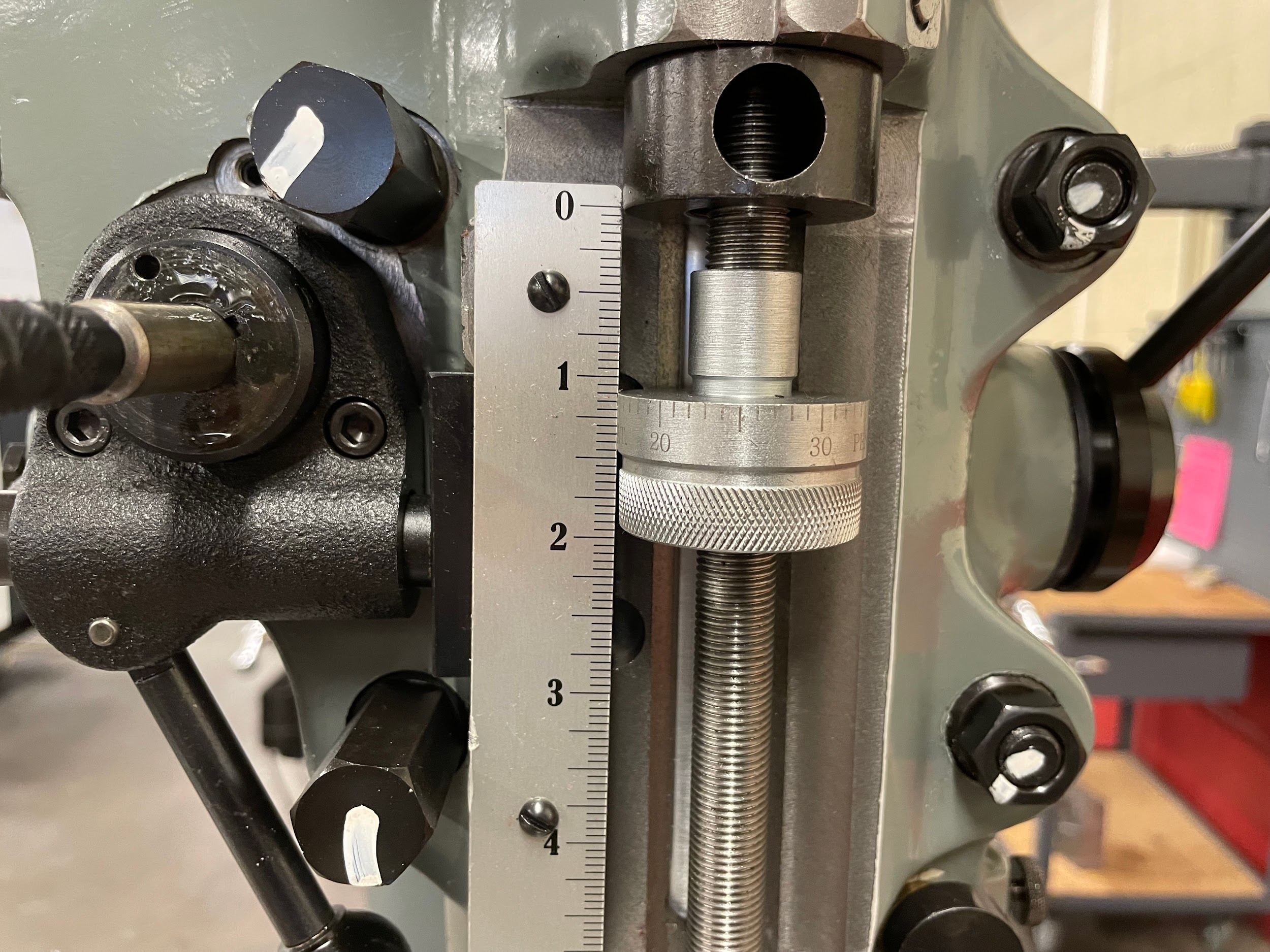
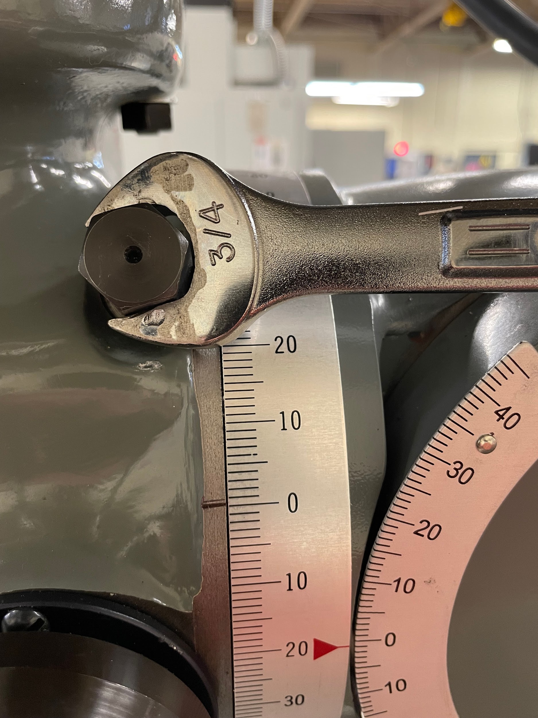
- Start by loosening the four fasteners on the face of the milling head.
- Adjust the tilt by half the amount the head is out of tram in the side to side direction. This is possible because the pivot point is in the middle of the two indicator positions. As one indicator reading gets smaller, the other one gets larger until they meet.
- Tighten the four fasteners to 50 ft./lbs.
- Recheck the tilt tram. If it is still out, repeat the process of adjusting.
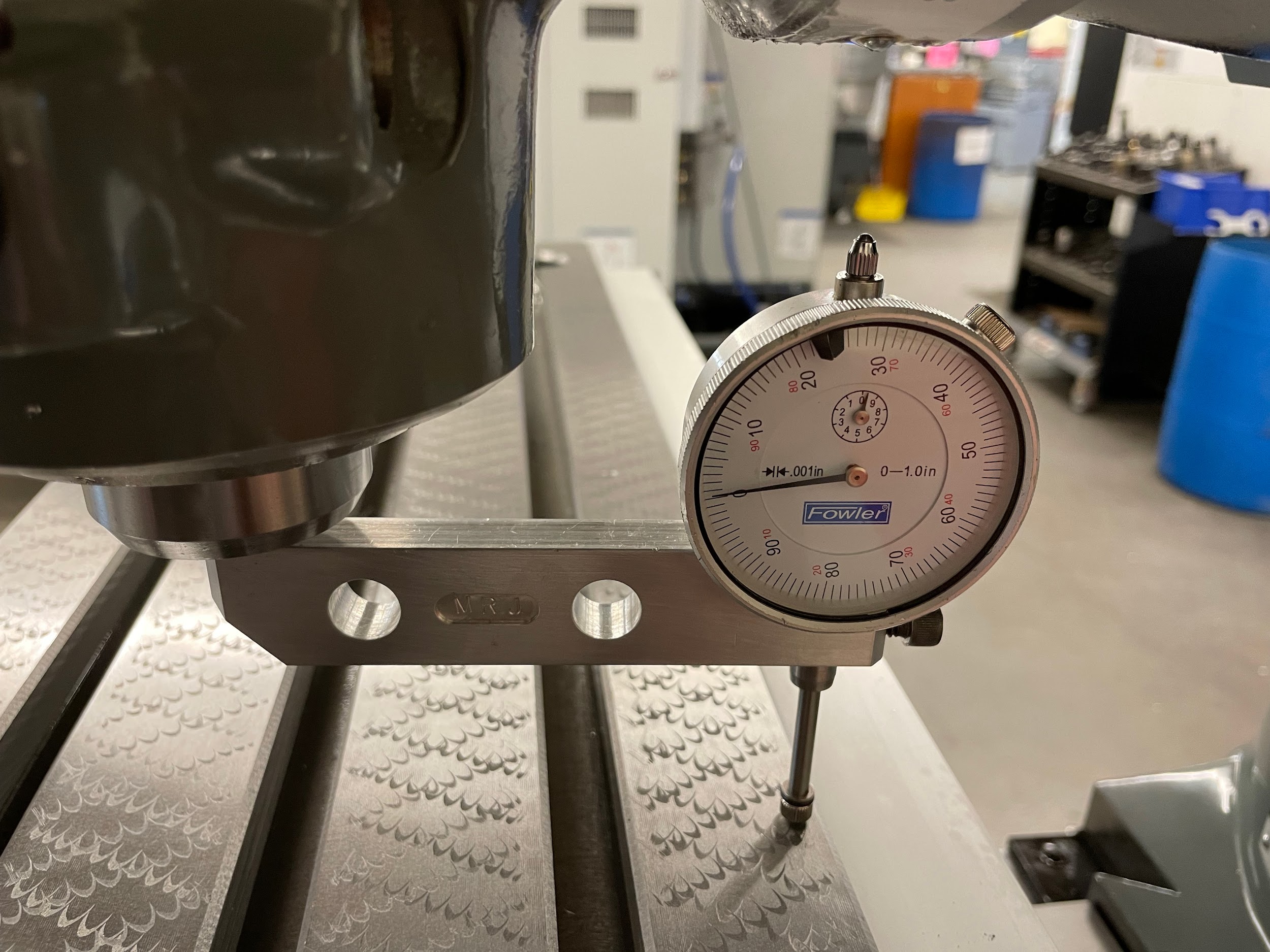
- Rotate the spindle and move the indicator to the front of the table.
- Zero the indicator again.
- Rotate the spindle and move the indicator to the back of the table. The difference between the front and back is the amount out of tram in the up and down nodding motion. If the difference from front to back is more than .001, the nod must be adjusted.
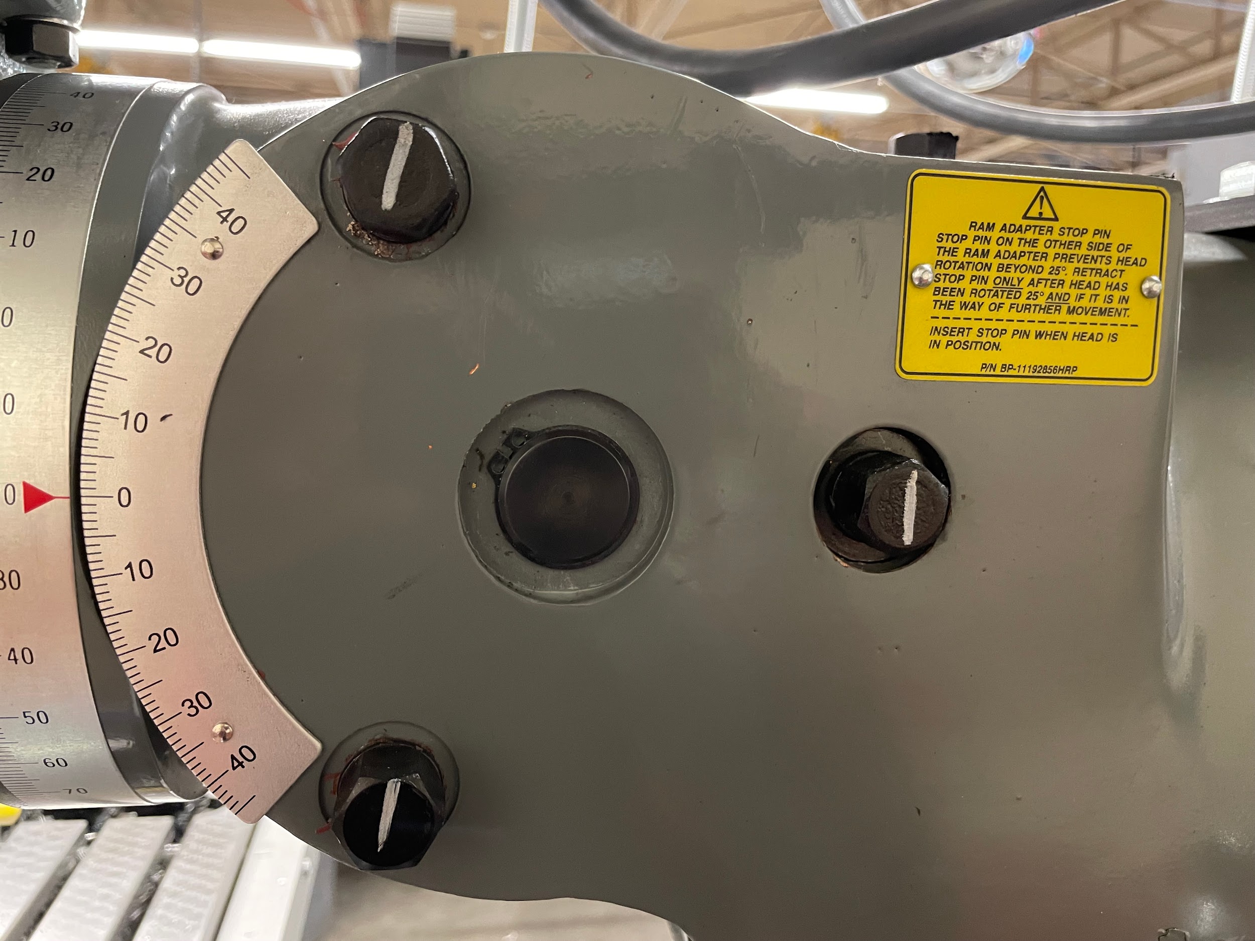
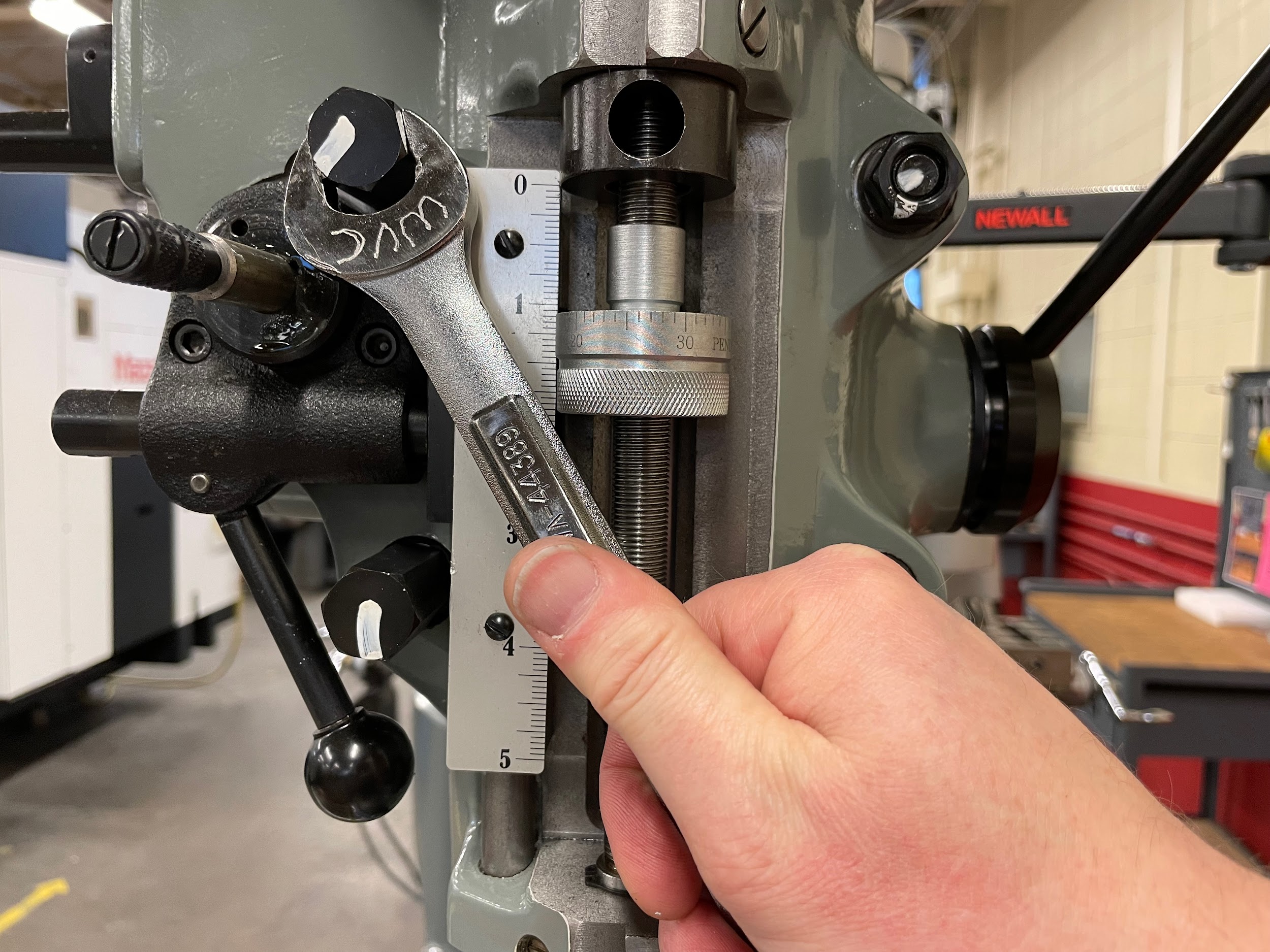
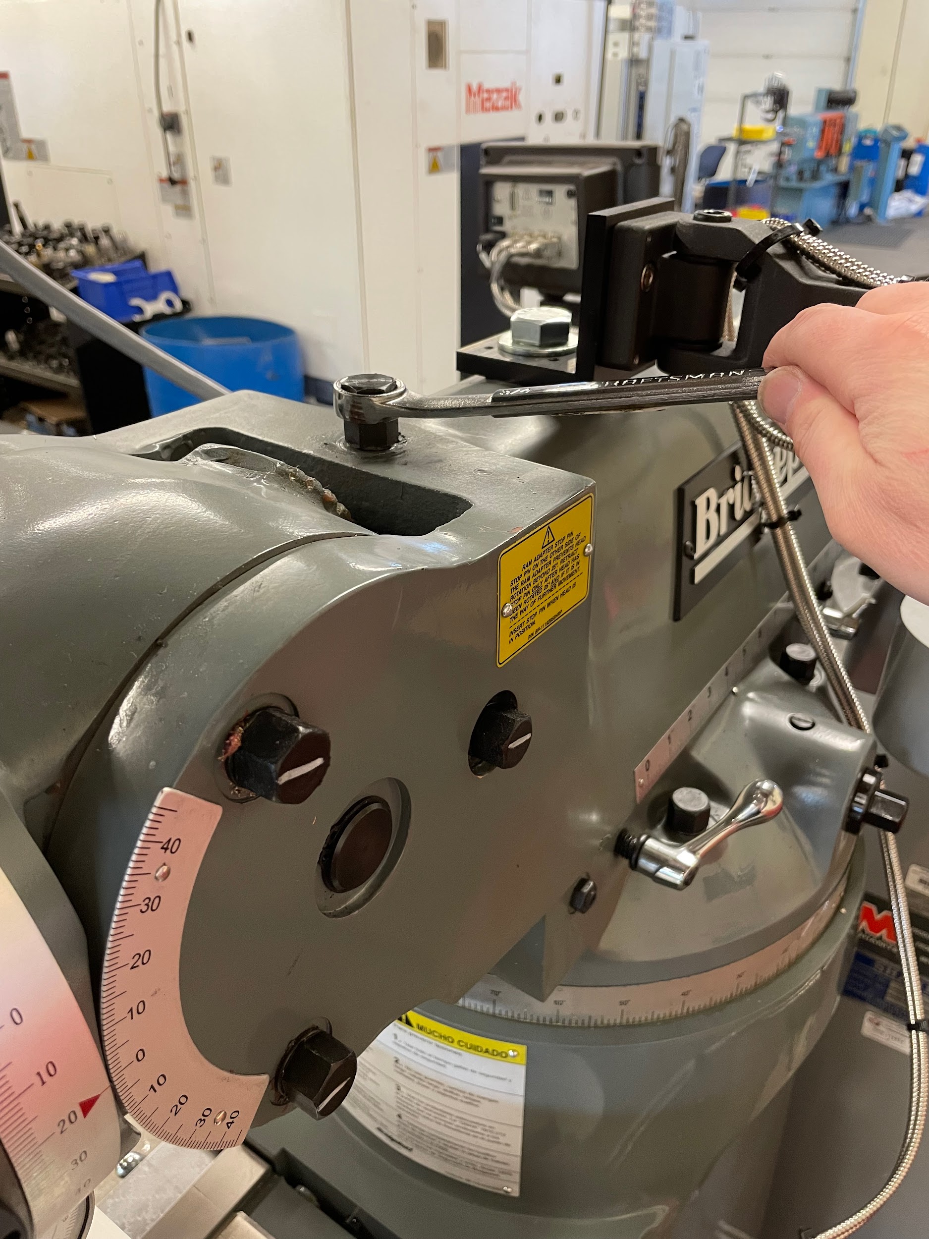
- Start by loosening the three (sometimes six) fasteners on the side of the milling head at the ram.
- Adjust the nod. The nod is more difficult to adjust because the pivot point is further away, and it can’t just be adjusted to the middle of the two indicator readings because with each nod adjustment, both indicator readings will move in the same direction. They move in the same direction, but at a different rate. The indicator position furthest away from the pivot point will move faster than the indicator reading that is closer to the pivot point.
- Tighten the three (possibly six) fasteners to 50 ft./lbs.
- Recheck the nod tram. If it is still out, repeat the process of adjusting.
- When the head is in tram, the indicator will read the same at all four points on the table. It may take measuring and adjusting both the tilt and nod multiple times before the head is in tram, as adjusting one may affect the other.
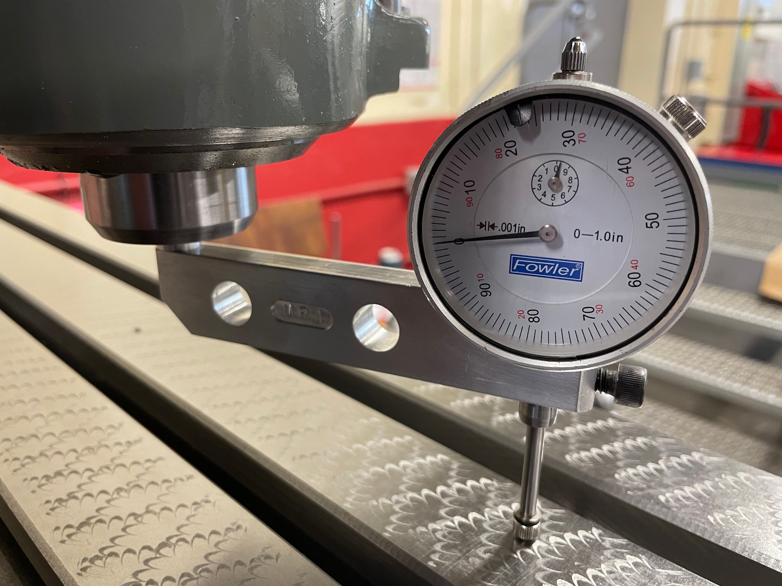
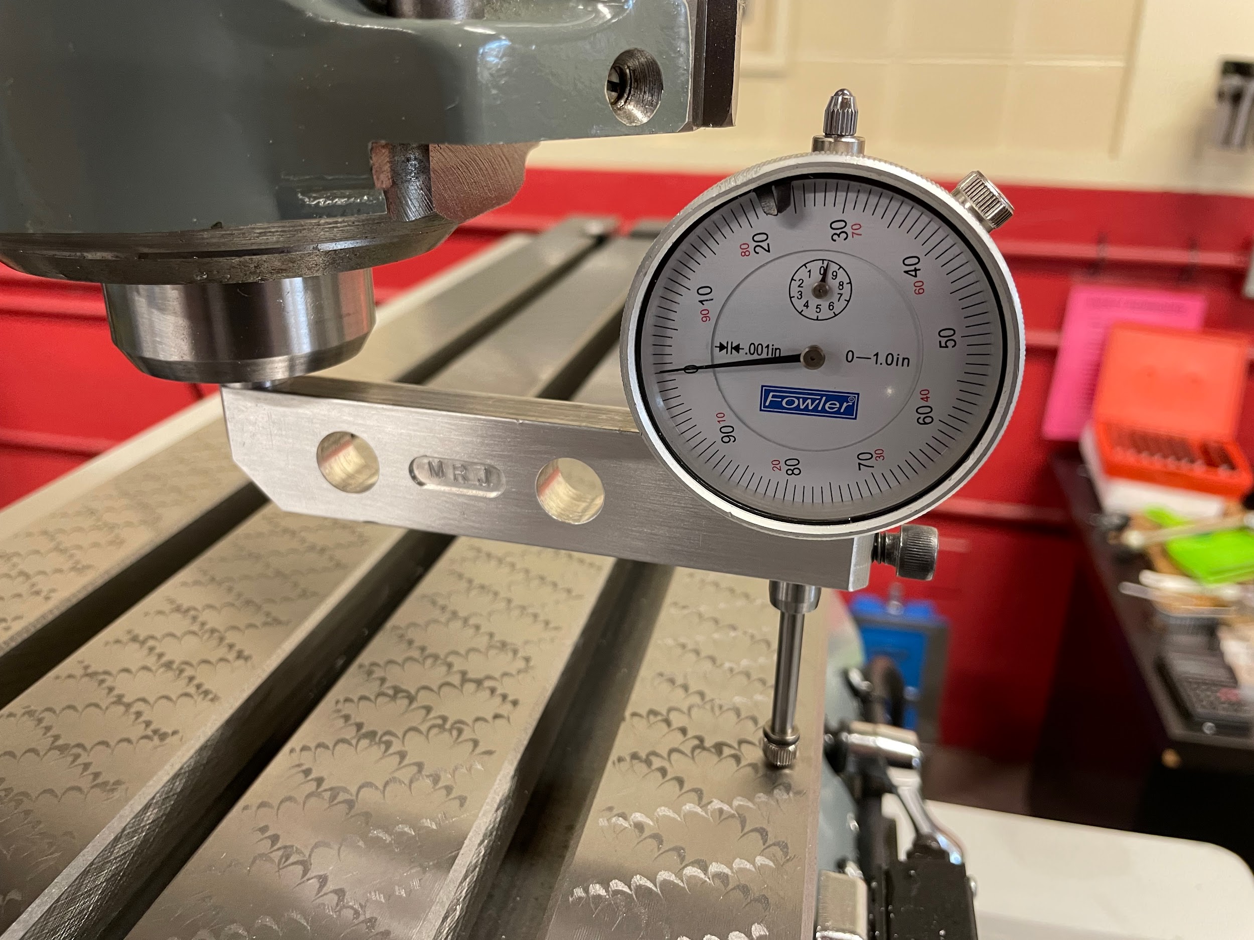
Step 7-9: Raise the knee so the table comes up and into the motion of the indicator and lock it. Generally, about .020 is enough. Too much indicator preload may harshly bump the indicator as it travels across the tee slots, potentially altering its readings and position. Move the spindle so the tip of the indicator does not fall into a scraping mark or damaged spot. Zero the indicator.

Step 9: Zero the indicator.
Step 10: Slowly rotate the spindle around the table, checking opposing directions to determine if the tilt or nod may need adjustment.

Step 10: Slowly rotate the spindle around the table, checking opposing directions to determine if the tilt or nod may need adjustment.

Step 10: Slowly rotate the spindle around the table, checking opposing directions to determine if the tilt or nod may need adjustment.

Step 13: Start by loosening the four fasteners on the face of the milling head.
Step 14: Adjust the tilt by half the amount the head is out of tram in the side-to-side direction. This is possible because the pivot point is in the middle of the two indicator positions. As one indicator reading gets smaller, the other one gets larger until they meet.
Step 16: Recheck the tilt tram. If it is still out, repeat the process of adjusting.
Step 16: Recheck the tilt tram. If it is still out, repeat the process of adjusting.
Step 20: Start by loosening the three (sometimes six) fasteners on the side of the milling head at the ram.
Step 21: Adjust the nod. The nod is more difficult to adjust because the pivot point is further away, and it can’t just be adjusted to the middle of the two indicator readings because with each nod adjustment, both indicator readings will move in the same direction. They move in the same direction, but at a different rate. The indicator position furthest away from the pivot point will move faster than the indicator reading that is closer to the pivot point.
Step 23: Recheck the nod tram. If it is still out, repeat the process of adjusting.
Step 23: Recheck the nod tram. If it is still out, repeat the process of adjusting.
Step 24: When the head is in tram, the indicator will read the same at all four points on the table. It may take measuring and adjusting both the tilt and nod multiple times before the head is in tram, as adjusting one may affect the other.

Author’s Tip
- When tramming in a mill head, take special precaution to not loosen the fasteners too much. If they are too loose, the head will abnormally sag, and it will be more difficult to adjust the movement precisely. Loosen one at a time, loosening it all the way, and then retightening it just a little bit. Tighten it until the fastener is a little tighter than finger tight. Just enough to take all the available slack out of the fastener, but not enough that the head will not move. This allows for a more precise adjustment at the proper position of the head.
- When tilting the machine head, there may be a safety device that has to be removed to allow you to tilt beyond a certain point. This is because the worm drive mechanism isn’t strong enough to move the head back from this point. If you attempt to pull the head back into place with the worm drive mechanism, it will break, and the head will drop violently against the table or side of the mill. In order to do this properly, the operator must help by lifting the head with one hand and turning the adjustment worm gear with the other. The worm gear is designed to hold the head in place, and to make fine adjustments when in a balanced upright position, but it is not strong enough to lift the head from a near horizontal position.
Replacing Vise Jaw Plates
On occasion, the vise jaw plates need to be removed and replaced. Sometimes this is to install soft jaw plates; other times, the operator may want to put on a pair of stepped jaw plates or mount the jaw plates on the other side of the jaws to grip larger work. Whatever the reason, this is a common operation for the machinist to perform.
Step by step process for replacing jaw plates:
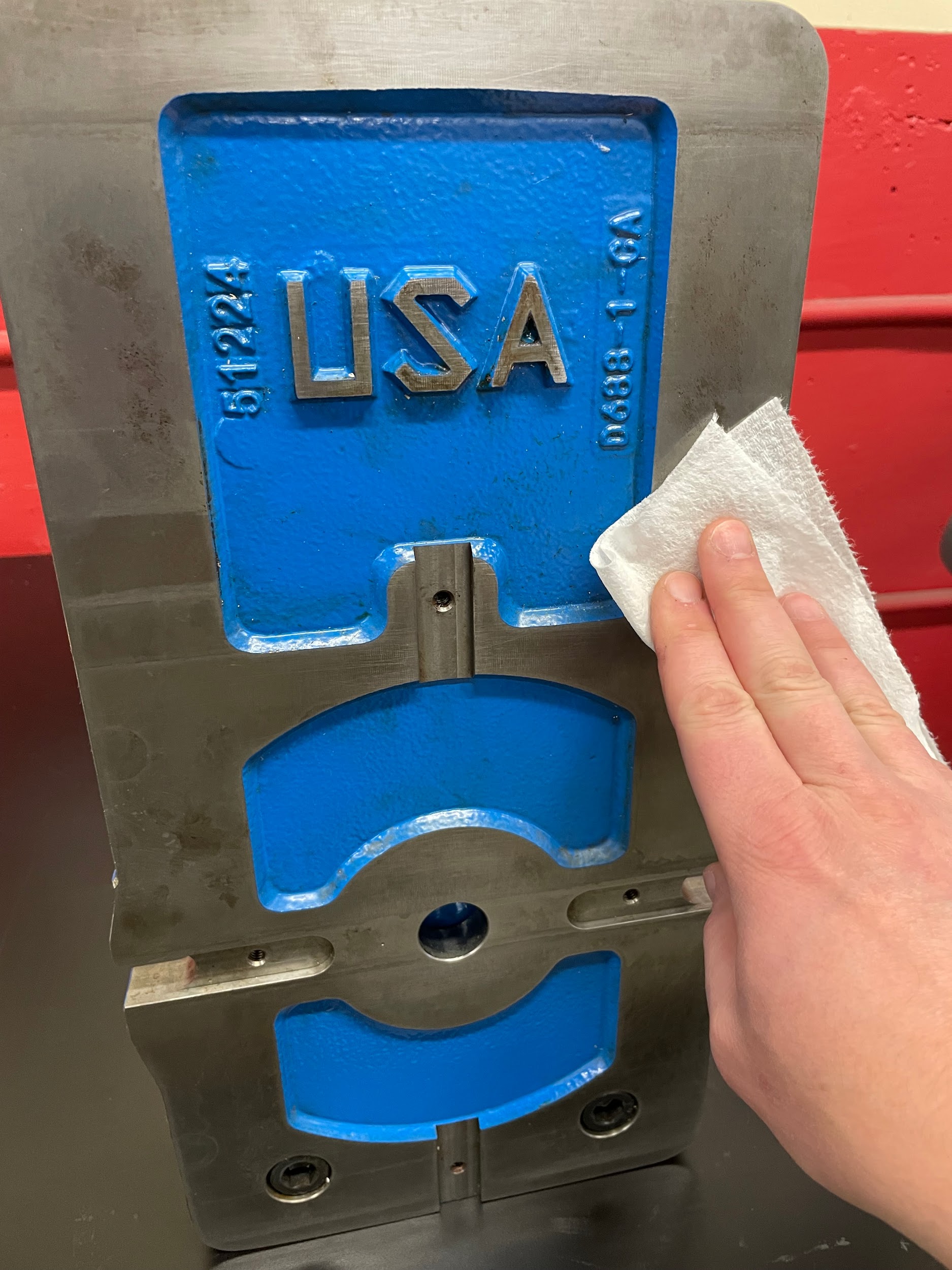
- Clean the top of the vise of all chips, debris, and oil.
- Open the vise wide enough to easily reach the bolts holding the jaw plates in place. Sometimes this may be all the way open.
- Select the proper hex key for the retaining bolts.
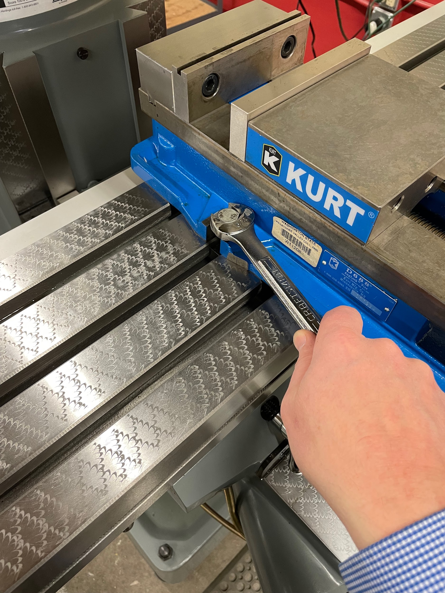
- Loosen and remove the four socket head cap screws.
- Remove the jaw plates.
- Clean and inspect the area under the plates. Pay particular attention to the area under and in front of the solid jaw plate. This area can be easily damaged because one of the parallels is always in this position. If operators are not careful, chips can get under the parallels and damage this area the most. While the jaw plate is off, this area can be lightly honed if the damage is burred up, causing parallels to not sit flat.
- Clean out the threaded holes where the new jaw plates are to be mounted. The holes on the back of the solid jaw can get especially dirty and will need to be properly cleaned of chips and dried oil to prevent damage to the threads.
- Clean the new jaw plates that are to be mounted on the jaws. Check for damage and burrs on the surface that will come into contact with the top of the base.
- Put the jaw plates in place. If using a Kurt vise, be aware that the jaw plate with the slot in it is for the vise stop and is intended for use on the solid jaw so that it will not move.
- Clean the heads and threads of the bolts.
- Install the bolts through the jaw plates and into the jaws. They should thread in easily with fingers; if they don’t, stop and check for cleanliness.
- Tighten bolts to the proper torque.
Step 6: Clean and inspect the area under the plates. Pay particular attention to the area under and in front of the solid jaw plate. This area can be easily damaged because one of the parallels is always in this position. If operators are not careful, chips can get under the parallels and damage this area the most. While the jaw plate is off, this area can be lightly honed if the damage is burred up, causing parallels to not sit flat.
Step 11: Install the bolts through the jaw plates and into the jaws. They should thread in easily with fingers; if they don’t, stop and check for cleanliness.
Step 11: Install the bolts through the jaw plates and into the jaws. They should thread in easily with fingers; if they don’t, stop and check for cleanliness.
Vise Squaring
Squaring a vise is one of the most important aspects of using a milling machine. This refers to the solid jaw of the vise being in line with the side to side table movement of the milling machine. This alignment process gives the operator the ability to machine features, or a series of holes, perpendicular or parallel to the side of the part that is put against the solid jaw. This is a big improvement to the layout and center punching required to get holes in alignment on the drill press.
If a vise is checked after use, and it is found to be out of square, it is preferable to completely remove the vise and clean under it instead of just loosening and altering its position. This is because the operator could accidentally introduce chips or dried oil underneath the vise if adjusting rather than cleaning.
Step by step process for squaring the milling vise:
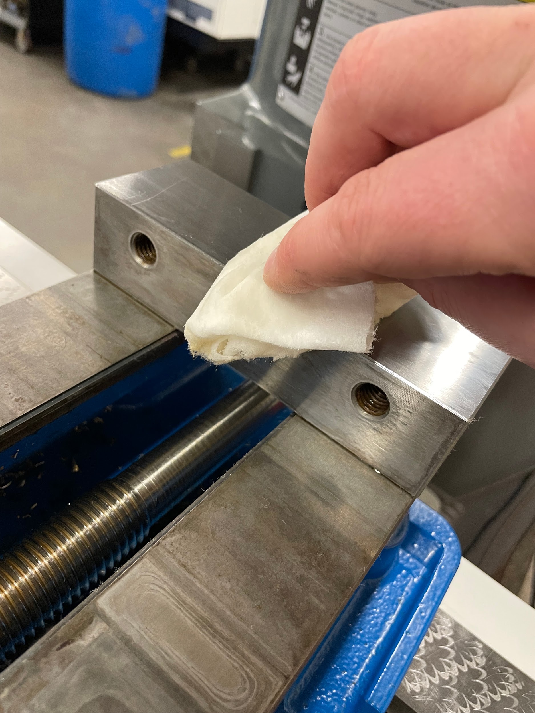
- Lift the vise and place on its side and clean the underneath with a rag to remove any chips or oil residue.
- Inspect the bottom of the vise for damage.
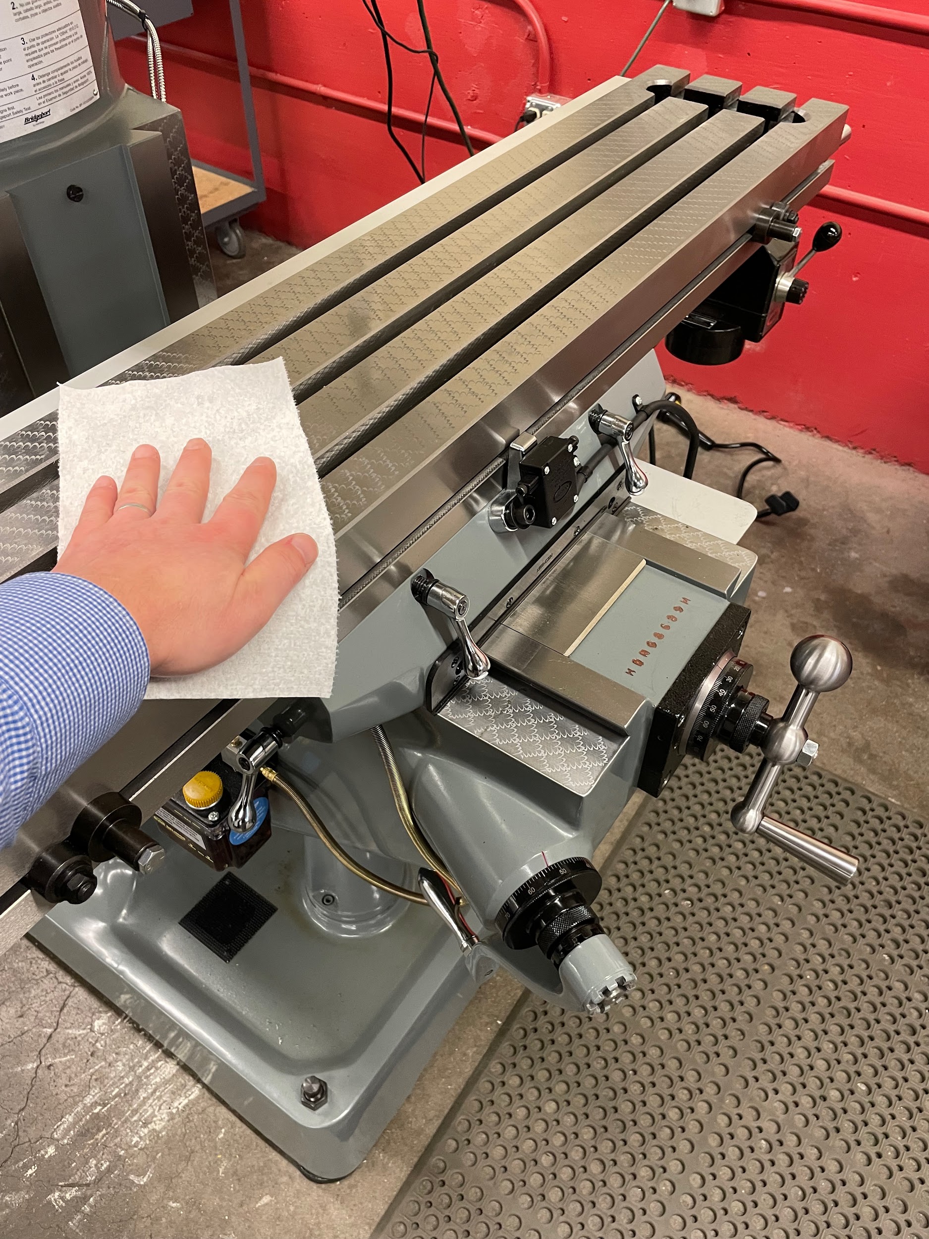
- Clean the table with a rag to remove any chips or oil residue.
- Inspect the table for damage.
- If any damage is found on the table or vise that is burred up from the surface, it can be gently honed flat. Make sure to run the hone over the entire surface to avoid altering just one spot. Reclean the surfaces after any honing.
- Wipe both the table and bottom of the vise with a clean hand to remove any impurities the rag may have left behind.
- Lift the vise, gently set the center of the base on the corner of the table, and lever it onto the top surface. This is to avoid any damage that directly putting the vise onto the surface might do.
- Position the vise in the center of the table with the hold down points above the center tee slot.
- Clean the hold down bolts and tee nuts.
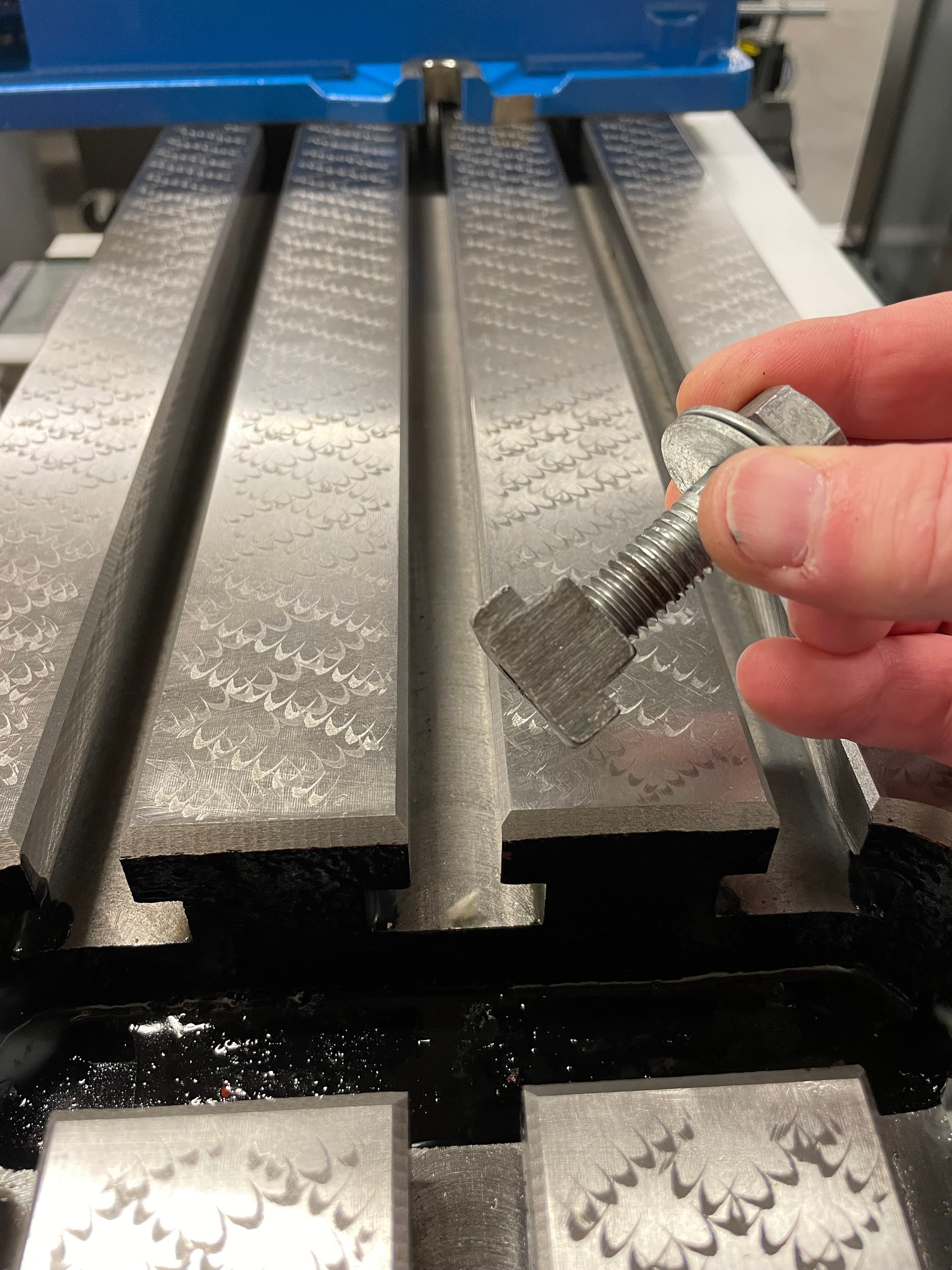
- Install the tee nuts and bolts into the tee slots and onto the vise.
- Tighten by hand and loosen a quarter turn.
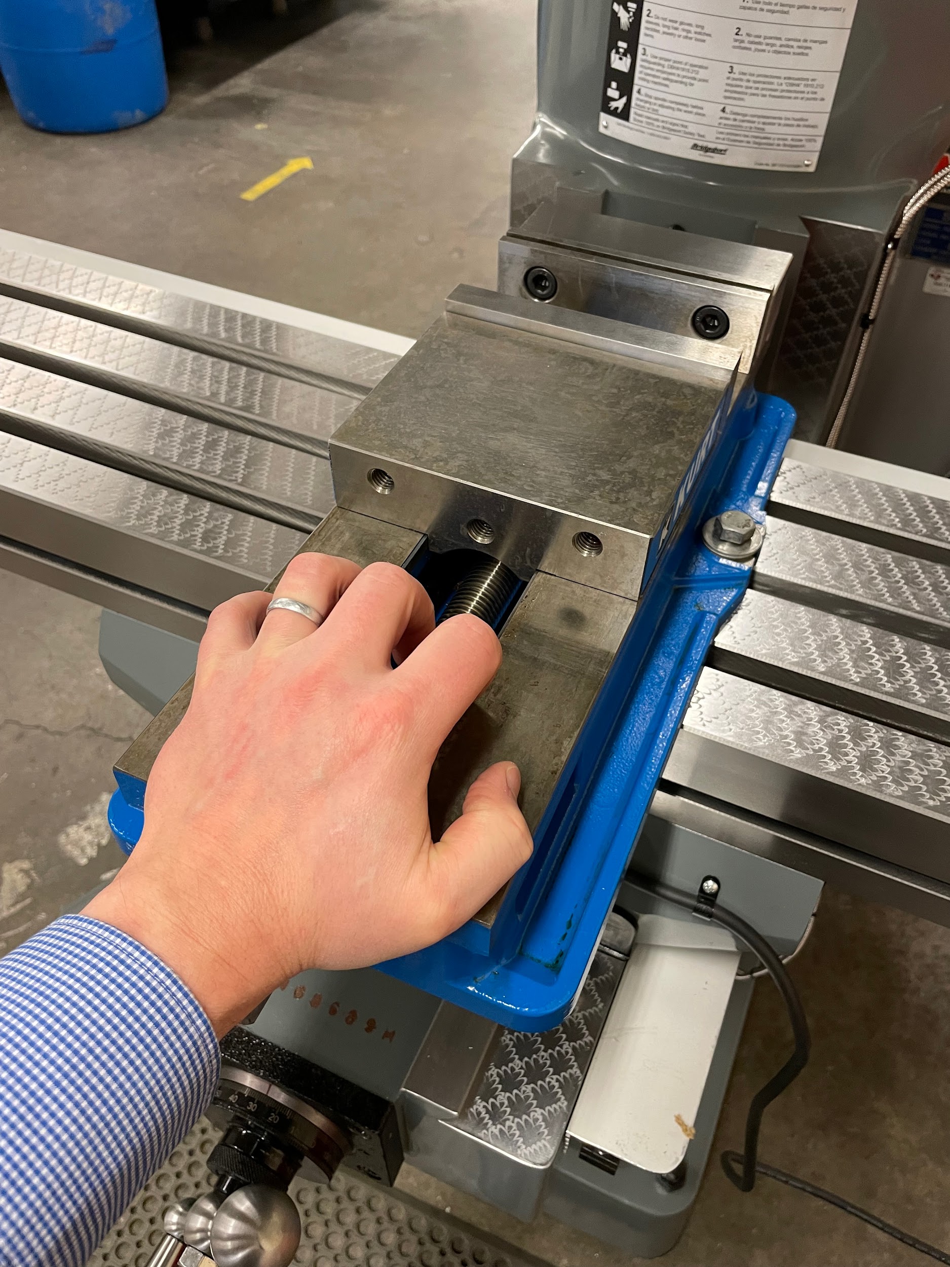
- Push the vise towards the back of the machine, tight against the bolts and tee slots. This action will roughly align the vise and make the precision alignment easier because the vise will be closer to the correct position.
- Tighten the bolts.
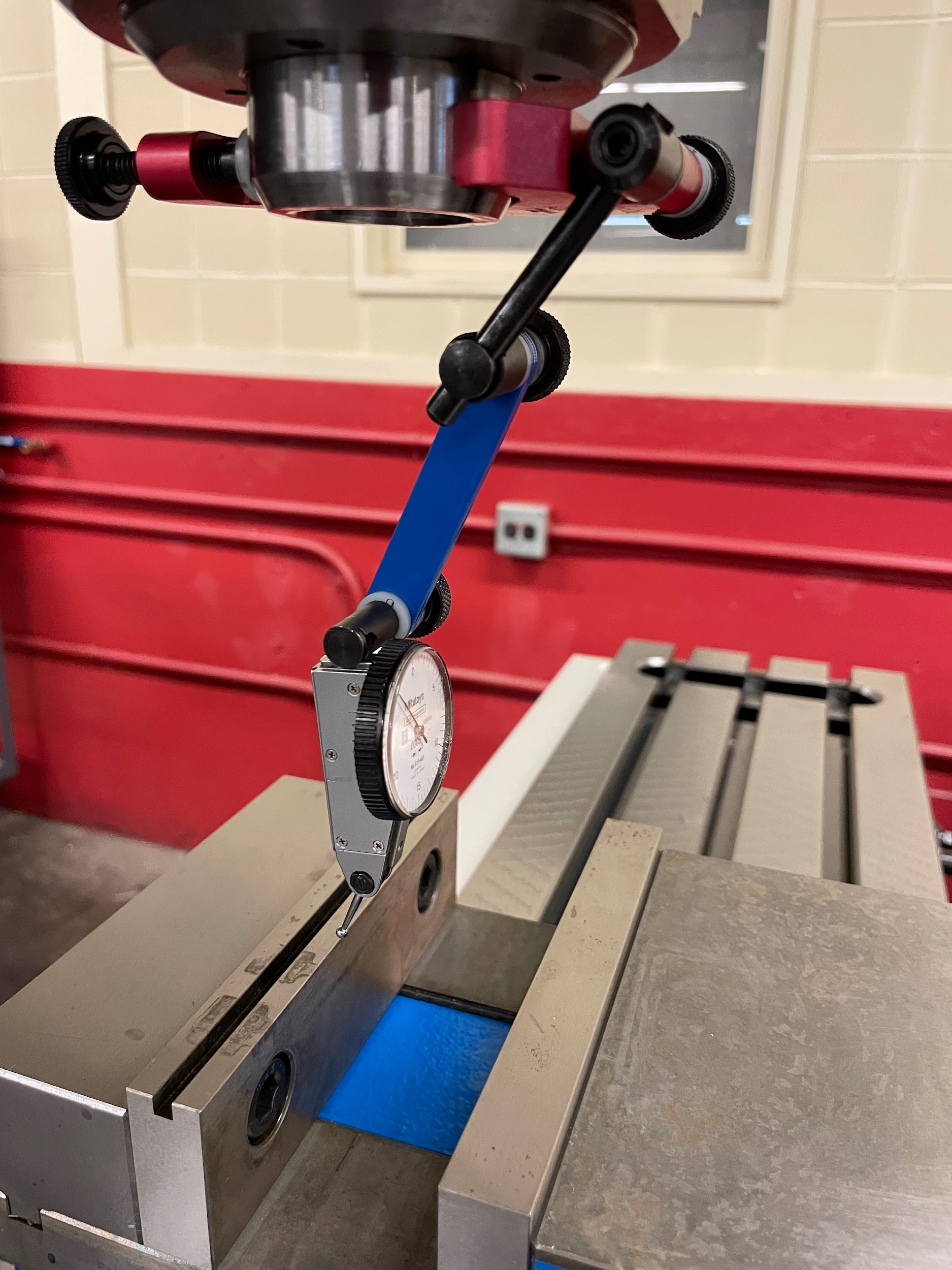
- Install a test indicator into or onto the spindle nose.
- Bring the stylus of the indicator up to touch one side of the solid jaw plate face.
- Move the saddle to load the indicator about .010.
- Zero the indicator.
- Move the table so that the indicator tip is at the other end of the solid jaw.
- Look at the indicator and the difference between the first side and the second side. Notice which of the two sides is the lowest and position the indicator on that side.
- Loosen the bolt on the side the indicator is on.
- Tap the vise to increase the reading of the indicator to match the position on the other side. Since the position of the pivot point is outside both of the measurement points, both the point the indicator is on and the other point will change. The side the indicator is on will change by a larger amount because it is further away from the pivot point.
- Retighten the bolt.
- Recheck the vise for square. If the indicator measures more than .0005 over the 6″ vise jaw, keep performing the squaring procedure.
“Step 1: Lift the vise on end on a bench and clean the underneath side with a rag to remove any chips or oil residue.”
“Step 3: Clean the table with a rag to remove any chips or oil residue.”
“Step 10: Install the tee nuts and bolts into the tee slots and onto the vise. ”
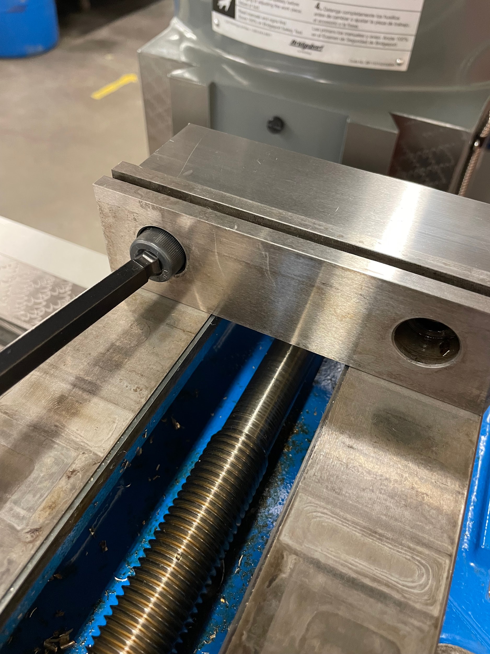
“Step 12: Push the vise towards the back of the machine, tight against the bolts and tee slots. This action will roughly align the vise and make the precision alignment easier because the vise will be closer to the correct position.”
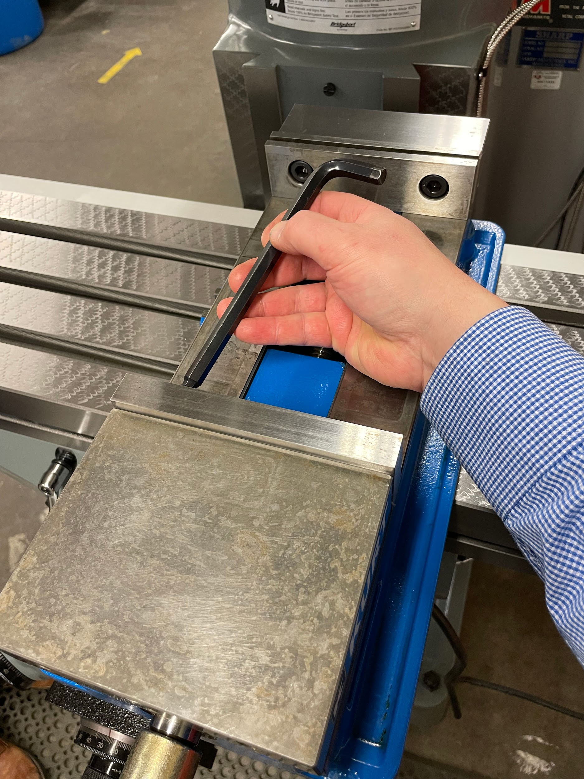
“Step 13: Tighten the bolts.”
“Step 14: Install a test indicator into or onto the spindle nose.”
“Step 14: Install a test indicator into or onto the spindle nose.”
“Step 14: Install a test indicator into or onto the spindle nose.”
“Step 14: Install a test indicator into or onto the spindle nose.”
“Step 18: Move the table so that the indicator tip is at the other end of the solid jaw. ”

“Step 23: Recheck the vise for square. If the indicator measures more than .0005 over the 6″ vise jaw, keep performing the squaring procedure.”

“Step 23: Recheck the vise for square. If the indicator measures more than .0005 over the 6″ vise jaw, keep performing the squaring procedure.”

Author’s Tip
In theory, once a vise is squared, it will remain square. However, you can never trust that the person using the machine before you did the squaring process correctly, or that it hasn’t somehow been knocked out of alignment. For that reason, quickly check the vise before starting work on anything important. Once you have done it a few times, the checking process only takes a couple minutes, but it can save you tons of heartache and scrapped parts if you find it’s not square at the end of a run of parts.
Seating The Work Against Parallels
Seating a part against parallels is an important aspect of work setup. Essentially, what the machinist is doing as they are seating the part against parallels is reducing any potential available space that might exist between the part and the parallels, or the parallels and the vise. The standard way this is performed is to tap the part down towards the vise with a dead blow hammer. It is important to note that if the sides of the part aren’t square, it may not seat against both parallels.
Step by step process for seating the work against parallels:
- Clean the top of the vise thoroughly.
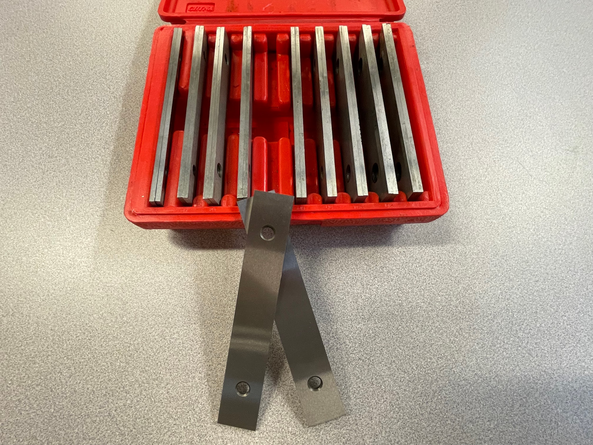
- Select and clean a suitable pair of parallels. The parallels selected for a job should provide no more than ⅛” of extra material above the jaw plates. Extra material would be defined as material that isn’t involved in an external cutting operation. For example, if the machinist is to cut a ¼” deep step all the way around a part, when setup, the part should have no more than ⅜” above the jaw plates. This ensures there is the maximum holding grip on the part, and enough surface in contact with the solid jaw to create square intersections between surfaces.
- Inspect both the parallels and the top of the vise where the parallels will sit for damage or embedded chips.
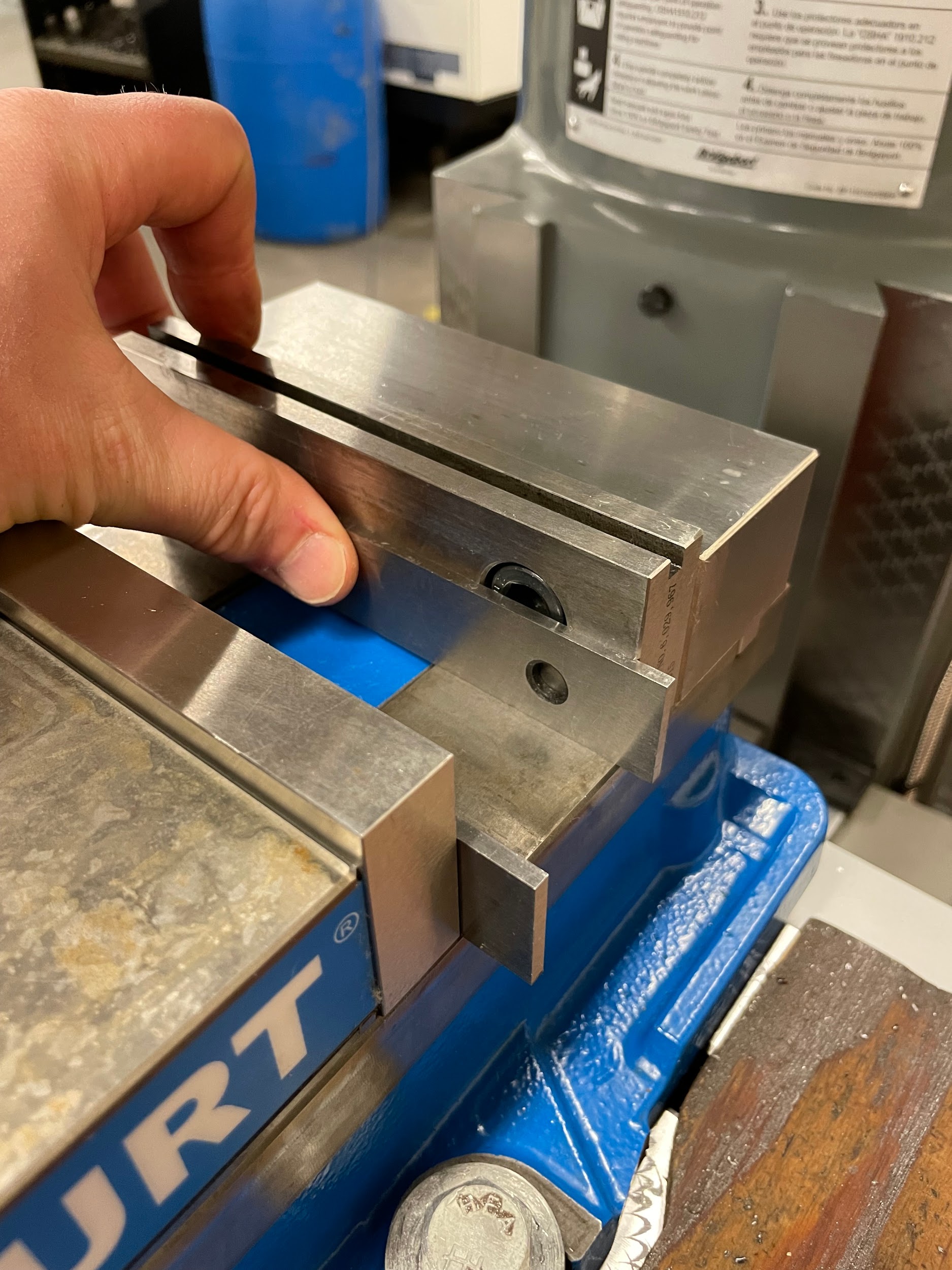
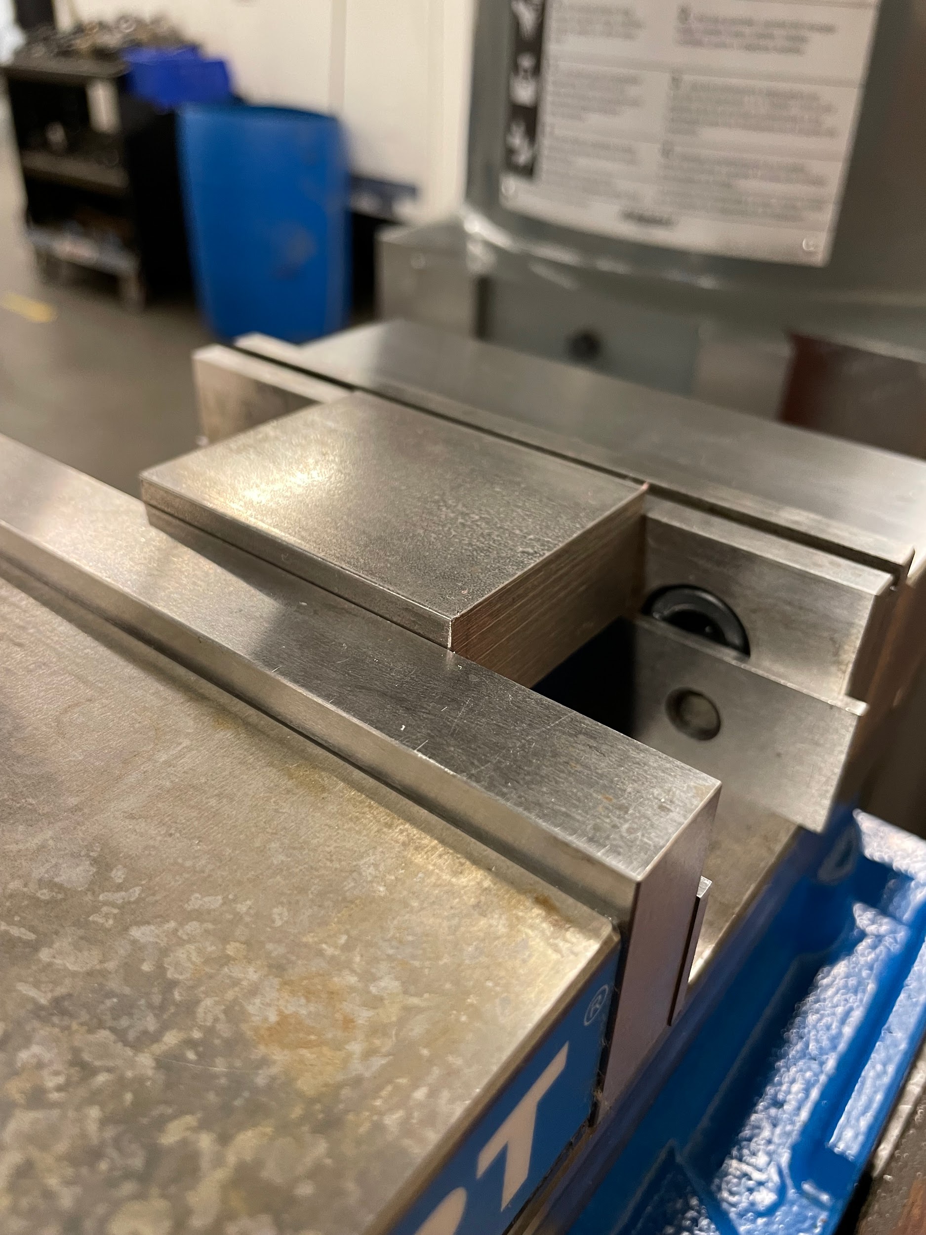
- Place the parallels in the vise against the jaw plates.
- Close the vise so that the gap is about ⅛” larger than the part.
- Deburr and clean the part of any chips, oil, or contaminants.
- Put the part on top of the parallels in the center of the vise.
- Tighten the vise with the right hand while pushing down on the part with the left hand.
- With the dominant hand, tap the part straight down and toward the top of the vise, with a dead blow hammer.
- With the non-dominant hand, gently grip a parallel with fingers and slide it in and out of the vise.
- Repeat the tapping and sliding until the parallels become snug.
“Step 4: Place the parallels in the vise against the jaw plates.”
“Step 7: Put the part on top of the parallels in the center of the vise.”
“Step 8: Tighten the vise with the right hand while pushing down on the part with the left hand.”
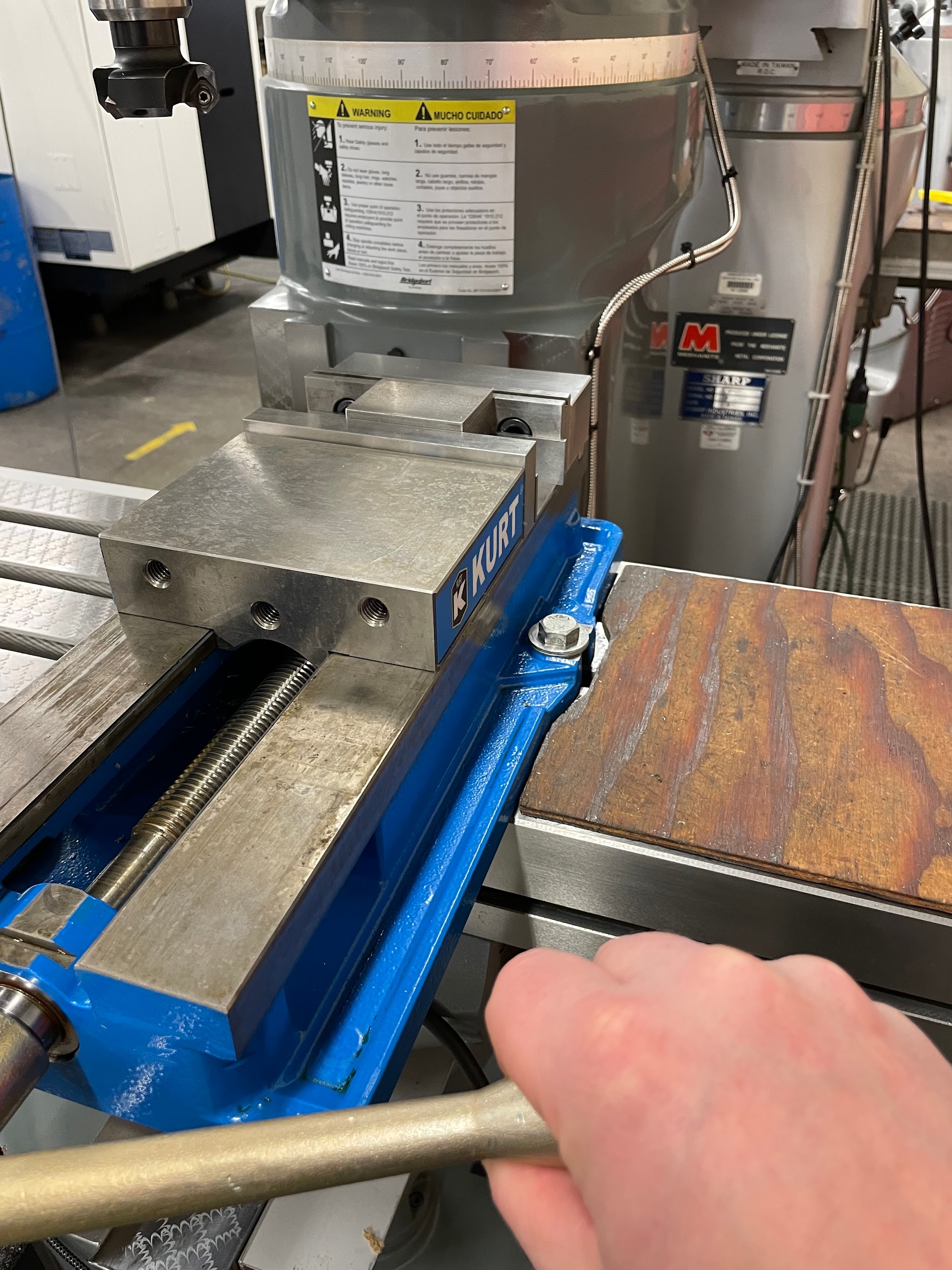
“Step 9: With the dominant hand, tap the part straight down and toward the top of the vise, with a dead blow hammer.”
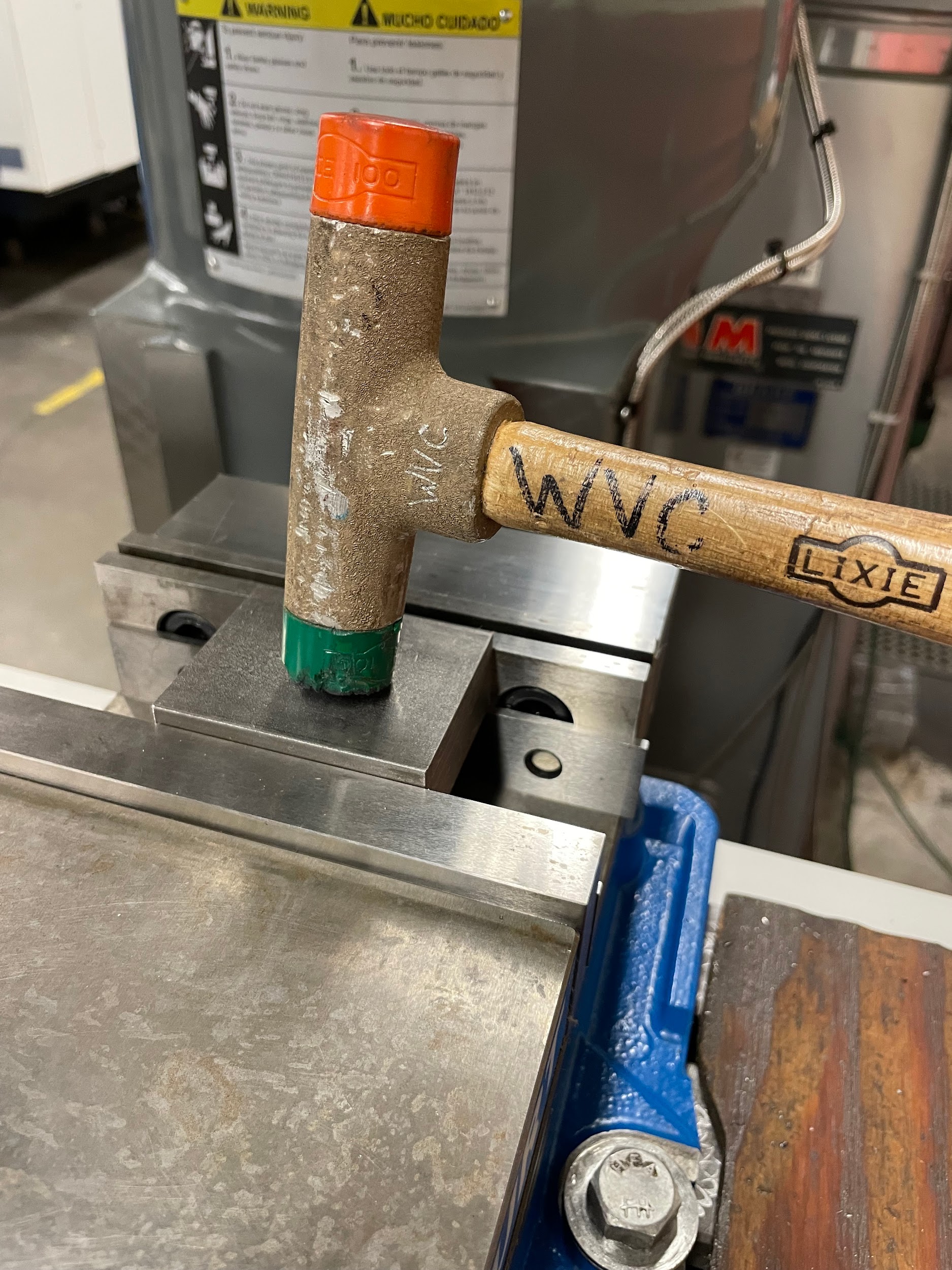
“Step 9-11: With the dominant hand, tap the part straight down and toward the top of the vise with a dead blow hammer. With the non-dominant hand, gently grip a parallel with fingers and slide it in and out of the vise. Repeat the tapping and sliding until the parallels become snug.”

Author’s Tip
When I am seating parallels, after the cleaning process, I like to set the parallels against the jaw plates and slide them back and forth over the top of the vise. If there is any potential unseen debris that may be on the parallels, it has an opportunity to be pushed out of the vise by this motion. Also, if there is any damage to the vise/parallel mating surfaces, it will show itself as a slight clicking noise as the parallels are slid along the jaw plate. When I hear this, it lets me know of potential damage to the parallel or vise that needs attention.
Edge Finding
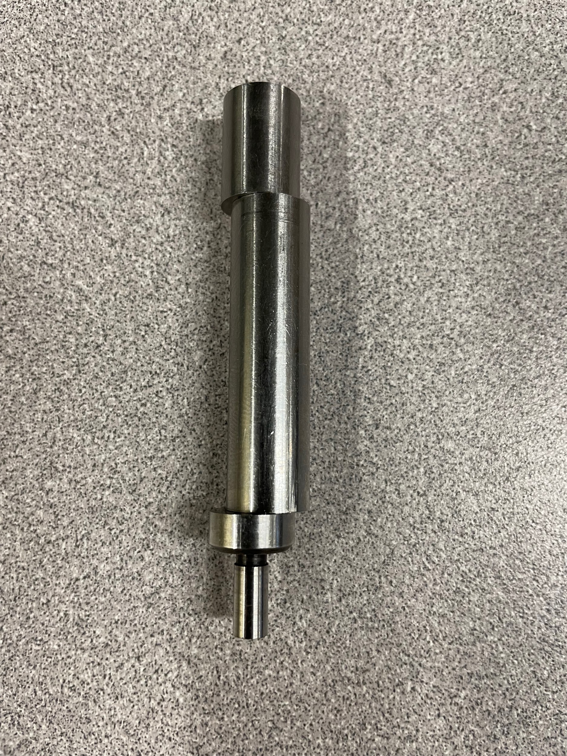
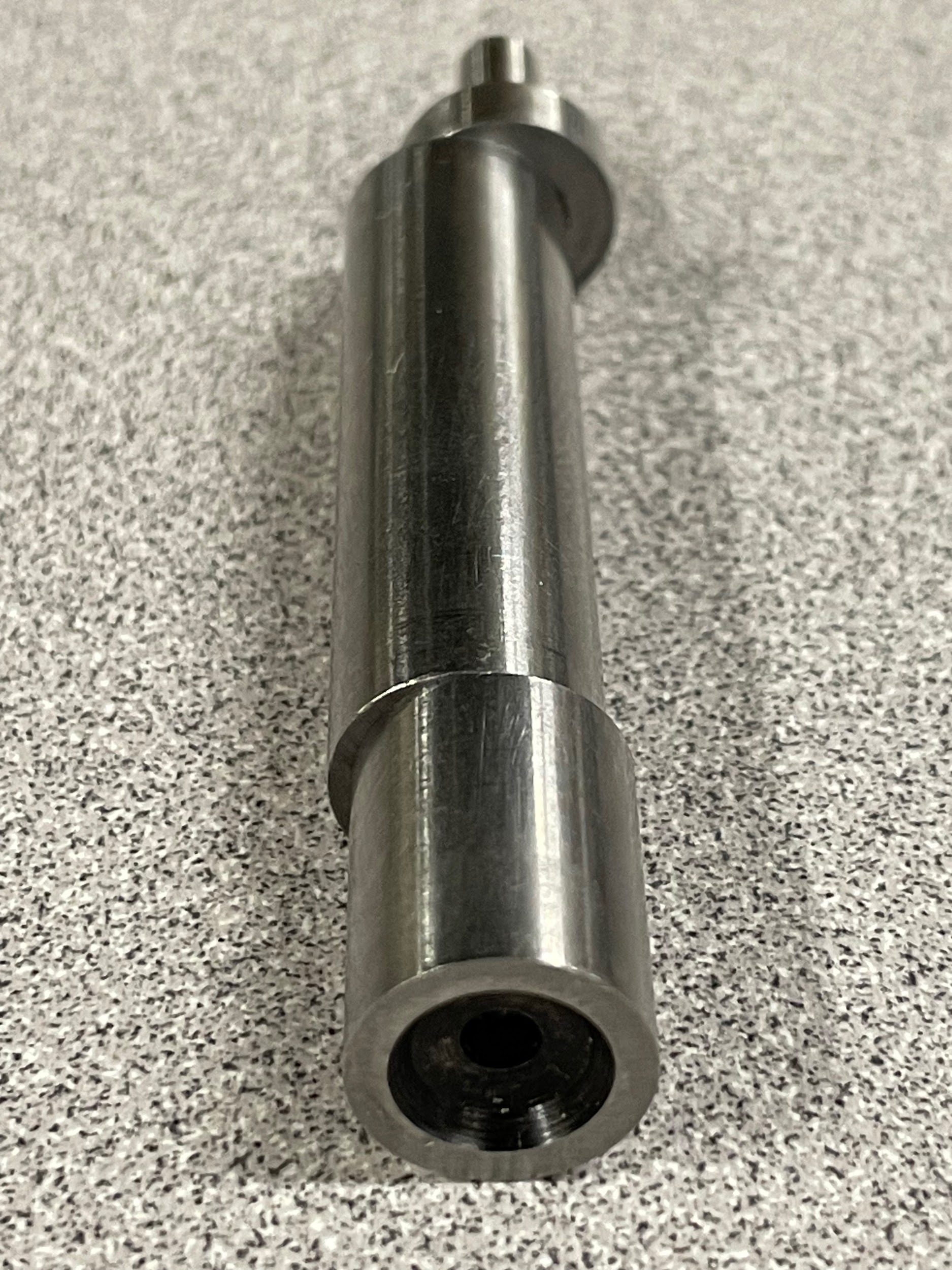
Edge finding is the process of identifying the edge of a part as a reference in order to create a feature at a specified position away from it. Edge finding is often done with a device called an edge finder. The edge finder is a tool that has a precise diameter for chucking purposes and a precise end that is used as an alignment device. Once the operator aligns the edge of the part with the edge finder, the center of the spindle is half the diameter of the edge finder tip away. Edge finding is an entry level skill that will allow the machinist to precisely position features with regard to datums. Datums are discussed in Chapter 3. If done properly, with a quality edge finder, accuracy within a couple thousandths of an inch is achievable.
Step by step process for edge finding:
- Load an edge finder into the spindle. This can be done in a solid holder, a collet, or a drill chuck. Make sure to grip the body and not the spring loaded tip.
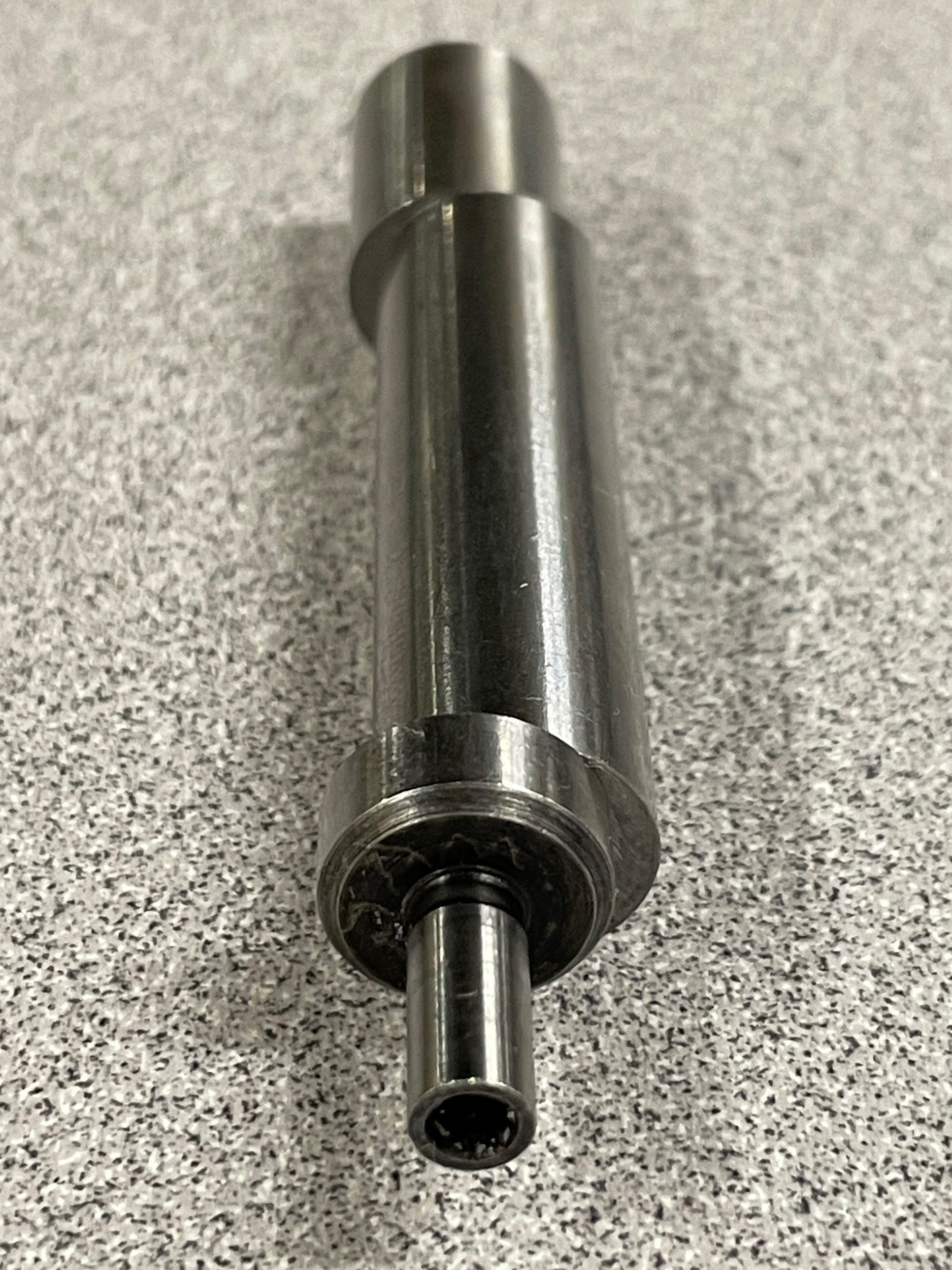
- With the spindle off, move the spring-loaded end of the edge finder to one extreme side so that the end and the body are not concentric.
- Select high gear.
- Turn the spindle on and adjust the speed handle until the machine is at 1000 RPM. This speed is the recommended RPM to edge find a part based on the manufacturer’s information.
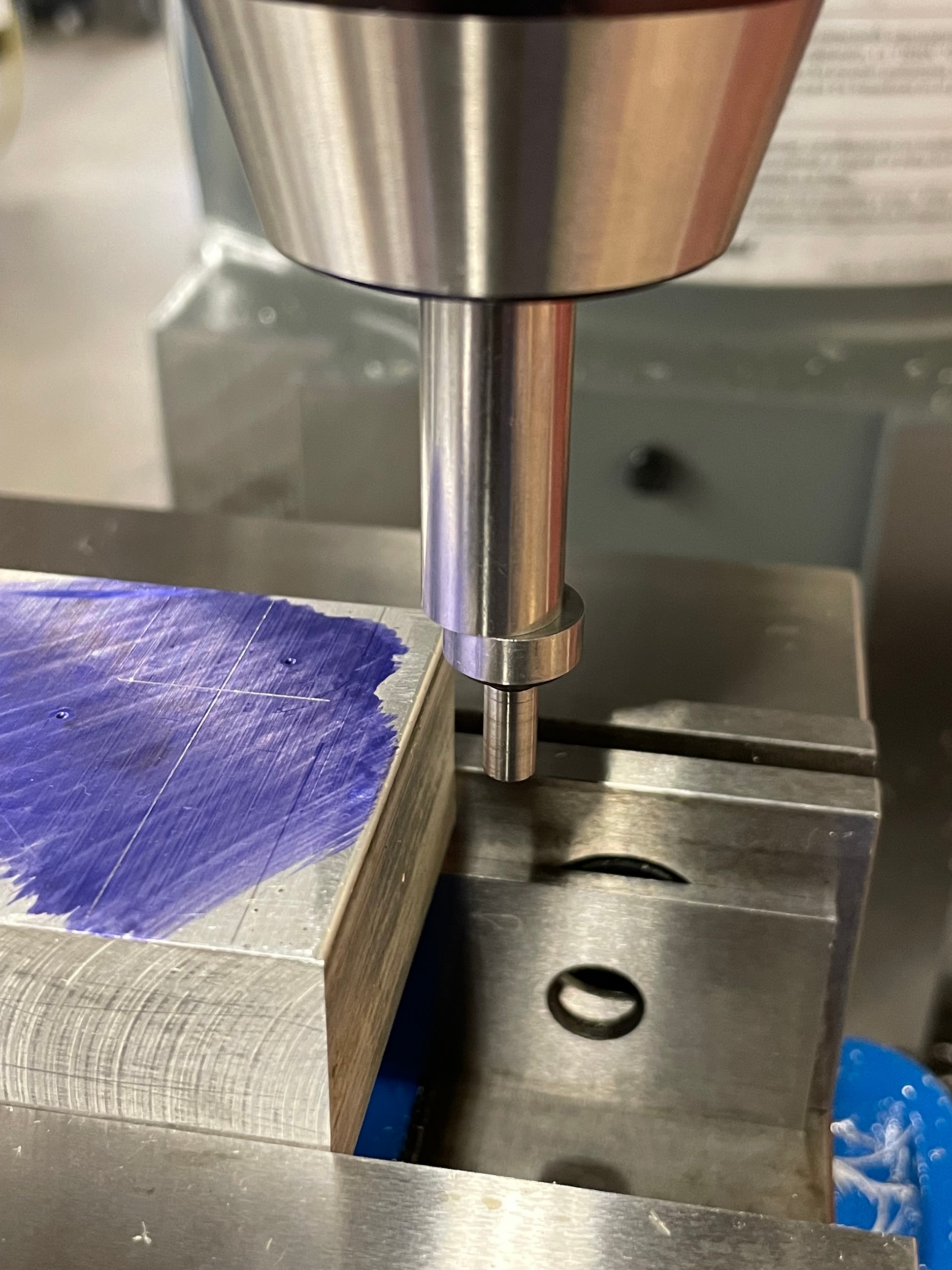
- Using the table, saddle, and knee handles, adjust the machine to where the edge finder is to the side and below the edge by at least 1/16″.
- Slowly move the edge finder into the work and watch the end become more and more concentric with the body until the end of the edge finder pops at a right angle to the edge and is visibly non-concentric.
- Turn off the spindle.
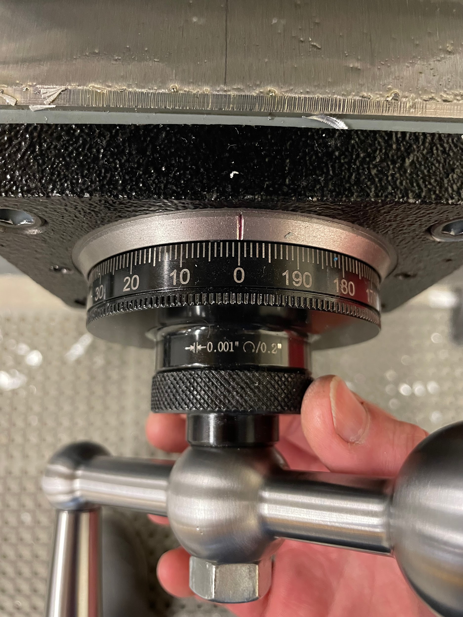
- Zero the graduated collar of the hand wheel that was moved.
- Raise the quill or lower the table so the edge finder will clear the work.
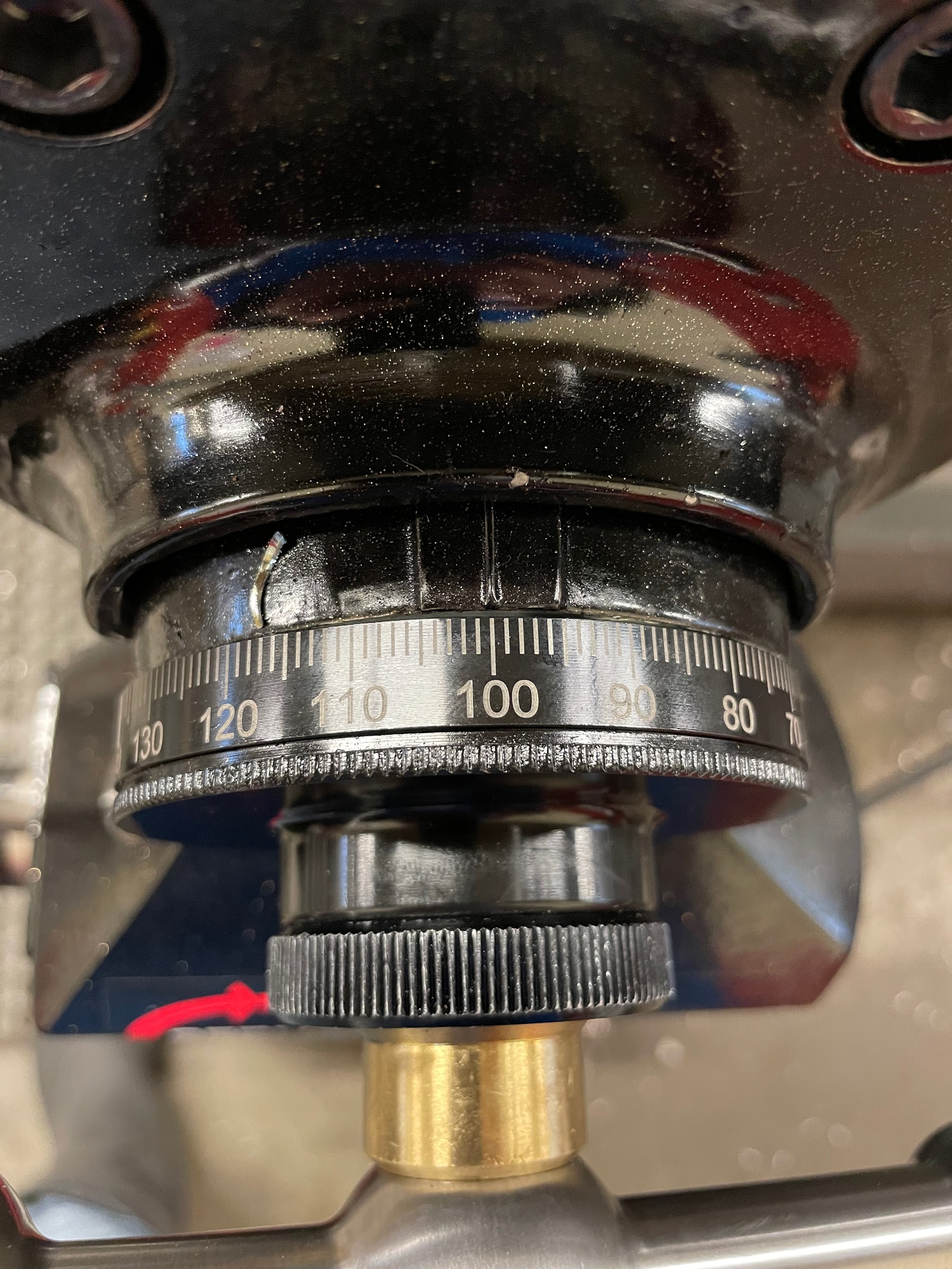
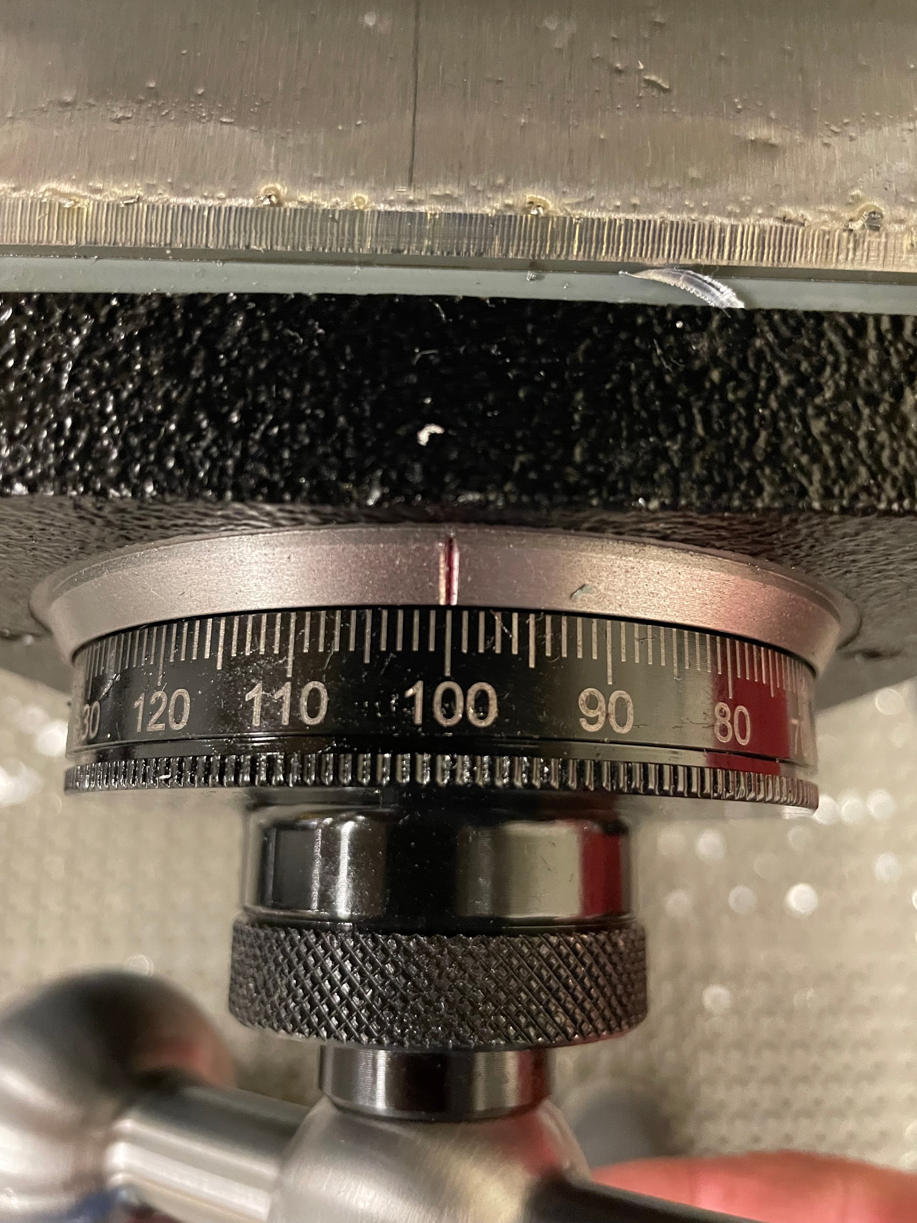
- Move the hand wheel by the radius of the end of the edge finder, and zero the graduated collar again.
- By hand, center the end of the edge finder with the body.
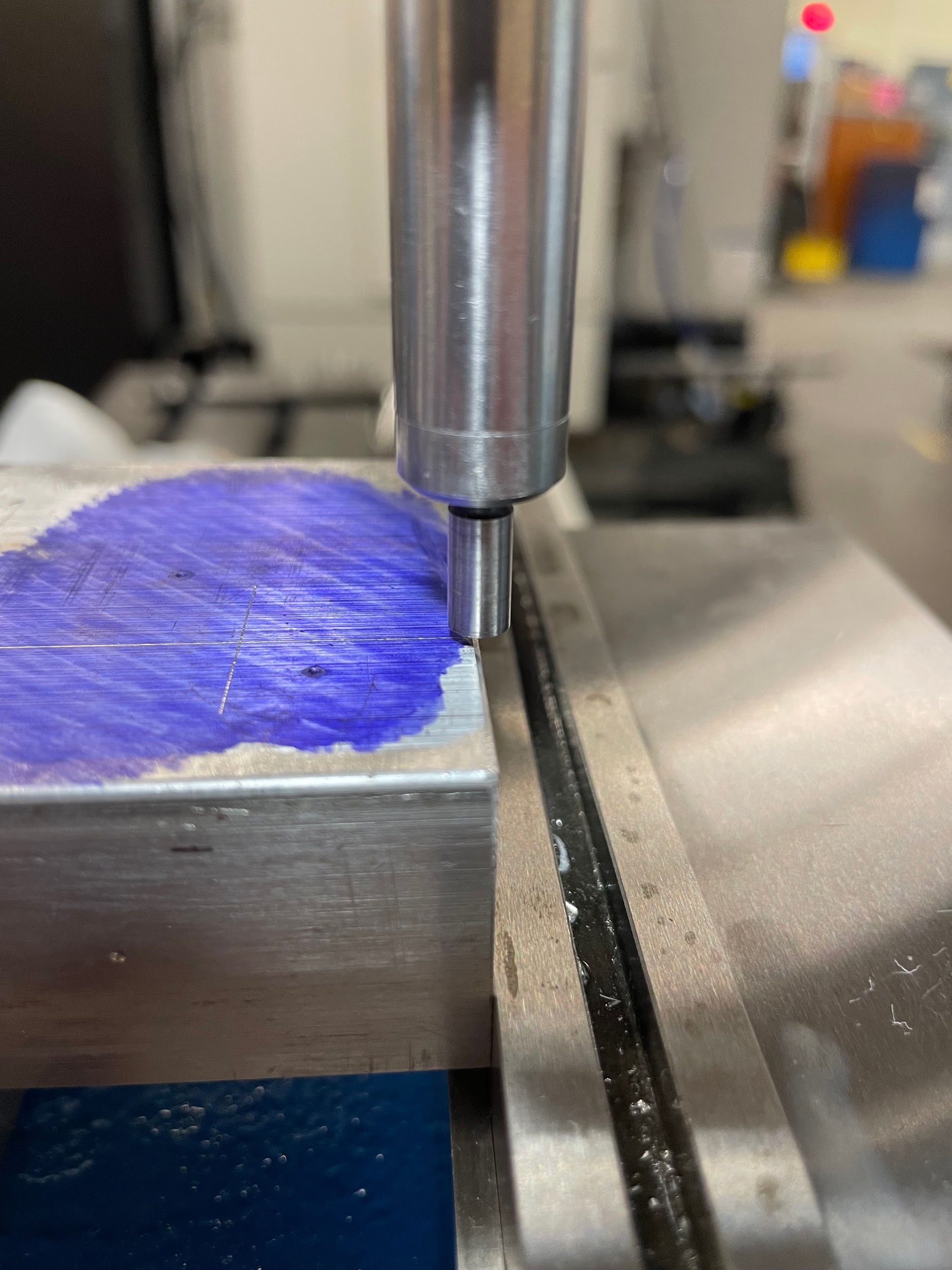
- Check that the edge of the work looks to be directly underneath the center of the edge finder.
- Repeat this process for the other edge of a square part.
- After completion, a corner of the part is set, and can serve as a reference for positioning other features.
“Step 2: With the spindle off, move the spring-loaded end of the edge finder to one extreme side so that the end and the body are not concentric.”
“Step 6: Slowly move the edge finder into the work and watch the end become more and more concentric with the body until the end of the edge finder pops at a right angle to the edge and is visibly non-concentric.”

“Step 8: Zero the graduated collar of the hand wheel that was moved.”
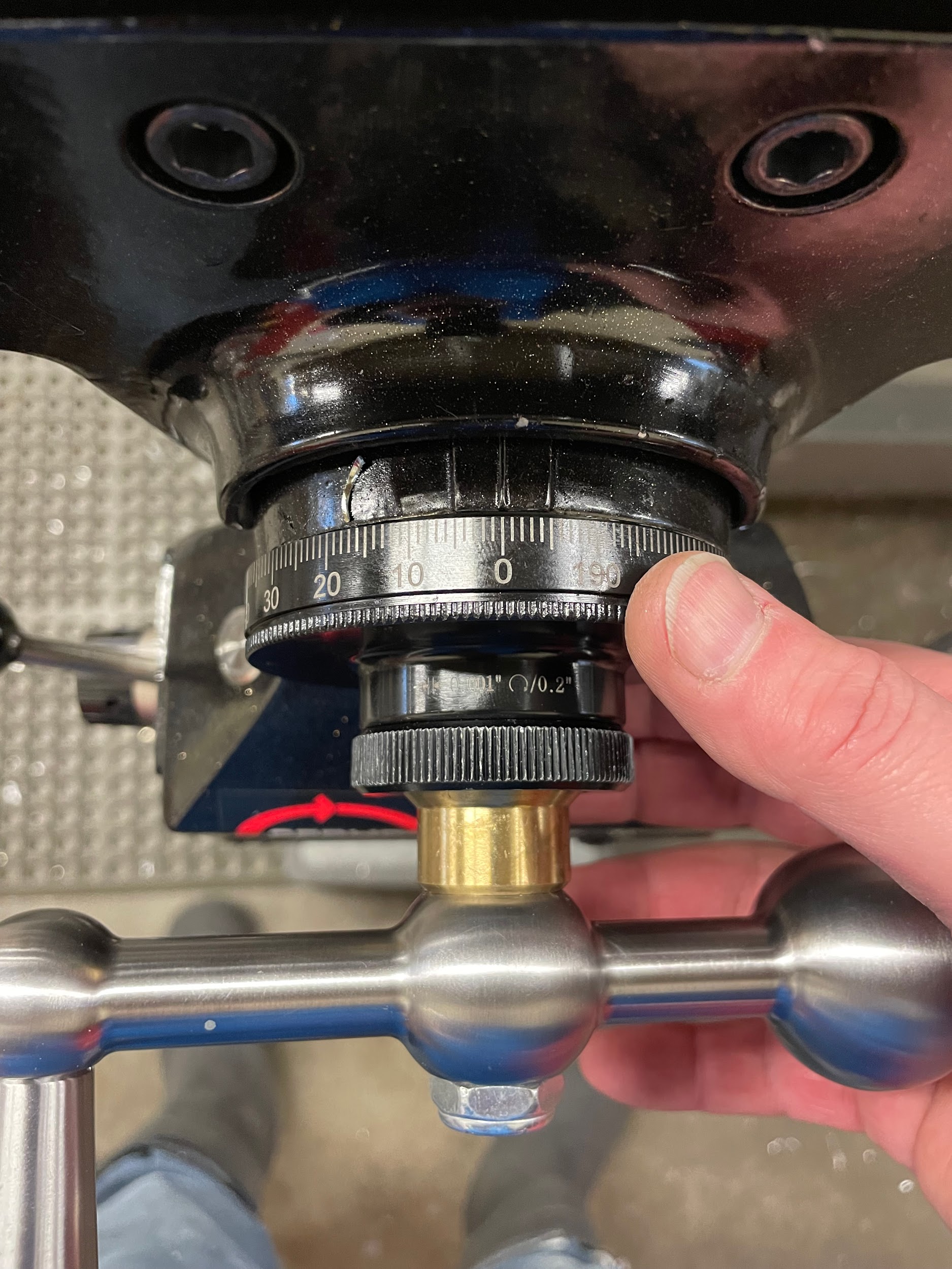
“Step 10: Move the hand wheel by the radius of the end of the edge finder, and zero the graduated collar again.”
“Step 12: Check that the edge of the work looks to be directly underneath the center of the edge finder.”
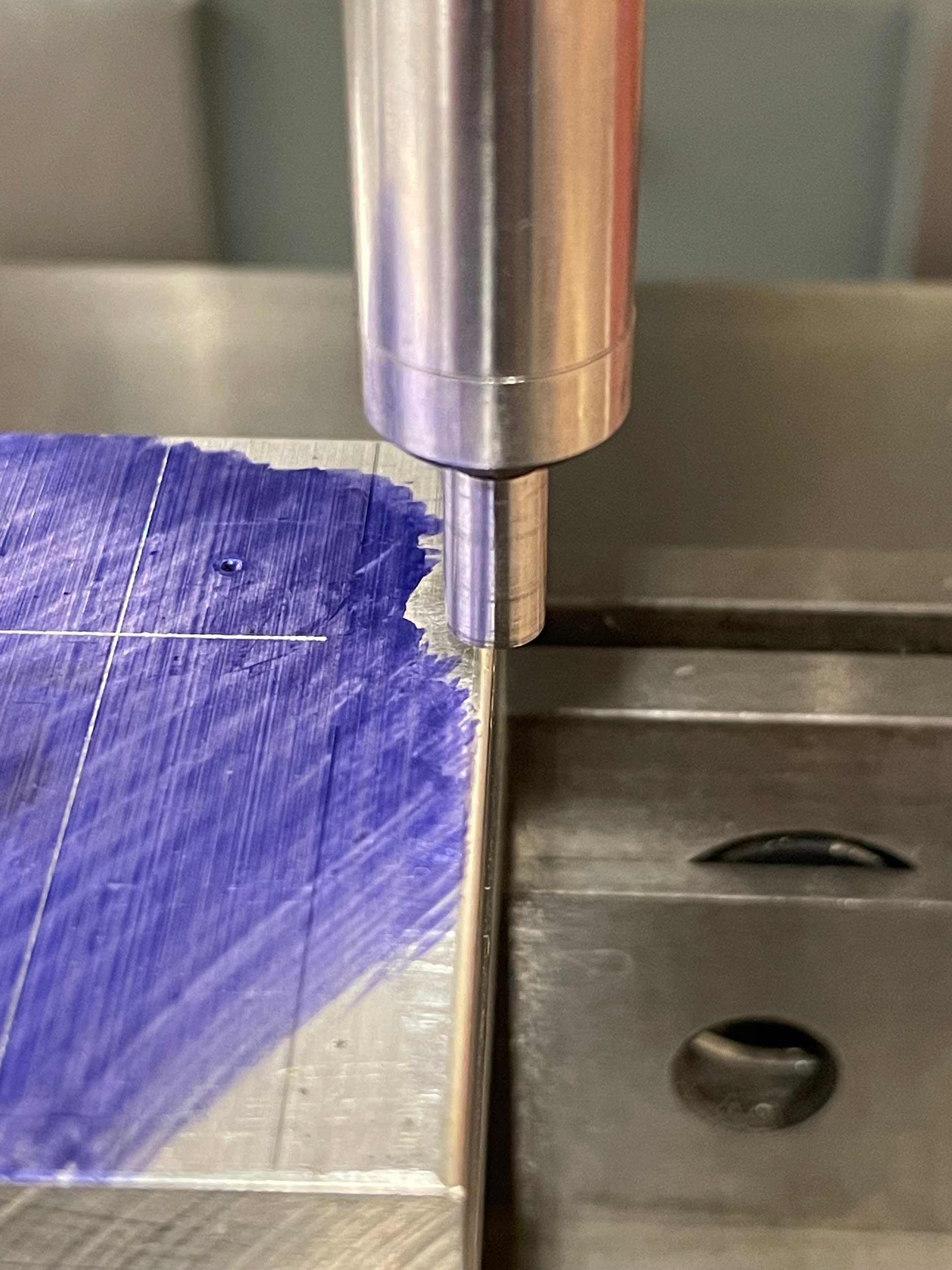
“Step 6: Slowly move the edge finder into the work and watch the end become more and more concentric with the body until the end of the edge finder pops at a right angle to the edge and is visibly non-concentric.”

“Step 8: Zero the graduated collar of the hand wheel that was moved.”
“Step 10: Move the hand wheel by the radius of the end of the edge finder, and zero the graduated collar again.”
“Step 12: Check that the edge of the work looks to be directly underneath the center of the edge finder.”
“Step 14: After completion, a corner of the part is set, and can serve as a reference for positioning other features.”
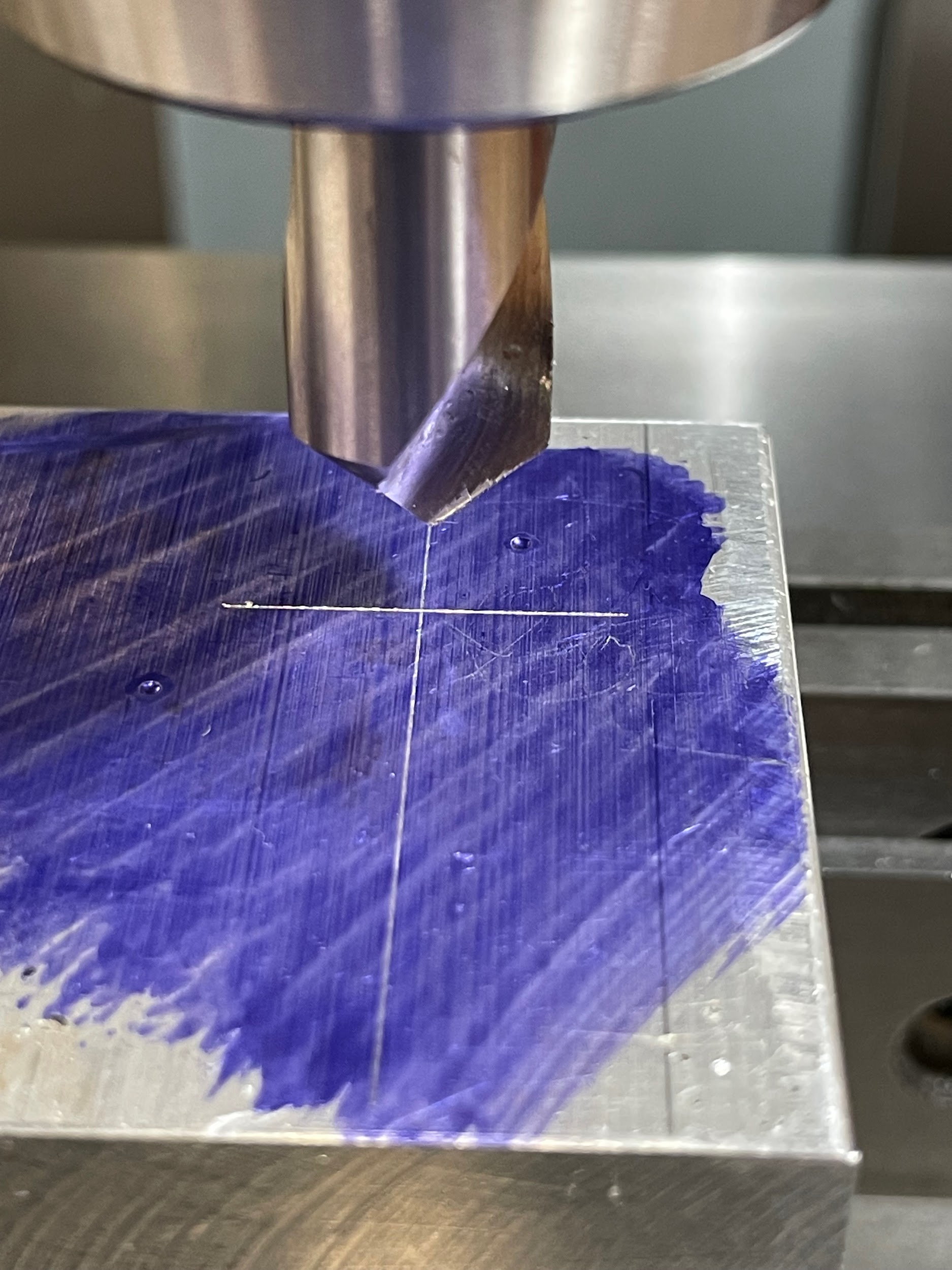
“Step 14: After completion, a corner of the part is set, and can serve as a reference for positioning other features.”

Finding Center
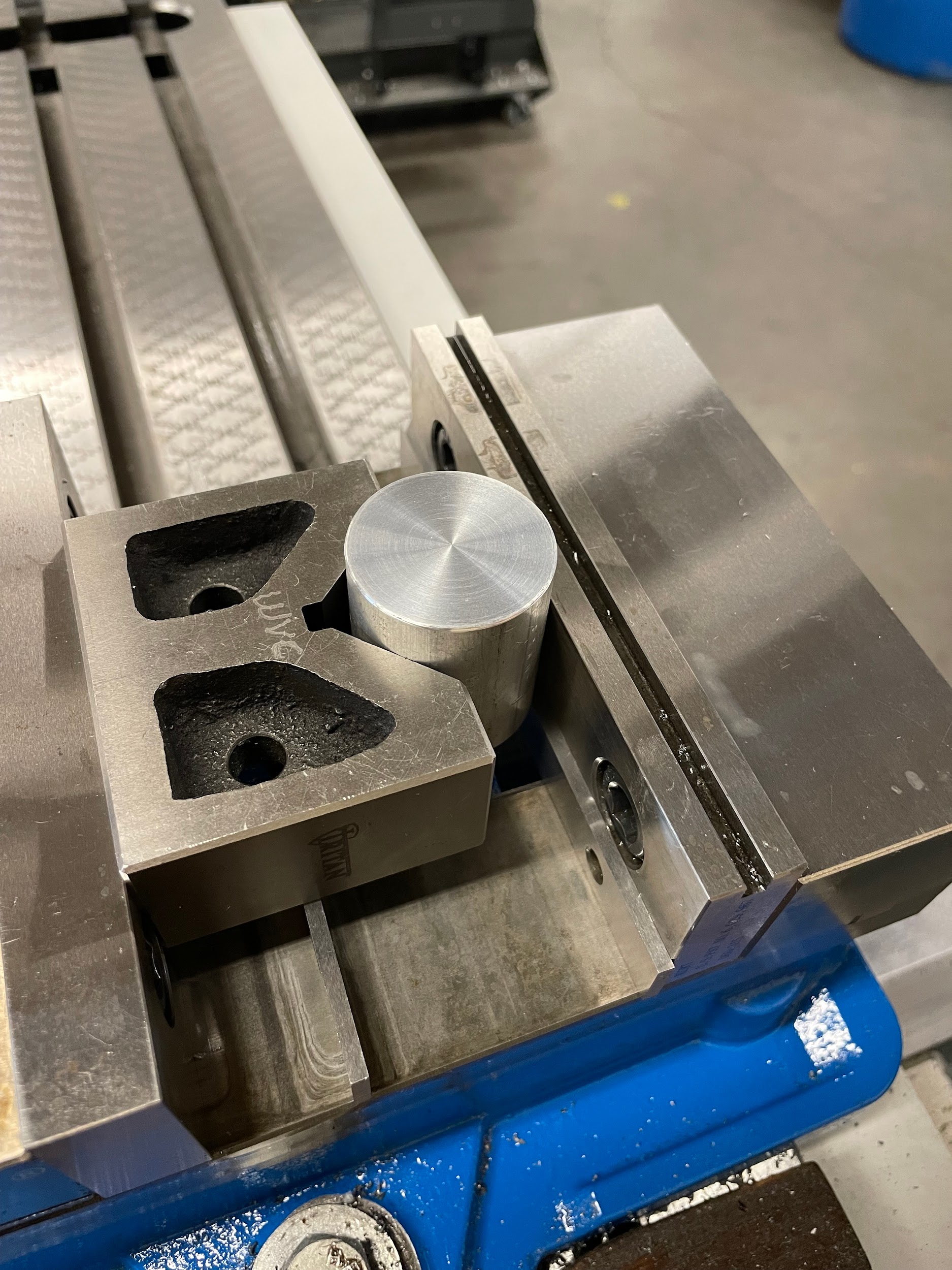
Finding the center of a part is as important as finding the edge of a part. Often, when round parts are machined on a milling machine, the center must be found, and a tool other than an edge finder needs to be used. Similarly, the operator may be asked to machine a part that had previous work done to it. The new work may need to be located off of existing features or holes. Finding the center of the holes or bores in the part may be necessary to set up the job.
Step by step process for finding center:
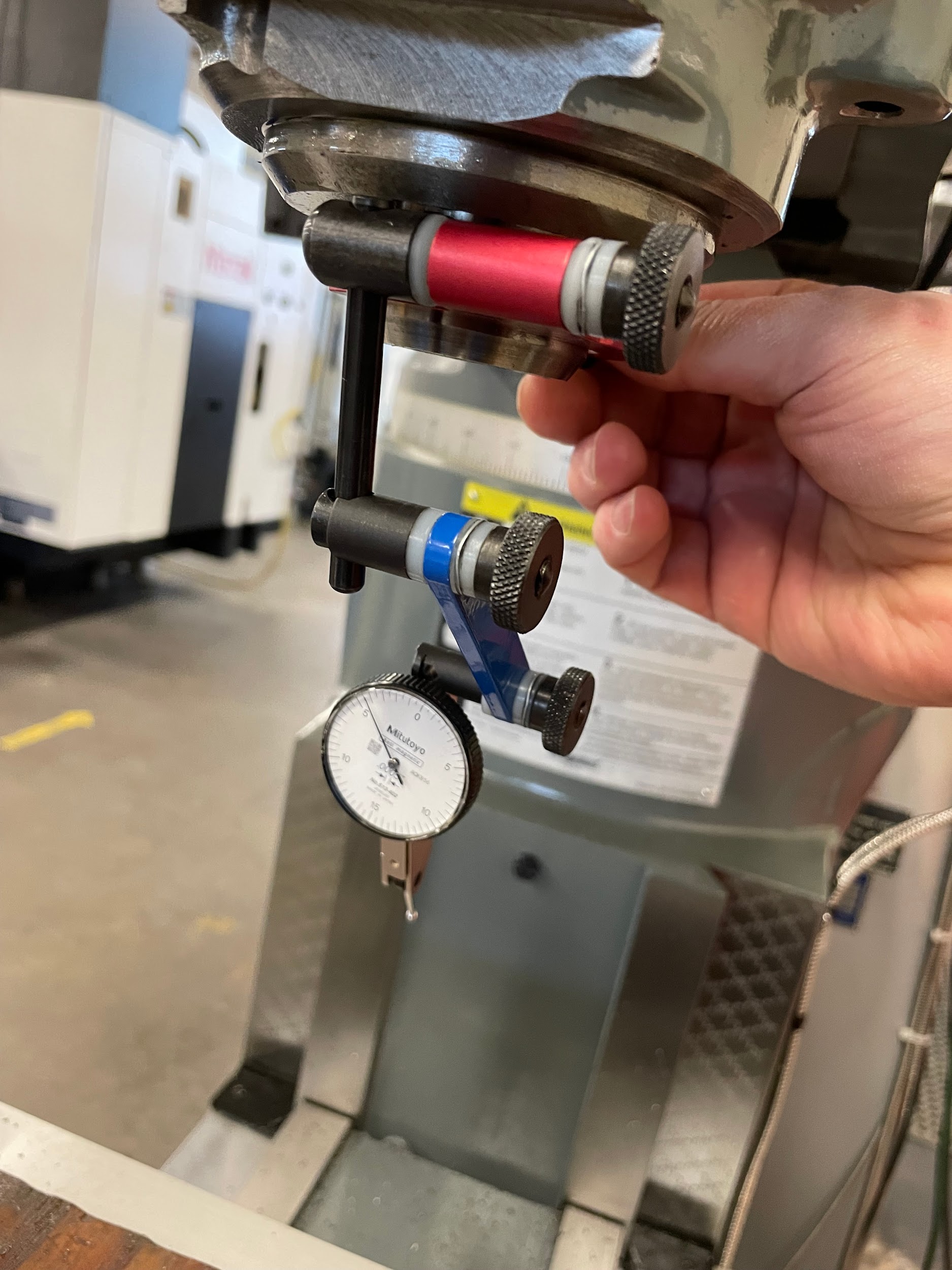
- Install an indicator holder into or onto the spindle.
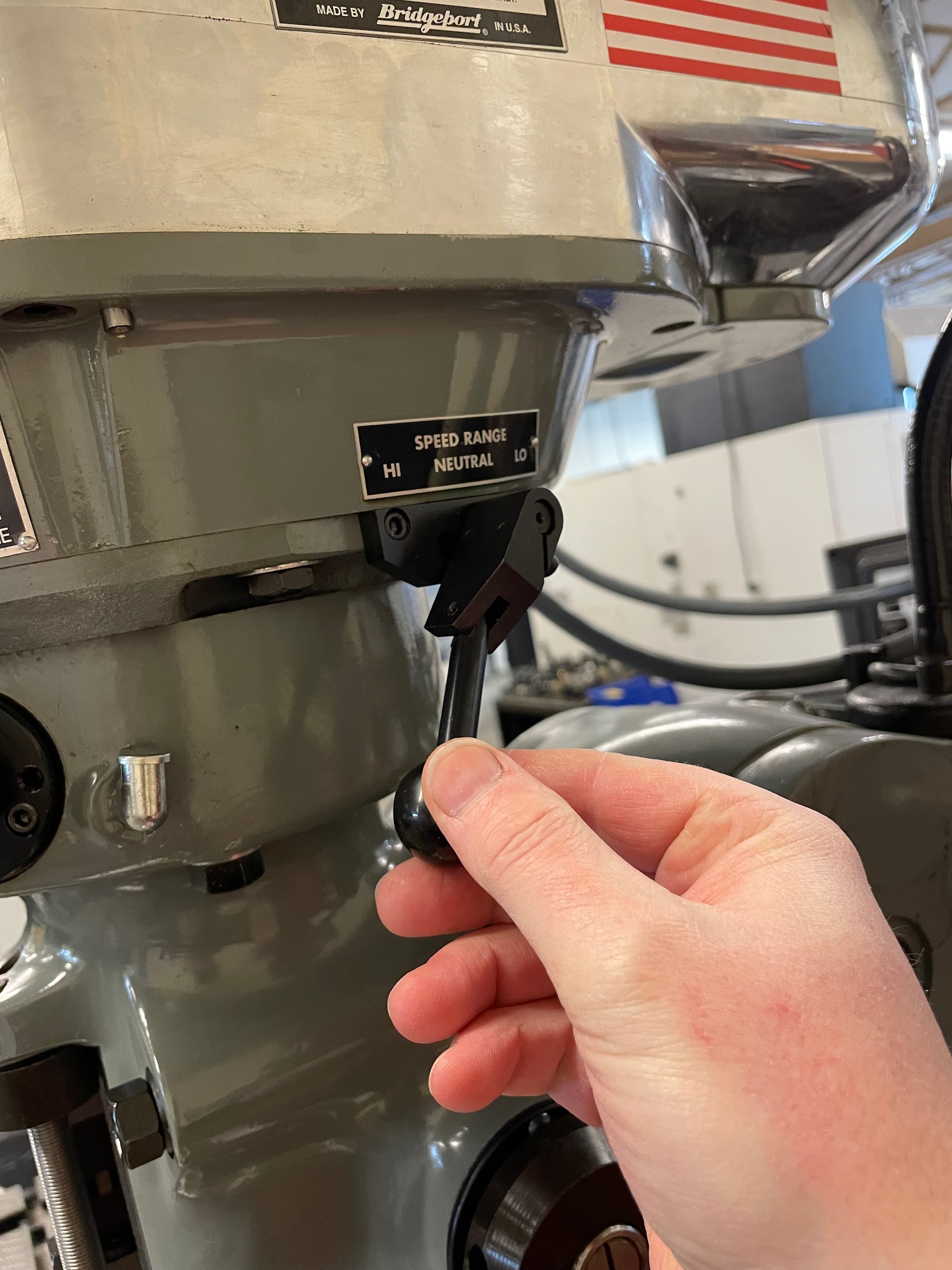
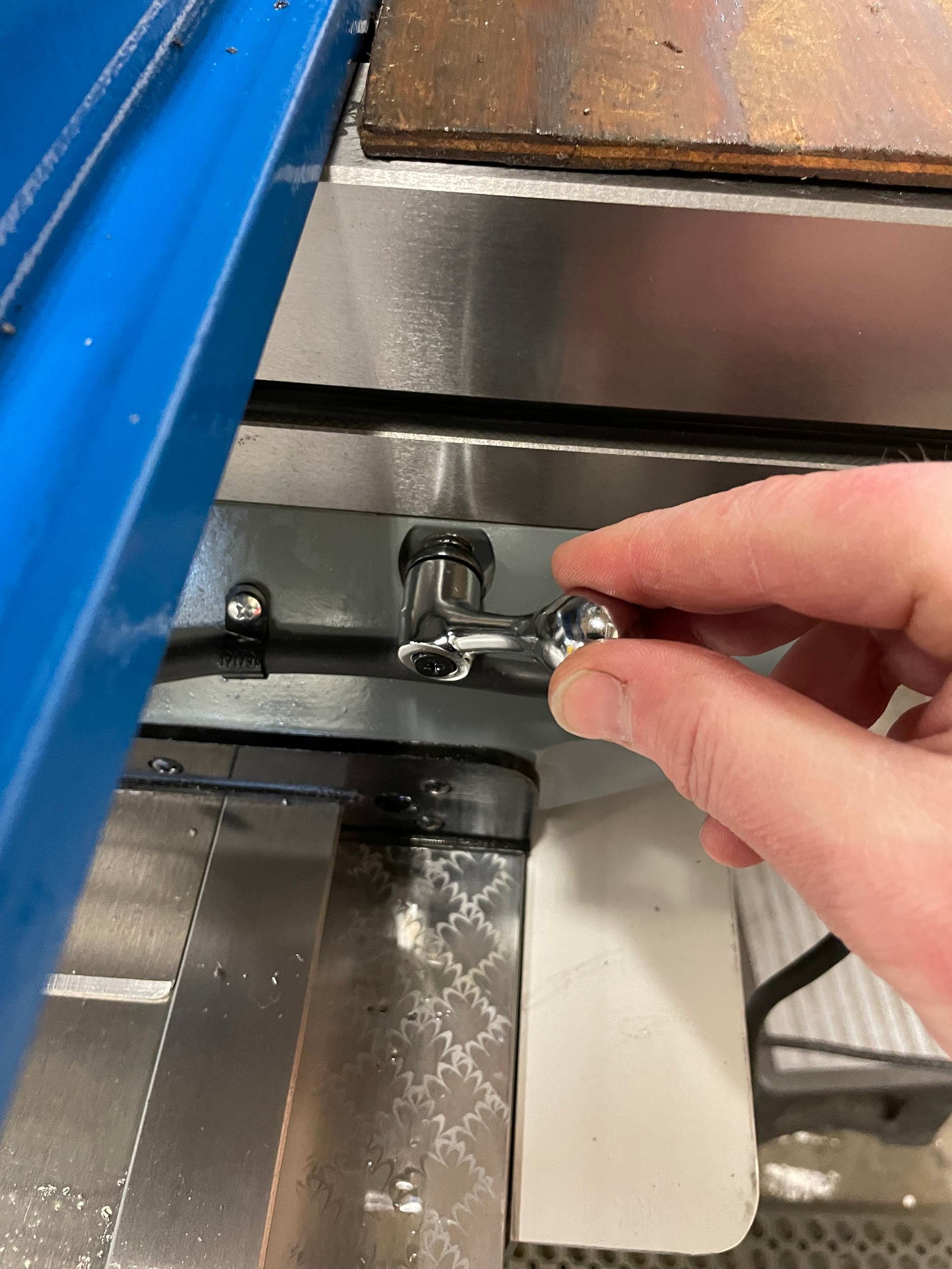
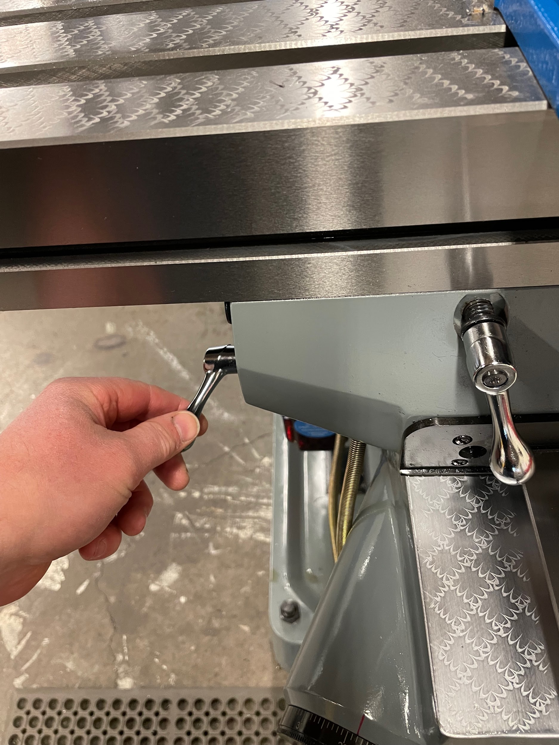
- Put the milling machine in neutral.
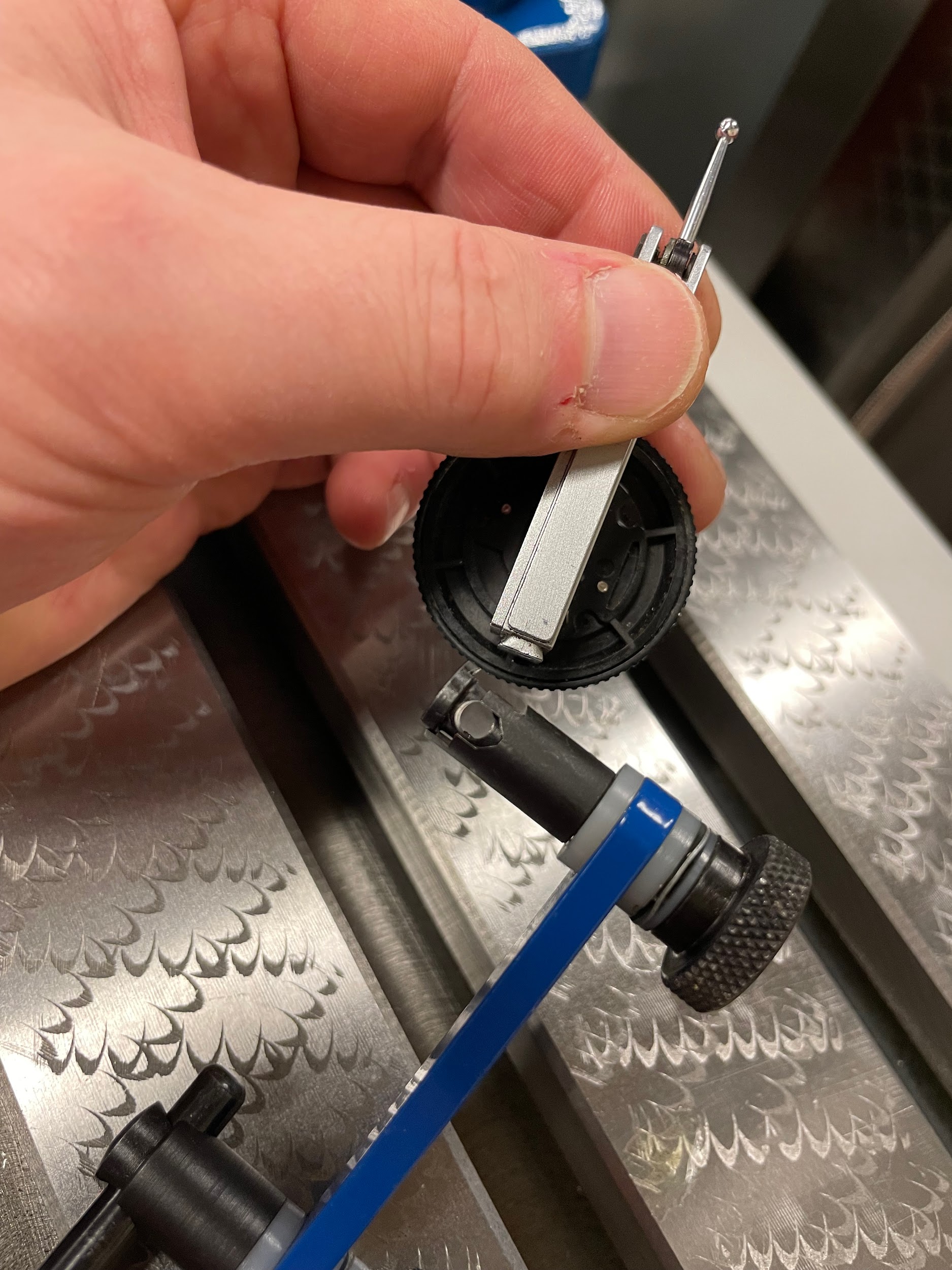
- Install a test indicator into the indicator holder.
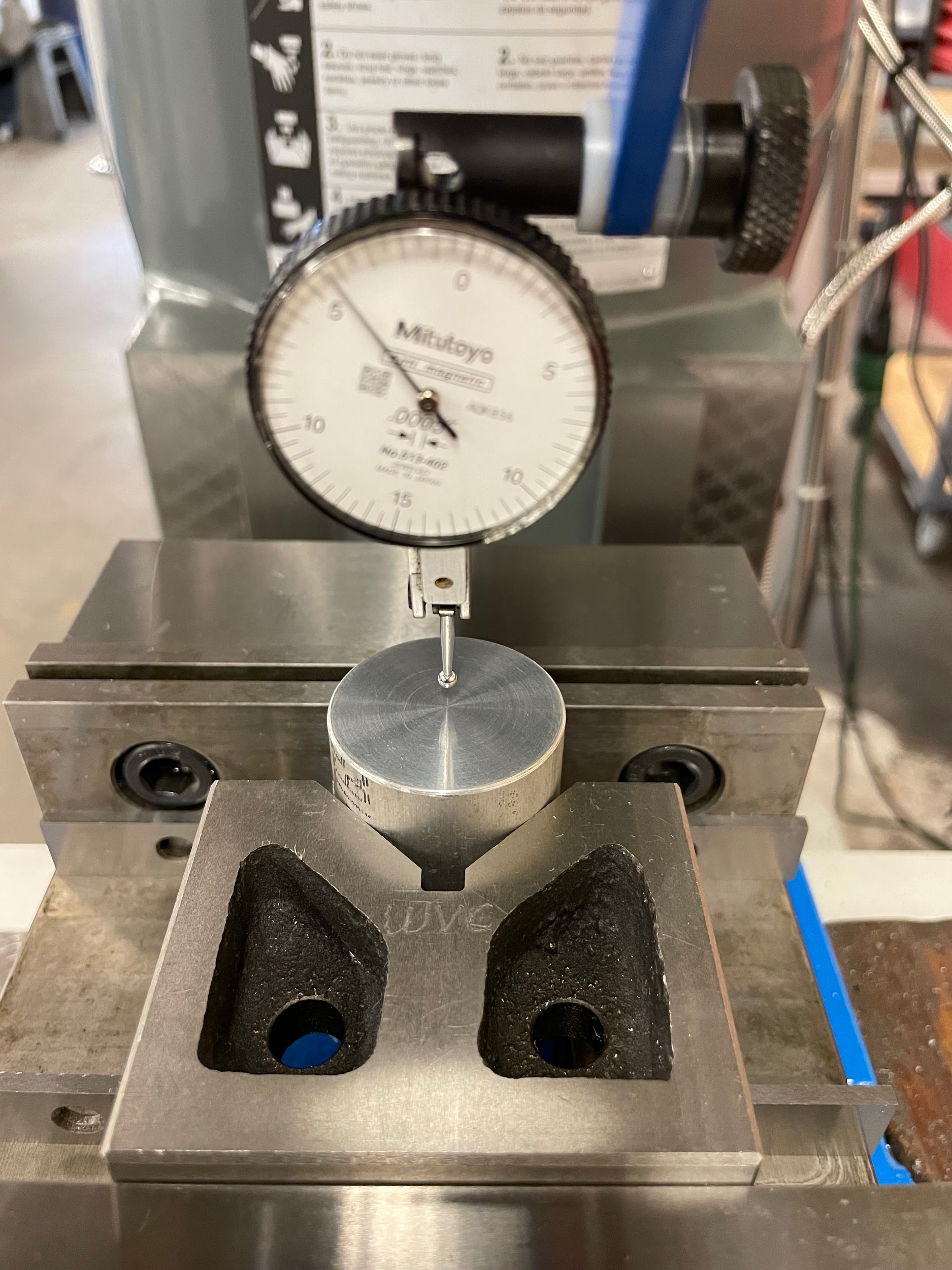
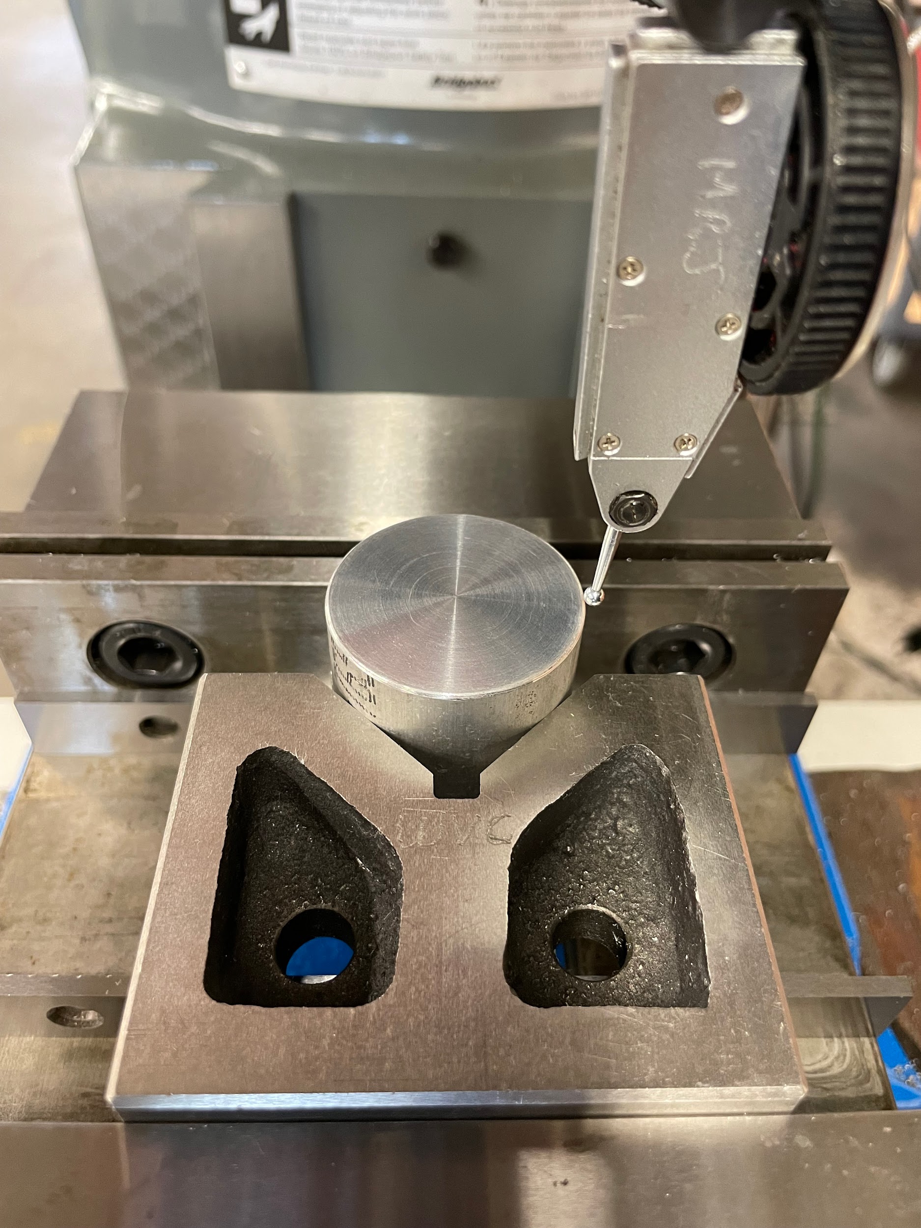
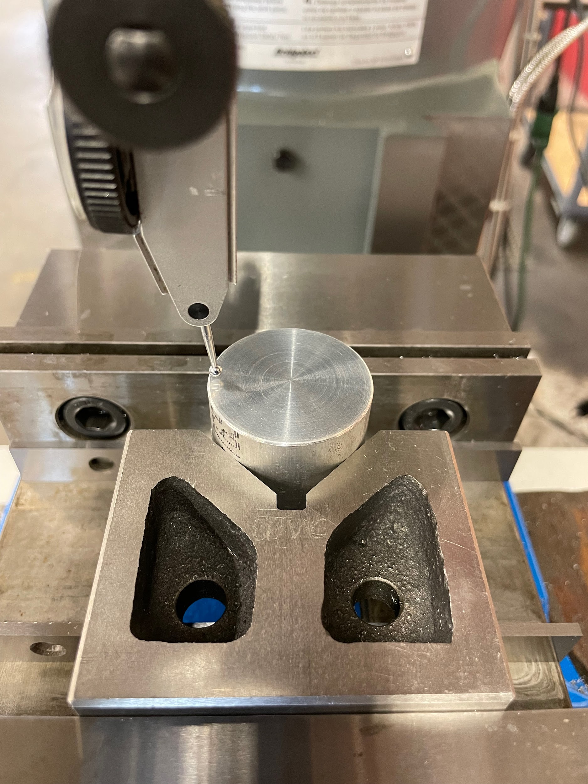
- Point the test indicator and stylus downward, directly underneath the spindle.
- Spin the spindle by hand and look at the ball on the end of the stylus. Keep adjusting the indicator and the stylus until, when spun, the ball looks like it is spinning in place. The ball is now directly in line with the center of the spindle and can be used as a pointer.
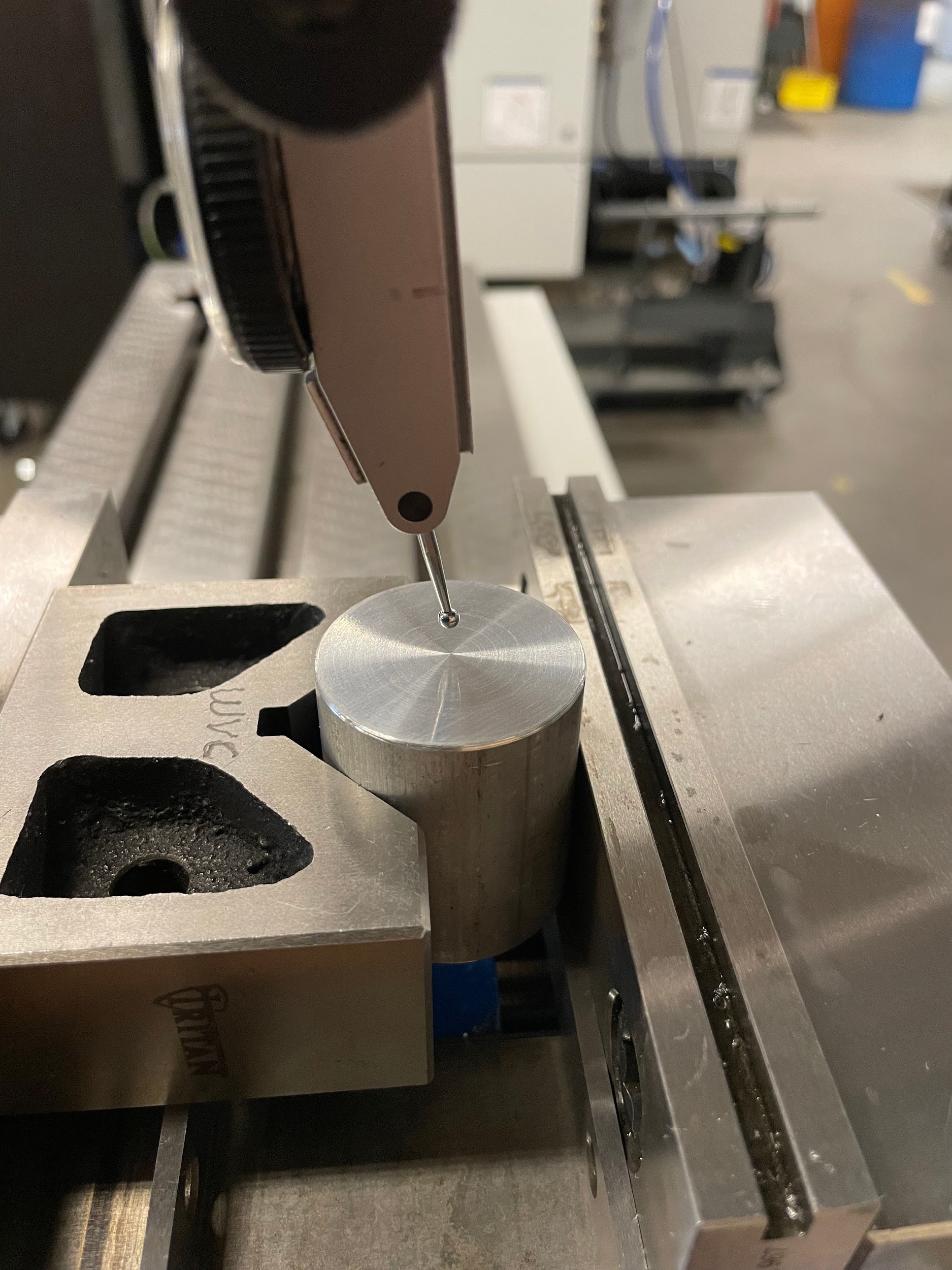
- Bring the knee and the top of the part up to about ⅛” away from the test indicator stylus ball.
- While turning the saddle and table handwheels, watch the tip of the indicator until it’s in the center of the part. Do not adjust the indicator tip or touch the indicator to the part.
- Pull the indicator out to where the stylus is, just over the edge of the part.
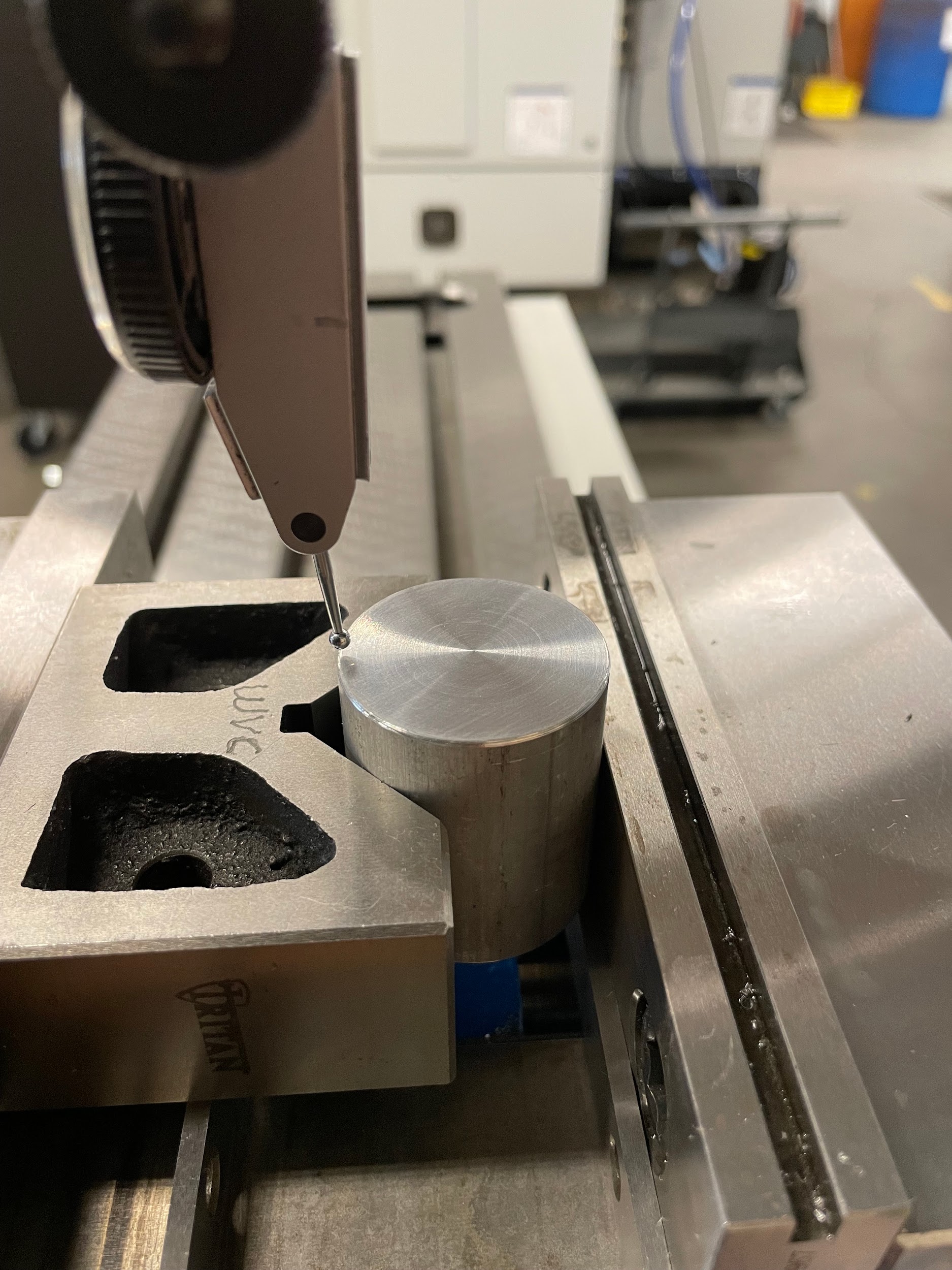
- Specifically, looking at the indicator when it is in the 12 and 6 o’clock positions, use the saddle to center the part visually between the stylus locations. Do not adjust the indicator tip or touch the indicator to the part.
- Specifically, looking at the indicator when it is in the 3 and 9 o’clock positions, use the table to visually center the part between the stylus locations. Do not adjust the indicator tip or touch the indicator to the part.
- Adjust the indicator holder and quill to allow the stylus ball to touch the side of the part. Manipulate the indicator and the holder so that when touching, the indicator is somewhere in the middle of the indicator’s travel.
- Rotate the spindle to the 6 o’clock position and zero the indicator.
- Rotate the spindle 180 degrees to read the indicator in the 12 o’clock position. A mirror can help read the indicator in this position.
- Adjust the saddle so that the indicator reads halfway between the 6 and 12 o’clock positions.
- Rotate the spindle back and forth between the 6 and 12 o’clock positions, adjusting the saddle until the readings are within .003 of each other.
- Rotate the spindle to the 3 o’clock position and zero the indicator.
- Rotate the spindle 180 degrees to read the indicator in the 9 o’clock position.
- Adjust the table so that the indicator reads halfway between the 3 and 9 o’clock positions.
- Rotate the spindle back and forth between the 3 and 9 o’clock positions, adjusting the table until the readings are within .0005 of each other.
- Go back to the 6 and 12 o’clock positions and adjust the saddle until the readings are within .0005 of each other.
- Go back and forth from saddle and table adjustments until both directions are within .0005 of each other simultaneously.
- Lock and zero both the saddle and the table. The part is now centered with the center of the spindle.
“Step 1: Install an indicator holder into or onto the spindle.”
“Step 2: Put the milling machine in neutral.”
“Step 5: Spin the spindle by hand and look at the ball on the end of the stylus. Keep adjusting the indicator and the stylus until, when spun, the ball looks like it is spinning in place. The ball is now directly in line with the center of the spindle and can be used as a pointer.”

“Step 7: While turning the saddle and table handwheels, watch the tip of the indicator until it’s in the center of the part. Do not adjust the indicator tip or touch the indicator to the part.”
“Step 7: While turning the saddle and table handwheels, watch the tip of the indicator until it’s in the center of the part. Do not adjust the indicator tip or touch the indicator to the part.”
“Step 9: Specifically, looking at the indicator when it is in the 12 and 6 o’clock positions, use the saddle to center the part visually between the stylus locations. Do not adjust the indicator tip or touch the indicator to the part.”
“Step 9: Specifically, looking at the indicator when it is in the 12 and 6 o’clock positions, use the saddle to center the part visually between the stylus locations. Do not adjust the indicator tip or touch the indicator to the part.”
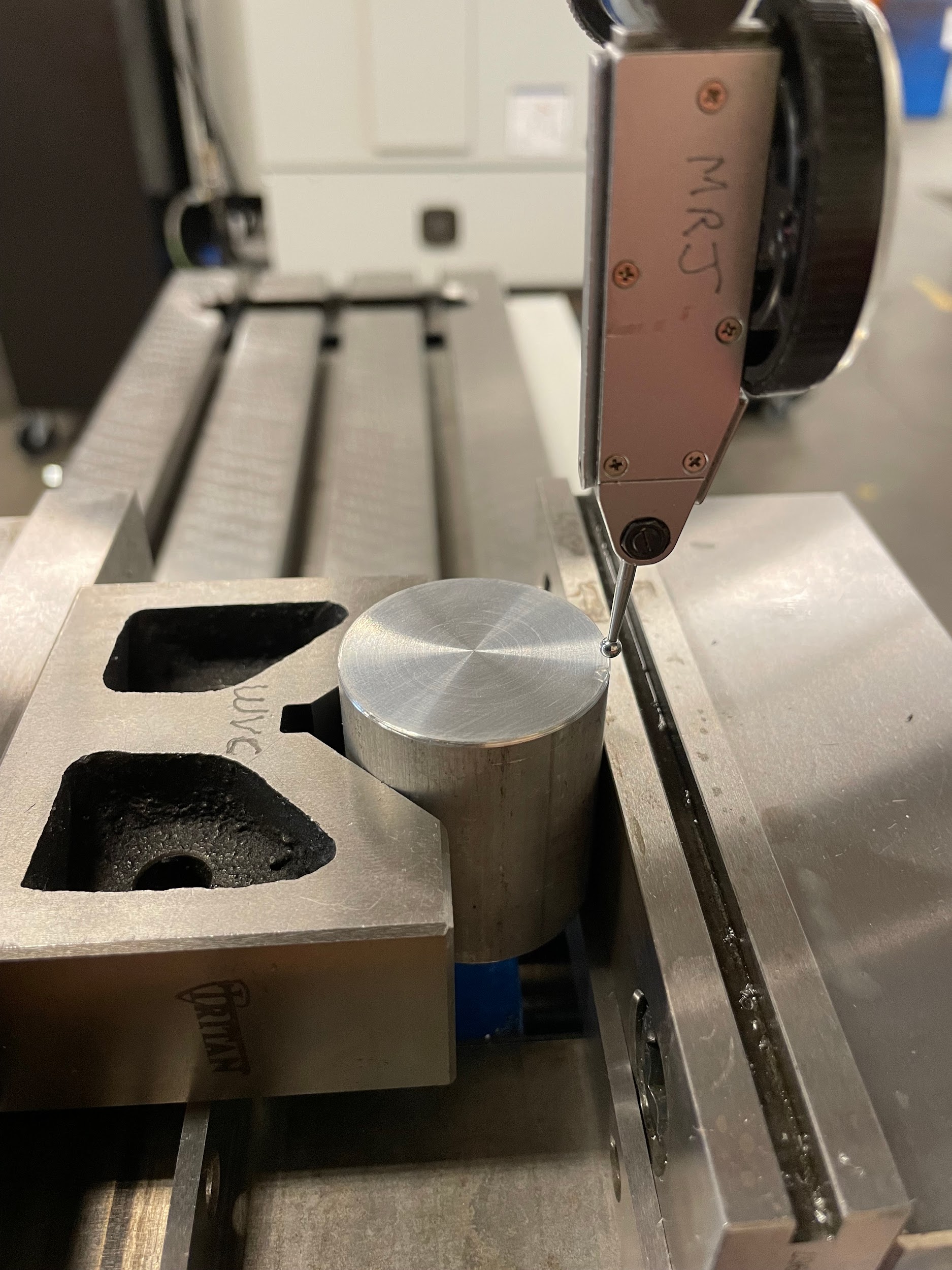
“Step 10: Specifically, looking at the indicator when it is in the 3 and 9 o’clock positions, use the table to visually center the part between the stylus locations. Do not adjust the indicator tip or touch the indicator to the part.”
“Step 10: Specifically, looking at the indicator when it is in the 3 and 9 o’clock positions, use the table to visually center the part between the stylus locations. Do not adjust the indicator tip or touch the indicator to the part.”
“Step 9-10: Specifically, looking at the indicator when it is in the 12 and 6 o’clock positions, use the saddle to center the part visually between the stylus locations. Do not adjust the indicator tip or touch the indicator to the part. Specifically, looking at the indicator when it is in the 3 and 9 o’clock positions, use the table to visually center the part between the stylus locations. Do not adjust the indicator tip or touch the indicator to the part.”

“Step 11-12: Adjust the indicator holder and quill to allow the stylus ball to touch the side of the part. Manipulate the indicator and the holder so that when touching, the indicator is somewhere in the middle of the indicator’s travel. Rotate the spindle to the 6 o’clock position and zero the indicator.”

“Step 13: Rotate the spindle 180 degrees to read the indicator in the 12 o’clock position. A mirror can help read the indicator in this position.”

“Step 14: Adjust the saddle so that the indicator reads halfway between the 6 and 12 o’clock positions.”

“Step 15: Rotate the spindle back and forth between the 6 and 12 o’clock positions, adjusting the saddle until the readings are within .003 of each other.”

“Step 19: Rotate the spindle back and forth between the 3 and 9 o’clock positions, adjusting the table until the readings are within .0005 of each other.”

“Step 22: Lock and zero both the saddle and the table. The part is now centered with the center of the spindle. ”
“Step 22: Lock and zero both the saddle and the table. The part is now centered with the center of the spindle. ”
Attributions
- Figure 9.35: Tilt and nod scales by Micky R. Jennings, courtesy of Wenatchee Valley College, for WA Open ProfTech, © SBCTC, CC BY 4.0
- Figure 9.36: Nod bolts, pivot point, and scale by Micky R. Jennings, courtesy of Wenatchee Valley College, for WA Open ProfTech, © SBCTC, CC BY 4.0
- Figure 9.37: Tilt scale and worm screw adjustment hex by Micky R. Jennings, courtesy of Wenatchee Valley College, for WA Open ProfTech, © SBCTC, CC BY 4.0
- Figure 9.38: Tilt securing nuts by Micky R. Jennings, courtesy of Wenatchee Valley College, for WA Open ProfTech, © SBCTC, CC BY 4.0
- Video 9.2: Micky R. Jennings, courtesy of Wenatchee Valley College, for WA Open ProfTech, © SBCTC, CC BY 4.0
- Figure 9.39: Indicator zero by Micky R. Jennings, courtesy of Wenatchee Valley College, for WA Open ProfTech, © SBCTC, CC BY 4.0
- Video 9.3: Micky R. Jennings, courtesy of Wenatchee Valley College, for WA Open ProfTech, © SBCTC, CC BY 4.0
- Video 9.4: Micky R. Jennings, courtesy of Wenatchee Valley College, for WA Open ProfTech, © SBCTC, CC BY 4.0
- Video 9.5: Micky R. Jennings, courtesy of Wenatchee Valley College, for WA Open ProfTech, © SBCTC, CC BY 4.0
- Figure 9.40: Adjusting the tilt nuts by Micky R. Jennings, courtesy of Wenatchee Valley College, for WA Open ProfTech, © SBCTC, CC BY 4.0
- Figure 9.41: Adjusting head tilt by Micky R. Jennings, courtesy of Wenatchee Valley College, for WA Open ProfTech, © SBCTC, CC BY 4.0
- Figure 9.42: Right side of table zero by Micky R. Jennings, courtesy of Wenatchee Valley College, for WA Open ProfTech, © SBCTC, CC BY 4.0
- Figure 9.43: Left side of table zero by Micky R. Jennings, courtesy of Wenatchee Valley College, for WA Open ProfTech, © SBCTC, CC BY 4.0
- Figure 9.44: Adjusting the nod bolts by Micky R. Jennings, courtesy of Wenatchee Valley College, for WA Open ProfTech, © SBCTC, CC BY 4.0
- Figure 9.45: Adjusting head nod by Micky R. Jennings, courtesy of Wenatchee Valley College, for WA Open ProfTech, © SBCTC, CC BY 4.0
- Figure 9.46: Back of table zero by Micky R. Jennings, courtesy of Wenatchee Valley College, for WA Open ProfTech, © SBCTC, CC BY 4.0
- Figure 9.47: Front of table zero by Micky R. Jennings, courtesy of Wenatchee Valley College, for WA Open ProfTech, © SBCTC, CC BY 4.0
- Video 9.6: Micky R. Jennings, courtesy of Wenatchee Valley College, for WA Open ProfTech, © SBCTC, CC BY 4.0
- Figure 9.48: Cleaning vise jaws by Micky R. Jennings, courtesy of Wenatchee Valley College, for WA Open ProfTech, © SBCTC, CC BY 4.0
- Figure 9.49: Installing solid jaw plate by Micky R. Jennings, courtesy of Wenatchee Valley College, for WA Open ProfTech, © SBCTC, CC BY 4.0
- Figure 9.50: Installing movable jaw plate by Micky R. Jennings, courtesy of Wenatchee Valley College, for WA Open ProfTech, © SBCTC, CC BY 4.0
- Figure 9.51: Cleaning vise base by Micky R. Jennings, courtesy of Wenatchee Valley College, for WA Open ProfTech, © SBCTC, CC BY 4.0
- Figure 9.52: Cleaning mill table by Micky R. Jennings, courtesy of Wenatchee Valley College, for WA Open ProfTech, © SBCTC, CC BY 4.0
- Figure 9.53: Installing tee nuts by Micky R. Jennings, courtesy of Wenatchee Valley College, for WA Open ProfTech, © SBCTC, CC BY 4.0
- Figure 9.54: Rough alignment of vise by Micky R. Jennings, courtesy of Wenatchee Valley College, for WA Open ProfTech, © SBCTC, CC BY 4.0
- Figure 9.55: Tightening vise securing fasteners by Micky R. Jennings, courtesy of Wenatchee Valley College, for WA Open ProfTech, © SBCTC, CC BY 4.0
- Figure 9.56: Installing test indicator on adjustable arm by Micky R. Jennings, courtesy of Wenatchee Valley College, for WA Open ProfTech, © SBCTC, CC BY 4.0
- Figure 9.57: Installing indicator on mill spindle by Micky R. Jennings, courtesy of Wenatchee Valley College, for WA Open ProfTech, © SBCTC, CC BY 4.0
- Figure 9.58: Indicator on spindle by Micky R. Jennings, courtesy of Wenatchee Valley College, for WA Open ProfTech, © SBCTC, CC BY 4.0
- Figure 9.59: Indicator close to the solid jaw by Micky R. Jennings, courtesy of Wenatchee Valley College, for WA Open ProfTech, © SBCTC, CC BY 4.0
- Video 9.7: Micky R. Jennings, courtesy of Wenatchee Valley College, for WA Open ProfTech, © SBCTC, CC BY 4.0
- Video 9.8: Micky R. Jennings, courtesy of Wenatchee Valley College, for WA Open ProfTech, © SBCTC, CC BY 4.0
- Video 9.9: Micky R. Jennings, courtesy of Wenatchee Valley College, for WA Open ProfTech, © SBCTC, CC BY 4.0
- Figure 9.60: Parallels by Micky R. Jennings, courtesy of Wenatchee Valley College, for WA Open ProfTech, © SBCTC, CC BY 4.0
- Figure 9.61: Parallels in vise by Micky R. Jennings, courtesy of Wenatchee Valley College, for WA Open ProfTech, © SBCTC, CC BY 4.0
- Figure 9.62: Part on parallels by Micky R. Jennings, courtesy of Wenatchee Valley College, for WA Open ProfTech, © SBCTC, CC BY 4.0
- Figure 9.63: Tightening a milling vise by Micky R. Jennings, courtesy of Wenatchee Valley College, for WA Open ProfTech, © SBCTC, CC BY 4.0
- Figure 9.64: Seating a part against the parallels by Micky R. Jennings, courtesy of Wenatchee Valley College, for WA Open ProfTech, © SBCTC, CC BY 4.0
- Video 9.10: Micky R. Jennings, courtesy of Wenatchee Valley College, for WA Open ProfTech, © SBCTC, CC BY 4.0
- Figure 9.65: Edge finder by Micky R. Jennings, courtesy of Wenatchee Valley College, for WA Open ProfTech, © SBCTC, CC BY 4.0
- Figure 9.66: Edge finder 2 by Micky R. Jennings, courtesy of Wenatchee Valley College, for WA Open ProfTech, © SBCTC, CC BY 4.0
- Figure 9.67: Edge finder 3 by Micky R. Jennings, courtesy of Wenatchee Valley College, for WA Open ProfTech, © SBCTC, CC BY 4.0
- Figure 9.68: Edge finder tip off-center by Micky R. Jennings, courtesy of Wenatchee Valley College, for WA Open ProfTech, © SBCTC, CC BY 4.0
- Video 9.11: Micky R. Jennings, courtesy of Wenatchee Valley College, for WA Open ProfTech, © SBCTC, CC BY 4.0
- Figure 9.69: Zeroing the table handle by Micky R. Jennings, courtesy of Wenatchee Valley College, for WA Open ProfTech, © SBCTC, CC BY 4.0
- Figure 9.70: Moving the table .100 by Micky R. Jennings, courtesy of Wenatchee Valley College, for WA Open ProfTech, © SBCTC, CC BY 4.0
- Figure 9.71: Visual check of the edge finder over the right edge by Micky R. Jennings, courtesy of Wenatchee Valley College, for WA Open ProfTech, © SBCTC, CC BY 4.0
- Video 9.12: Micky R. Jennings, courtesy of Wenatchee Valley College, for WA Open ProfTech, © SBCTC, CC BY 4.0
- Figure 9.72: Zeroing the saddle handle by Micky R. Jennings, courtesy of Wenatchee Valley College, for WA Open ProfTech, © SBCTC, CC BY 4.0
- Figure 9.73: Moving the saddle .100 by Micky R. Jennings, courtesy of Wenatchee Valley College, for WA Open ProfTech, © SBCTC, CC BY 4.0
- Figure 9.74: Visual check of the edge finder over the back edge by Micky R. Jennings, courtesy of Wenatchee Valley College, for WA Open ProfTech, © SBCTC, CC BY 4.0
- Figure 9.75: Visual check of hole position by Micky R. Jennings, courtesy of Wenatchee Valley College, for WA Open ProfTech, © SBCTC, CC BY 4.0
- Video 9.13: Micky R. Jennings, courtesy of Wenatchee Valley College, for WA Open ProfTech, © SBCTC, CC BY 4.0
- Figure 9.76: Round part held in vise by Micky R. Jennings, courtesy of Wenatchee Valley College, for WA Open ProfTech, © SBCTC, CC BY 4.0
- Figure 9.77: Installing a test indicator on the spindle by Micky R. Jennings, courtesy of Wenatchee Valley College, for WA Open ProfTech, © SBCTC, CC BY 4.0
- Figure 9.78: Shifting the mill into neutral by Micky R. Jennings, courtesy of Wenatchee Valley College, for WA Open ProfTech, © SBCTC, CC BY 4.0
- Video 9.14: Micky R. Jennings, courtesy of Wenatchee Valley College, for WA Open ProfTech, © SBCTC, CC BY 4.0
- Figure 9.79: Visually centering the test indicator stylus by Micky R. Jennings, courtesy of Wenatchee Valley College, for WA Open ProfTech, © SBCTC, CC BY 4.0
- Figure 9.80: Visually centering the test indicator stylus by Micky R. Jennings, courtesy of Wenatchee Valley College, for WA Open ProfTech, © SBCTC, CC BY 4.0
- Figure 9.81: Visually aligning the test indicator stylus by Micky R. Jennings, courtesy of Wenatchee Valley College, for WA Open ProfTech, © SBCTC, CC BY 4.0
- Figure 9.82: Visually aligning the test indicator stylus 2 by Micky R. Jennings, courtesy of Wenatchee Valley College, for WA Open ProfTech, © SBCTC, CC BY 4.0
- Figure 9.83: Visually aligning the test indicator stylus 3 by Micky R. Jennings, courtesy of Wenatchee Valley College, for WA Open ProfTech, © SBCTC, CC BY 4.0
- Figure 9.84: Visually aligning the test indicator stylus 4 by Micky R. Jennings, courtesy of Wenatchee Valley College, for WA Open ProfTech, © SBCTC, CC BY 4.0
- Video 9.15: Micky R. Jennings, courtesy of Wenatchee Valley College, for WA Open ProfTech, © SBCTC, CC BY 4.0
- Video 9.16: Micky R. Jennings, courtesy of Wenatchee Valley College, for WA Open ProfTech, © SBCTC, CC BY 4.0
- Video 9.17: Micky R. Jennings, courtesy of Wenatchee Valley College, for WA Open ProfTech, © SBCTC, CC BY 4.0
- Video 9.18: Micky R. Jennings, courtesy of Wenatchee Valley College, for WA Open ProfTech, © SBCTC, CC BY 4.0
- Video 9.19: Micky R. Jennings, courtesy of Wenatchee Valley College, for WA Open ProfTech, © SBCTC, CC BY 4.0
- Video 9.20: Micky R. Jennings, courtesy of Wenatchee Valley College, for WA Open ProfTech, © SBCTC, CC BY 4.0
- Figure 9.85: Locking the table by Micky R. Jennings, courtesy of Wenatchee Valley College, for WA Open ProfTech, © SBCTC, CC BY 4.0
- Figure 9.86: Locking the saddle by Micky R. Jennings, courtesy of Wenatchee Valley College, for WA Open ProfTech, © SBCTC, CC BY 4.0
The process of bringing the head of a manual mill to be perpendicular to both the X, and Y axis.
A device used to accurately elevate work from precision surfaces.
The process of using an edge finder to accurately locate features.
