9.8 Tool Setup
Micky R. Jennings
Setting up tooling on a milling machine requires some calculation, checks, and adjustments to make sure the cutting process will be successful. A couple of the most important things to think of when setting up tooling on a milling machine is to use the correct tool for the cut and to keep the tool setup as rigid as possible.
When selecting tools, a good rule to follow is to use the largest diameter and shortest tool that will be able to complete the job. Keep in mind that end mills are the most common cutting tool and generally come in sizes from ⅛” to ¾” for manual milling. If the print requires a deep cut with a lot of metal removal, a larger diameter tool will be more rigid and remove the material faster than a smaller diameter tool. If the print requires a narrow, shallow cut, a shorter tool would be better suited for the cut than a long tool because it will be more rigid and cut more accurately with fewer problems.
When loading the tool, the operator must think of how to optimize the rigidity of the tool they have selected. The operator should choose a type of holder that is capable of holding the cutting forces of the tool. End mills should never be put into a drill chuck. When installing the tool into the tool holding device, the operator should engage as much of the solid shank of the tool as possible, generally within ⅛” of the flutes. Likewise, the tool should never be gripped over the flutes of the cutting edges.
Loading Tools into and Removing Tools from the Milling Machine
As with all machining setups, cleanliness is going to be key when loading tools into the milling machine. Clean tools and holders reduce the chance of damage and help maintain the accuracy of the spindle and tooling. Modern manual milling machines utilize an R8 taper and a draw bar for securing tooling. Some tools, such as endmills, are held in R8 tool holders or R8 collets. Other tools, such as face mills, may be held by an integral R8 shank that is part of the tool itself. Twist drills are usually held in drill chucks, unless there is a specific need to hold the tool tighter, and there is a collet in the same size as the drill shank. Holding a reduced shank drill in a ½” collet is a good example of this instance.
For safety, a box end wrench or vise handle is not recommended when tightening the draw bar. An open-ended wrench is safer because it cannot be accidentally left on the draw bar and, inadvertently, have the machine turned on. Not heeding this warning could result in the operator being injured, the machine becoming damaged, or the tooling being broken.
The following process is for loading and unloading tools from a milling spindle with an R8 spring collet as the holding device. The process is similar for loading integral shank R8 tools or end mill holders. The main difference is that end mill holders should have tools installed and removed from the machine before being installed into the spindle. On specific machinery in the shop, tightening or loosening tools in tool holders while in the spindle could be a hazard to the operator. This is a habit that should not be started.
Step by step process for loading a tool in a collet:
- Gather the tool, the appropriately sized collet for the shank of the cutting tool, and the ¾” open ended drawbar wrench.
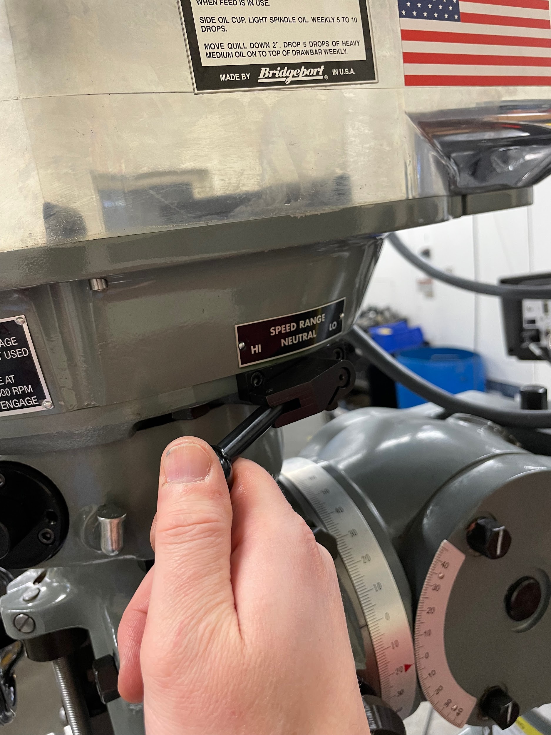
- Put the milling machine in gear if it isn’t already. If the machine is in neutral, the brake mechanism will not function.
- With a clean finger, reach inside the spindle and wipe the R8 taper clean.
- With a clean hand, wipe any chips, dust, or debris from the R8 taper, the keyway, and the precision diameter at the top near the threads.
- Insert the collet into the spindle, gently rotating it to align the keyway with the pin inside the spindle.
- Push the collet all the way up into the spindle to where the tapers meet.
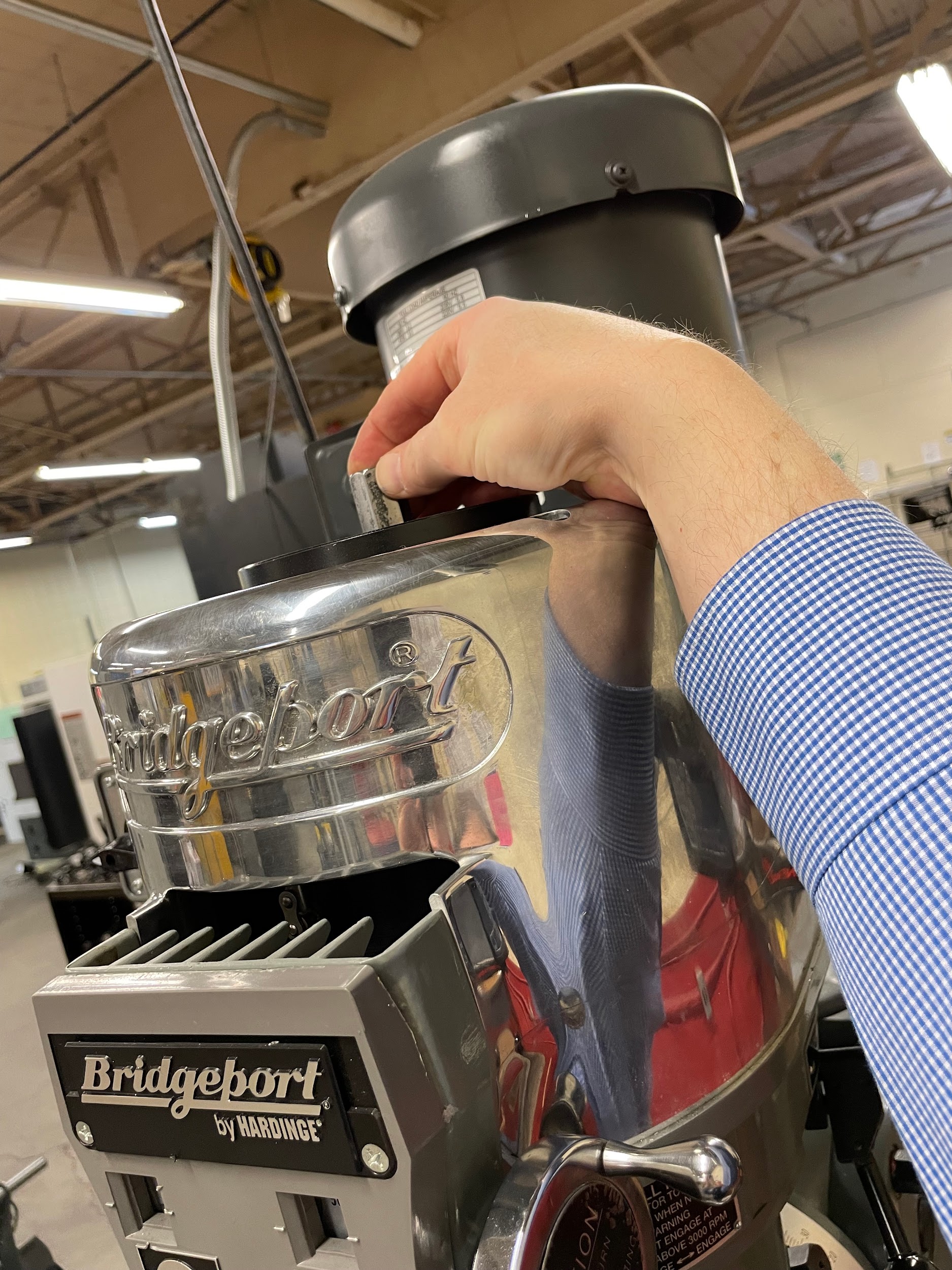
- Hold the collet with the left hand, reach up to the top of the machine with the right hand, and engage the draw bar with a few rotations. The collet is now being held in the spindle by the end of the draw bar.
- Insert the tool into the collet.
- Again, push the collet and tool up to where the tapers meet. This makes tightening the draw bar easier.
- Tighten the draw bar by hand while supporting the tool.
- Still supporting the tool, use the ¾” open ended wrench to tighten the draw bar until the spindle starts spinning.
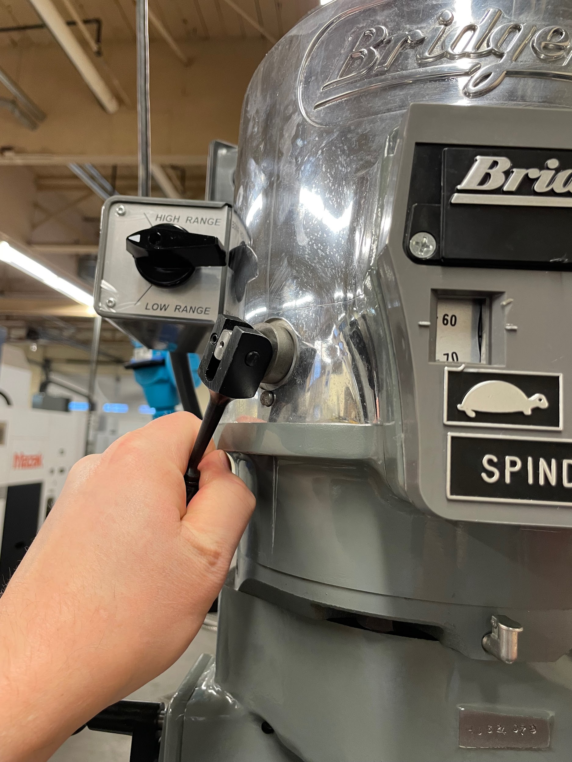
- Grab and apply the spindle brake while continuing to tighten the draw bar until the appropriate torque is reached.
Step 2: Put the milling machine in gear if it isn’t already. If the machine is in neutral, the brake mechanism will not function.
Step 7: Hold the collet with the left hand, reach up to the top of the machine with the right hand, and engage the draw bar with a few rotations. The collet is now being held in the spindle by the end of the draw bar.
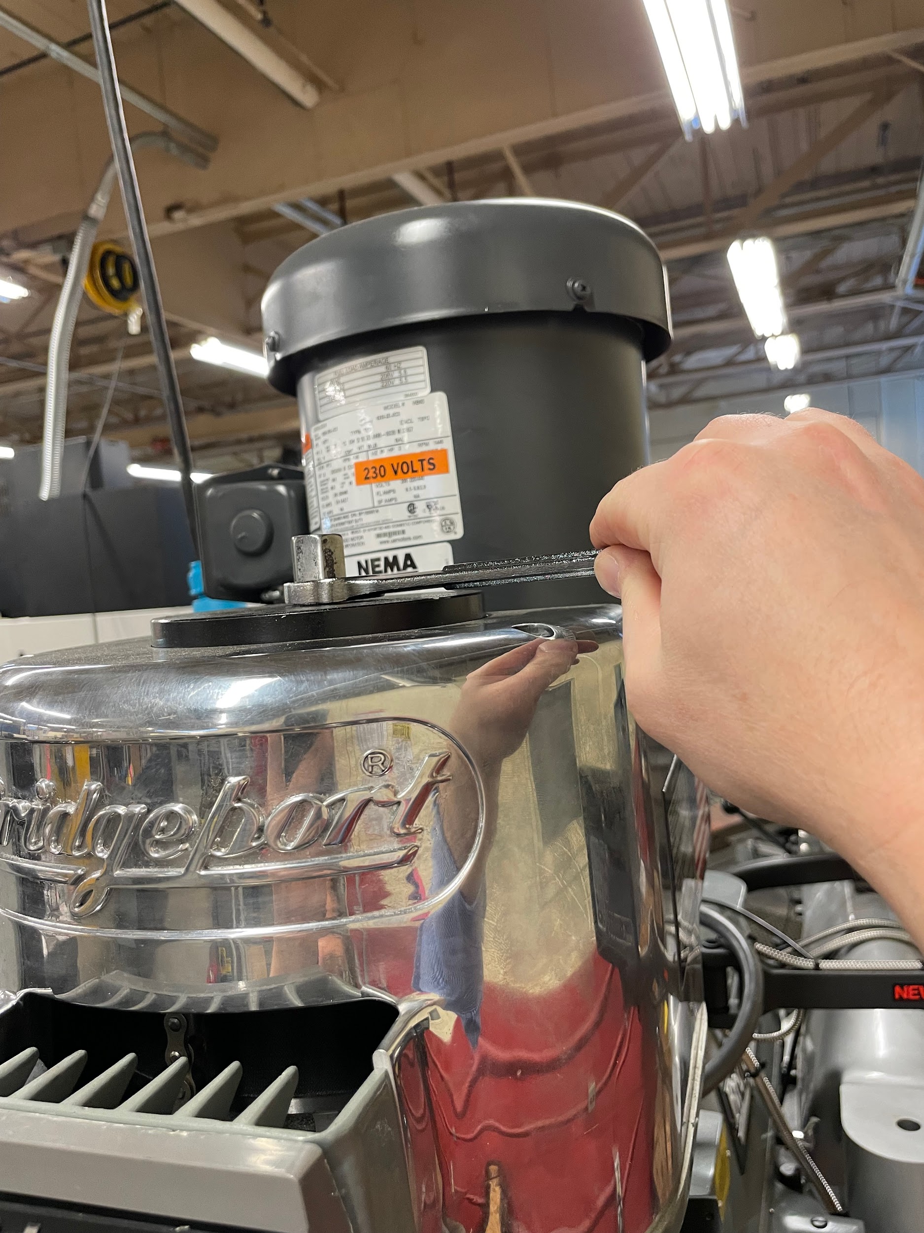
Step 11: Still supporting the tool, use the ¾” open ended wrench to tighten the draw bar until the spindle starts spinning.
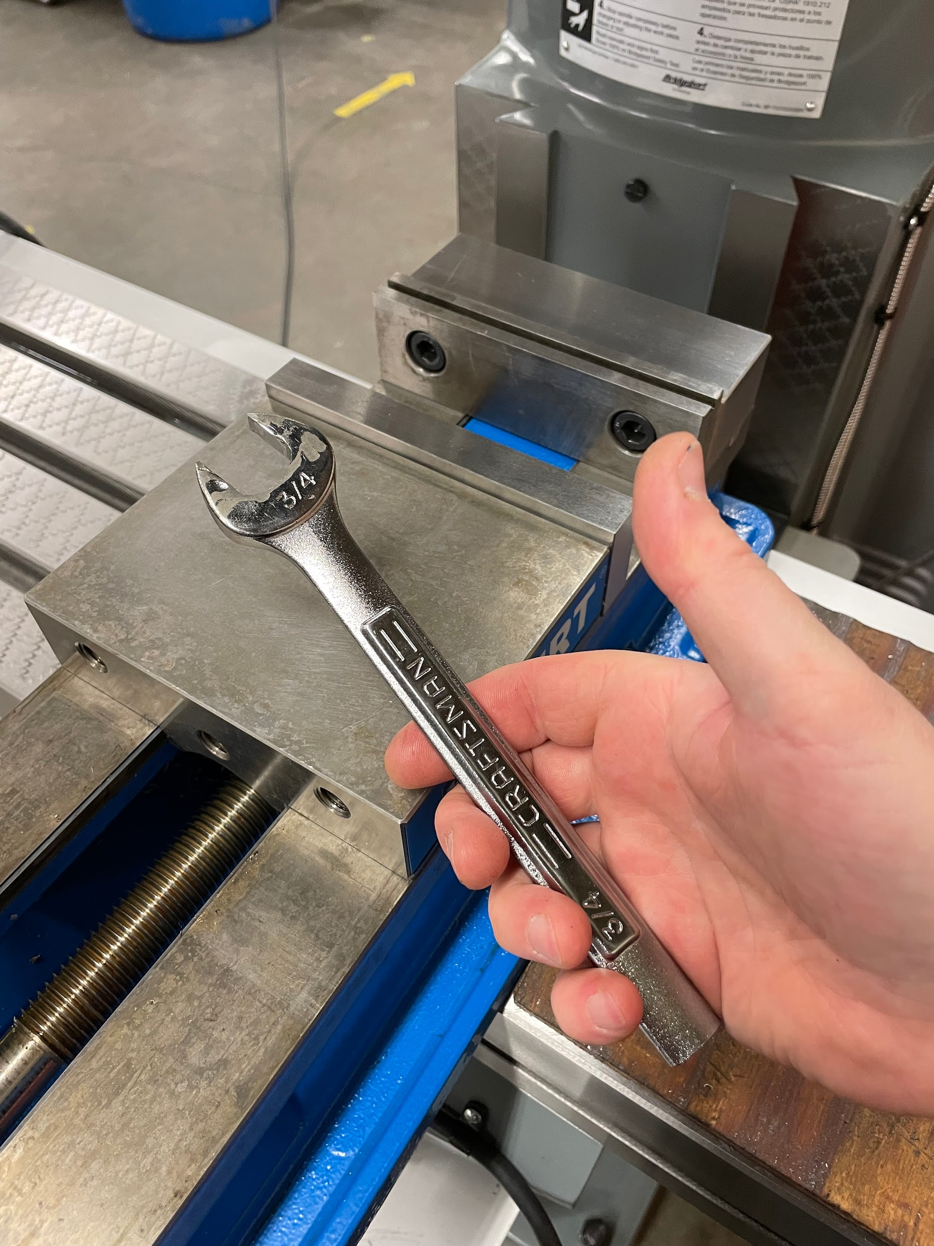
Figure 9.129. A hand holds a ¾” open ended wrench to be used for tightening and loosening the draw bar of the milling machine. / Image Credit: Micky R. Jennings, courtesy of Wenatchee Valley College, CC BY 4.0
Step 12: Grab and apply the spindle brake while continuing to tighten the draw bar until the appropriate torque is reached.
Step 12: Grab and apply the spindle brake while continuing to tighten the draw bar until the appropriate torque is reached.
Step by step process for unloading a tool from a collet:
- Grab and apply the spindle brake while loosening the draw to hand tight with an open ended ¾” wrench. Be careful not to loosen the draw bar too much while holding the brake, as the tool may fall out of the collet, and become damaged.
- Place the left hand under the tool to support it and the collet.
- Continue to loosen the draw bar with the wrench until it can be easily turned by hand.
- Once the draw bar is loose, unscrew it one full turn. Do not unscrew the draw bar all the way, or the last thread will become damaged in the next step.
- While still supporting the tool, forcefully tap on the top of the draw bar with the side of the metal wrench to break the R8 taper loose. The tool will now slide out of the collet and should be removed and set aside.
- Still supporting the collet with the left hand, fully unscrew the draw bar with the right until the collet can be removed from the spindle.
- Return the collet to the storage rack.
Attributions
- Figure 9.127: Shift mill into gear by Micky R. Jennings, courtesy of Wenatchee Valley College, for WA Open ProfTech, © SBCTC, CC BY 4.0
- Figure 9.128: Turning the draw bar by Micky R. Jennings, courtesy of Wenatchee Valley College, for WA Open ProfTech, © SBCTC, CC BY 4.0
- Figure 9.129: Open ended wrench by Micky R. Jennings, courtesy of Wenatchee Valley College, for WA Open ProfTech, © SBCTC, CC BY 4.0
- Figure 9.130: Milling head brake by Micky R. Jennings, courtesy of Wenatchee Valley College, for WA Open ProfTech, © SBCTC, CC BY 4.0
- Figure 9.131: Draw bar tightening by Micky R. Jennings, courtesy of Wenatchee Valley College, for WA Open ProfTech, © SBCTC, CC BY 4.0
