Readings Specific to Lab Assignments
Lab 1: Home Security Alarm System
Introduction to Microcontroller-Based Security Systems
Microcontroller-based security systems have become increasingly popular for home and business applications due to their flexibility, cost-effectiveness, and ability to integrate multiple sensors and outputs. The PIC16F18875 microcontroller is well-suited for this type of project due to its ample I/O pins, built-in timers, and analog-to-digital conversion capabilities.
Key Components and Concepts
- Sensor Inputs:
- Door/window sensors (magnetic reed switches)
- Motion detectors (PIR sensors)
- Glass break detectors
- User Interface:
- Keypad for arming/disarming (3-digit code)
- LCD display for system status
- Outputs:
- LEDs for visual indicators
- Piezo buzzer or siren for audible alarm
- Relay for external siren control
- Timing Considerations:
- Entry/exit delays (30 seconds)
- Alarm activation delay (15 seconds)
- State Machine:
- Disarmed state
- Armed state
- Alarm triggered state
Implementation Tips
- Use interrupts for sensor inputs to ensure quick response times.
- Implement debouncing for keypad inputs to avoid false triggering.
- Use timer interrupts for managing delays and timing functions.
- Store the security code in EEPROM for persistence across power cycles.
- Use a state machine approach to manage system behavior in different modes.
Assembly Language Considerations
- Use meaningful labels and comments to improve code readability.
- Utilize macros for repeated code segments to improve maintainability.
- Be mindful of register bank selection when accessing special function registers.
- Use bit-wise operations for efficient handling of individual I/O pins.
Lab 2: Temperature Indicator
Introduction to Analog Temperature Sensing
The MCP9701 is a linear active thermistor integrated circuit that provides a voltage output proportional to temperature. By using the PIC16F18875’s analog-to-digital converter (ADC), we can measure this voltage and convert it to a temperature reading.
Key Components and Concepts
- MCP9701 Temperature Sensor:
- Linear output: 19.5mV/°C (scale factor)
- 500mV output at 0°C (offset voltage)
- Analog-to-Digital Conversion:
- 10-bit ADC on PIC16F18875
- Voltage reference selection
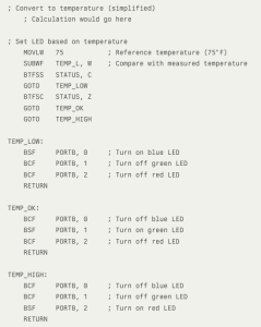
- Temperature Calculation:
- Converting ADC reading to voltage
- Applying scale factor and offset to calculate temperature
- LED Indicators:
- Red LED for high temperature
- Blue LED for low temperature
- Green LED for on-target temperature
Implementation Tips
- Configure the ADC for the appropriate voltage reference and acquisition time.
- Use averaging of multiple ADC readings to reduce noise.
- Implement hysteresis to prevent rapid switching between temperature states.
- Use floating-point calculations for accurate temperature conversion.
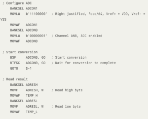
Assembly Language Considerations for ADC
- Configure ADC control registers (ADCON0, ADCON1, etc.) appropriately.
- Use bit-setting instructions to start conversions and check for completion.
- Implement proper timing delays for ADC acquisition and conversion.
- Handle 10-bit results correctly, considering result formatting (left/right justified).
Sample Code Snippet (PIC16F18875 Assembly)
Deepen your understanding: Watch the accompanying lecture video to delve deeper into the concepts covered in the reading.
