2 Chapter 2: How to Learn to Read Blueprints
Cary Flanigan
Blueprints are 2-dimensional architectural design drawings that indicate the size of a planned building, the materials to be used in its construction, and the placement of its features. Learning to read blueprints is essential not only for construction workers but also for the people who hire architects to draft them.
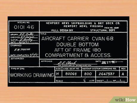
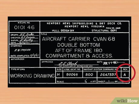
- The title block’s first section lists the blueprint’s name, number, as well as the location, site, or vendor. If the drawing is part of a series this information will also be listed. This section is largely for filing and organizational purposes.
- The second section comprises bureaucratic information. Approval dates and signatures are located here. If you find a blueprint that interests you and want to know more, this information can be invaluable.
- Section three of the title block is the list of references. This lists all other drawings that are related to the building/system/component, as well as all blueprints that were used as reference/inspiration. Similar to the second section this can be incredibly helpful if you are to begin your own blueprint.
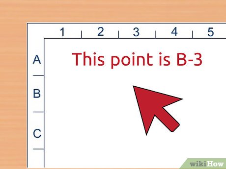
If you are looking over the drawings with a team or partner and can’t physically point to the location you’re discussing, grid systems are very useful. This could be the case if you working online from different locations, or the other person/people simply isn’t in the room with you.
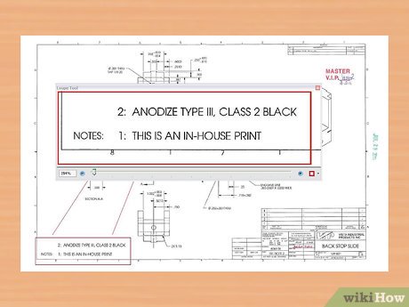
- For projects that actually begin construction it is even more important to read the notes. It’s possible practical information like, “Do not begin working until 8am,” will be listed.
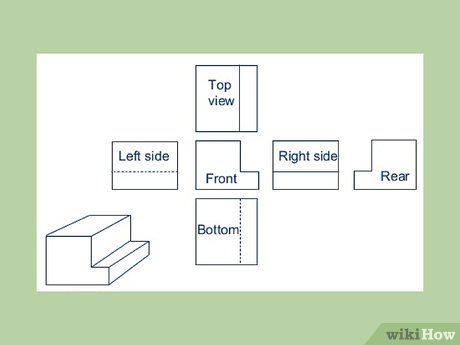
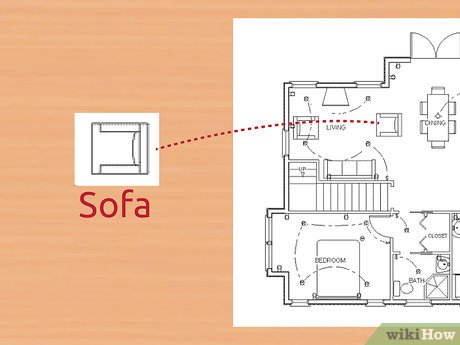
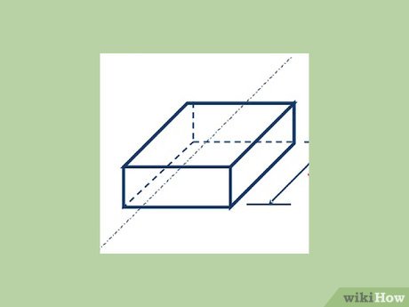
- Plan: A bird’s eye view of planned work. Usually this is done on a horizontal plane at 30″ above the floor. This perspective allows precise mapping of width and length.
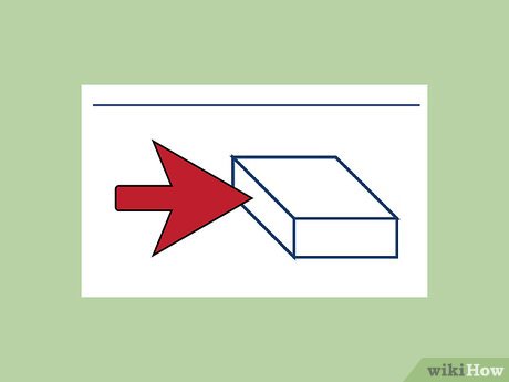
- Elevation: A view of planned work from the side. These drawings are usually oriented from the north, east, west, or south. Composing an elevation map allows for detailed planning of height dimensions.
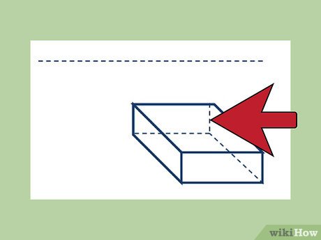
- Section: A view of something as if it were cut through. This perspective is generally imaginary, and is used to show the inner workings of how something will be built.
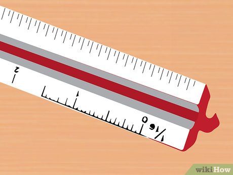
- Architectural scales are used for the construction of building exterior and interiors; for establishing doors, windows, and walls. Many are presented in fractions: 1/4″ = 1′ (one-fourth inch equals one foot), 1/8″ = 1′ (one-eighth inch equals 1 foot).
- Engineer scales, or civil scales, are used for public water systems, roads and highways, as well as topographical endeavors. They use whole-integer ratios like 1″ = 10′ (one inch equals 10 feet) or 1″ = 50′ (one inch equals fifty feet).
- There are a variety of scales that might appear on blueprints. Common scales in the US include 1/4″=1′ and 3/32″=1′.
- The blueprints should always include a door and window schedule. This will state the style, size, and material of each door and window.
- You should see the finish schedule included. This will tell you what style or model each appliance is.
Blueprint Lines
- Object Line
- Hidden Line
- Center Line
- Extension and Dimension Line
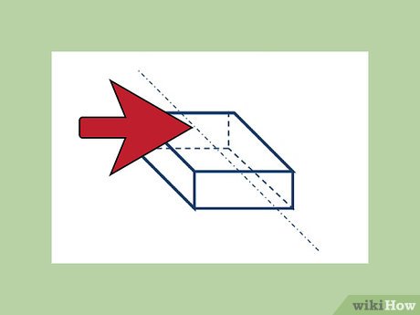
- Cutting Plane Lines
- Section Line
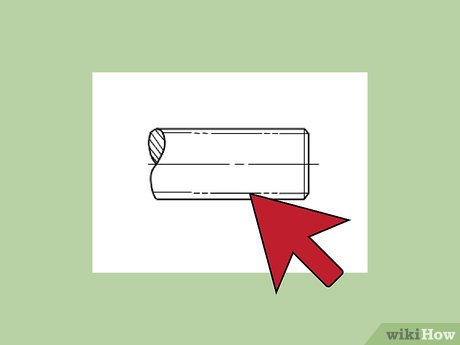
- Break Lines
- Phantom Line
- One rule of hidden lines is that they must always begin in contact with the line that is their starting point. The exception to this is anytime that first dash would appear to be a continuation of a solid line.
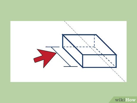
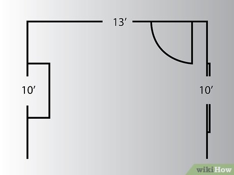
- Dimension lines will help to envision a more 3D space and maintain correct spacing within a room or object.
- Center lines are drawn with the same weight as invisible lines.
- Phantom lines also show any detail that needs to be repeated, or even the location of absent parts.
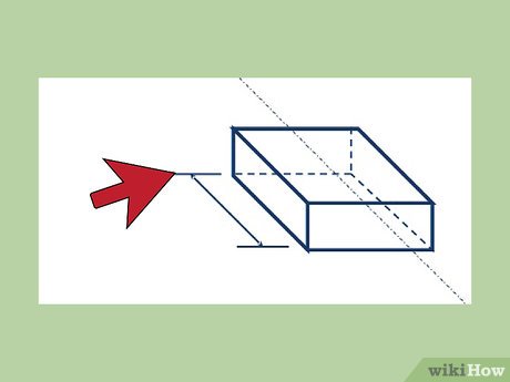
- Since dimension lines often have to hover above an object simply because there is no room on the paper, or they would overlap, extension lines allow for more definite end and beginning points.
- Dimension lines are drawn with the same weight as invisible lines.
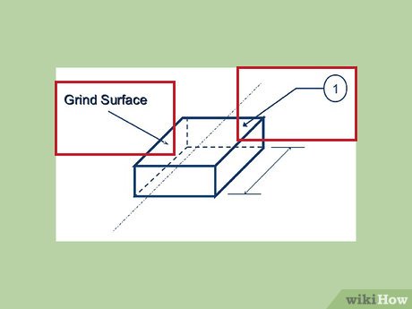
- Desks, bookcases, and other furniture that don’t come pre-assembled are a common reference to remember leader lines. In the instruction manual, lead lines are frequently used to define parts (i.e. “Place slot A into hole B”).
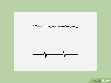
- Short break lines are done freehand and resemble a solid, thick sin wave.
- Long break lines are long, thin ruler-produced lines interspersed with freehand zig-zags.
Tips
-
When first learning how to read blueprints, take your time reading them. Look over individual words and symbols to understand their purposes before moving on to other parts of the blueprint. You may want to highlight individual parts as you figure out their meanings.
This chapter is an excerpt from a Wikihow article and was co-authored by Mark Spelman. Mark Spelman is a General Contractor based in Austin, Texas. With over 30 years of construction experience, Mark specializes in constructing interiors, project management, and project estimation. He has been a construction professional since 1987.
