6.8 Application
Tim A. Bacon
Reading the drawing
When looking at the technical drawing, specific information such as tolerances, and finish requirements will help determine the process used to create the part. It is important to note that tolerance can be viewed subjectively. A person cutting blocks of material to be supplied to a machine shop may usually have +/-.06 for tolerance. So, a job requiring a tolerance of +/-.01 would require extra attention and effort to achieve. At another shop, machinists may routinely make parts that are +/-.001. To them, a +/-.01 is nothing to worry about.
The drawing will typically state the type of material required for the part. A machinist could choose the material if it was for a fixture to be used on a job. (This is the case for the bench block exercise.) Some customers may provide the material that is to be used for the job. This may happen because the material is expensive. When the material is provided, there isn’t any extra material in case a mistake happens. If this is the situation, it is allowable for the machinist to again choose a piece of material to make a first part, provided that it is clearly marked as a setup part. The part must say “set up” or NCM (non-conforming material) on all sides and be visible at all times. Remember, ensure you have the correct material before starting. Whenever you are unsure, ask, and take notes so you don’t have to ask again.
Making a part for the first time, even for a Journeyman Machinist, is a learning process. Making mistakes is part of the learning process. If a mistake is made, try to save the part by repairing it. This task will rely on and improve problem solving abilities. Learning from the choices made will also aid in future decisions.
| Sequence | Feature | Holding | Machine | Tooling | Notes |
|---|---|---|---|---|---|
| 1 | Grind | Magnetic Chuck | Surface grinder | N/A | Minimal material removal |
| 2 | Spot drill | Vice with parallels | Vertical mill | Add step to square up stock | N/A |
| 3 | Drill | Vice with parallels | Vertical Mill | N/A | N/A |
| 4 | Bore | Vice with parallels | Vertical Mill | Adjustable boring head | N/A |
| 5 | Groove | Vice with parallels | Vertical Mill | Flat end mill | Tilt head to 45 deg |
| 6 | Counter bore | Vice with parallels | Vertical Mill | Flat end mill | Rotary table |
| 7 | Profile | Through holes with fixture in three jaw | Vertical Mill | Flat end mill | Rotary table |
| 8 | Knurl | Through holes with fixture in three jaw | Lathe | Pinch knurl tool | N/A |
| 9 | Turn | Through holes with fixture in three jaw | Lathe | Turning tool | N/A |
| 1.5 | Square up stock | Vice | Vertical Mill | Face mill | N/A |
| option | Counter bore | Three jaw chuck or form jaws | Lathe | Boring bar | N/A |
| option | Profile | Through holes with fixture in three jaw | Lathe | Turning tool | N/A |
Here are the steps to create an individualized project plan:
- Create a spreadsheet for the different features that need to be cut.
- Set up a table with five columns on the page.
- List the different features that need to be cut in the first column. For example, having holes in a part will require a spot drill to start the hole.
- Select the appropriate drill to complete the hole. The size after drilling will indicate whether or not a boring bar is needed to make the hole larger to meet the dimensions on the drawing.
- Organize the list into a sequence. For example, the holes need to be spot drilled before drilling through the part.
The second column describes how to hold the part. The third column will specify the machine where the work is being done. The fourth column will be for tooling. The final column is used for any specific notes. A special note might be to call out a specialized piece of equipment, such as a rotary table. The rotary table can be mounted on a mill with a vise on top of the table. By turning the handle, an arc or circle can be created when milling.
Number the features to indicate the sequence in which they will be cut. This process may have to be rewritten a few times until the order makes sense. Creating a job plan is ultimately about identifying the steps to complete a project and deciding the best order for the steps. Consider this: If a square piece of material is cut into a circle, it will require more work and special tooling to hold the part while working on it. Similarly, if the V groove is cut before the holes are drilled, when the drill starts to cut into the V, it will bend and move off of its location. This will damage the tool, the part, or both. Considering the order of actions is essential.
Minimal material is to be removed on the large sides of the square. Cutting the scale off the material may take up to .05 inches from the overall thickness. Grinding should be used for this step to retain the most material possible.
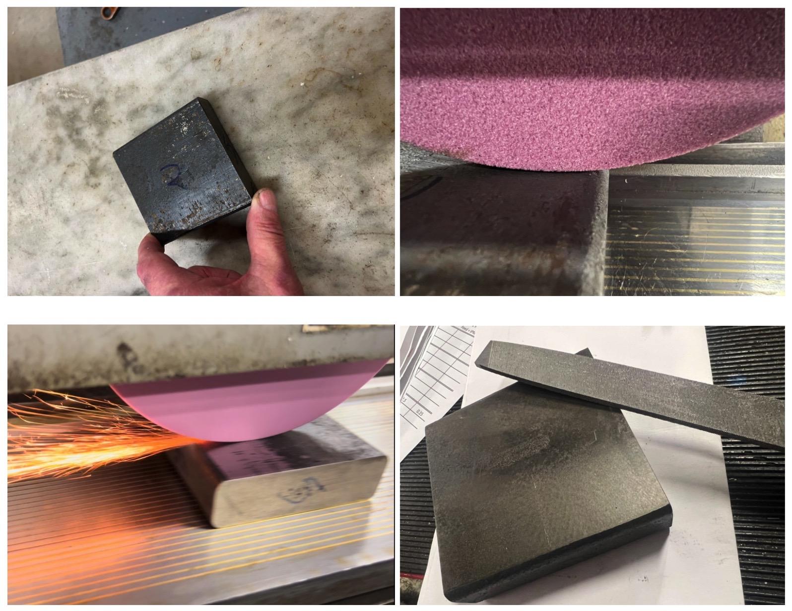
Cut the four 1.0 inch thick sides of the square so that the opposite sides are parallel. This will allow the part to be better held in a vise so that further work can be done.
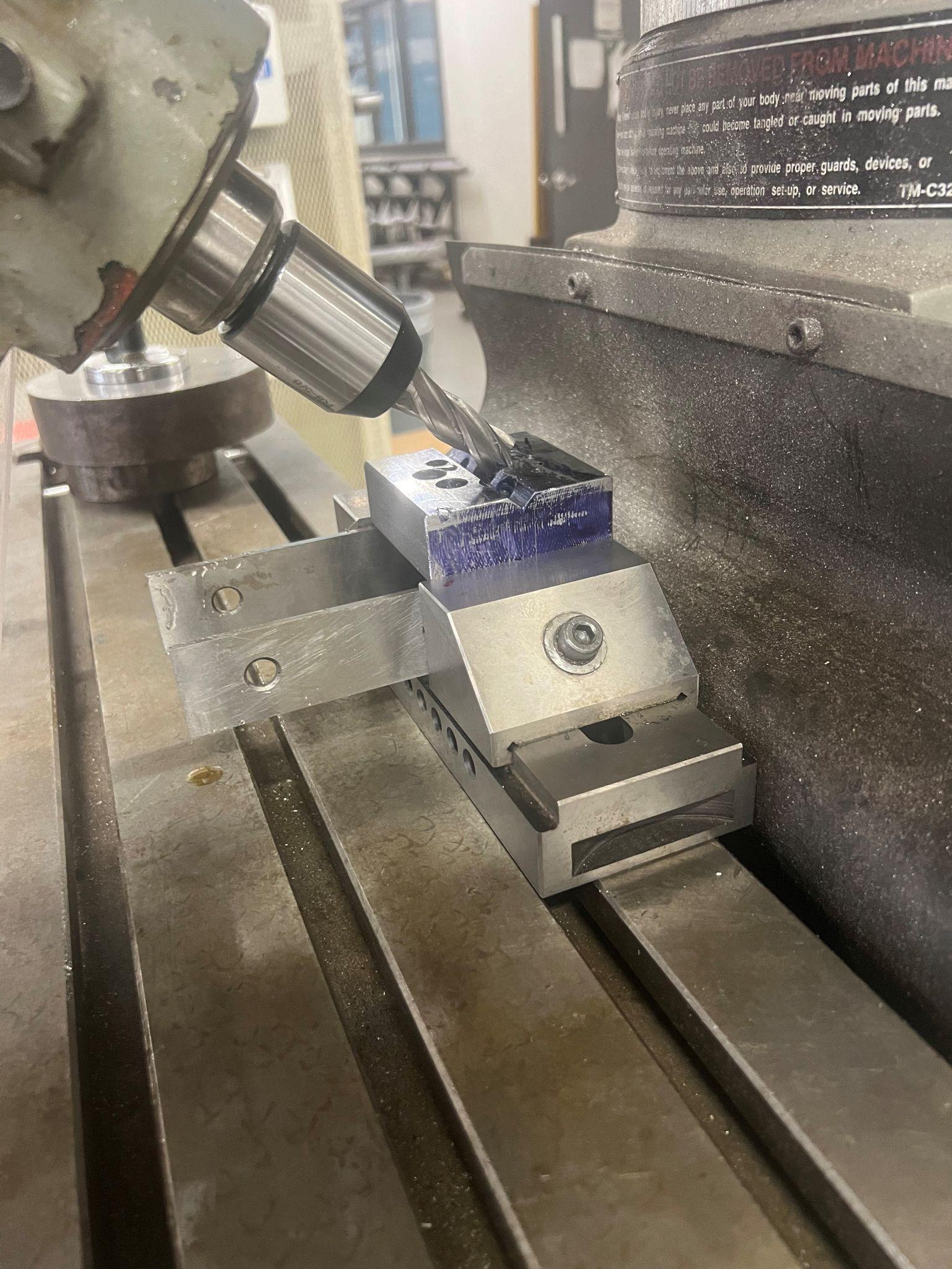
Spot, drill, and bore the holes before the groove is cut. Drilling into a slanted surface like the V groove will make the drill bend, and the hole will have a step in it. Trying to drill into a slanted surface is an advanced technique that requires cutting a flat spot into the slanted surface to provide a suitable area to start drilling.
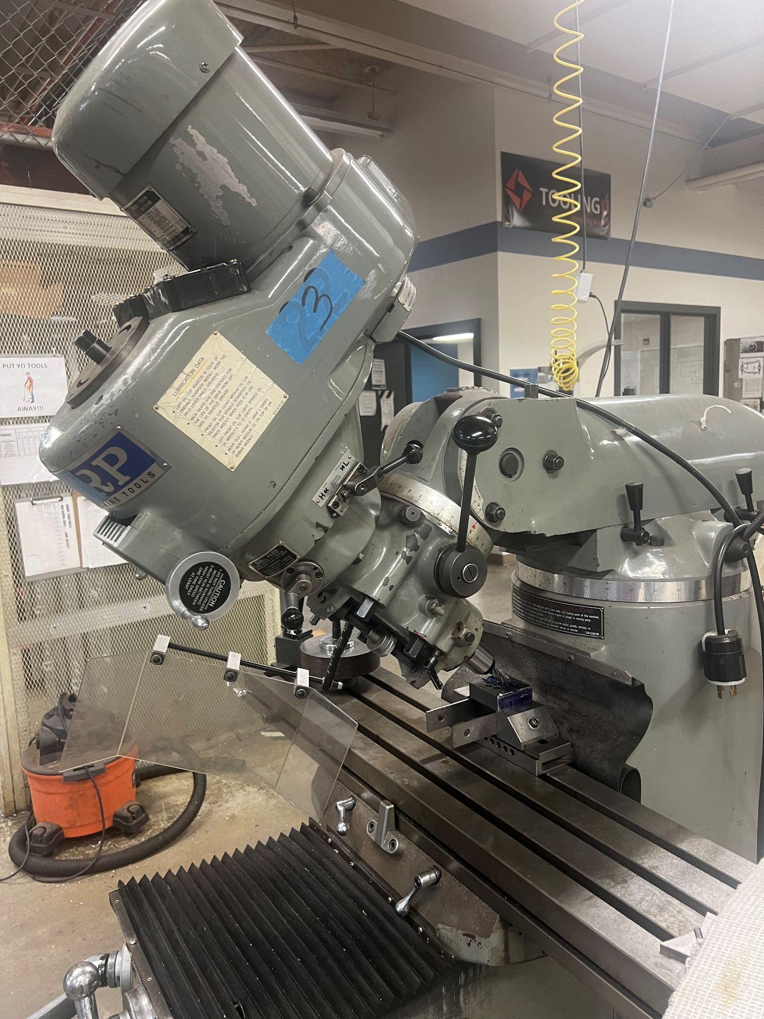
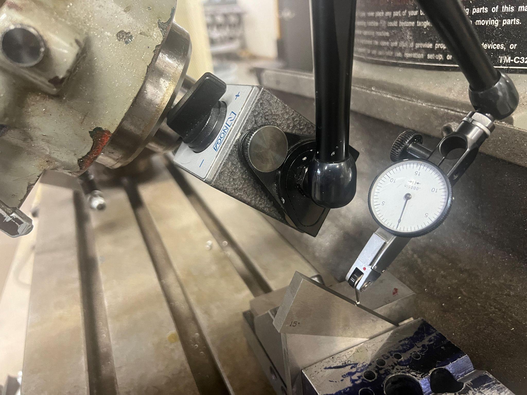
Cut the groove on the top of the part by nodding the head of the mill to 45 degrees. More information about this may be found in Chapter 11.
A rotary table on a manual mill could be used to rotate the part while cutting. This would create the pocket on the bottom of the part. Another option is to hold the part in a three jaw chuck on a lathe, and use a boring bar to make the pocket.
Author’s Tip
The pocket on the bottom of the part is to allow chips from tapping to exit the hole instead of being dragged up through the bench block.
At this point, a fixture will need to be built to hold the part using the holes that were created. This will allow the outside of the part to be turned down on the lathe.
Turning the square into a circle can be done on the lathe next.
- Knurl the outside of the round shape
- Turn the steps on the outside.
Find the Tools
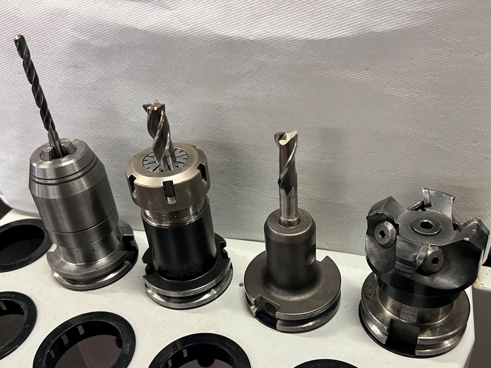
Once the planning is set, make a list of the tools needed and gather them. This is when changes may need to be made. If a tool is unavailable, the choice may be to buy one. But that usually takes time that you don’t have. Making or modifying a tool is a possibility, depending on your skills. Likely, the quickest solution is to substitute. For example, the bench block calls for a 6.5 mm drill. The holes are toleranced at -0/+.002. The 6.5 mm drill measures .256 inches. So, a letter F drill, which measures .257, will work and still be within tolerance.
Material
This specific project is made from mild steel, though a different material may be substituted if necessary. Recall that this information is typically found in the title block of the drawing.
Machines and Workholding
Identifying the machine to use and how to hold the part can happen together. For example, if a lathe is chosen as the machine, the part will likely be held in a three or four jaw chuck.
Every machine is different; they have their own capabilities. As explained earlier, this is the accuracy at which a machine will cut parts without any significant effort from the machinist. An example of influencing the process may be artificially controlling the temperature as a means to control material expansion. Heat can build up in the part, or it can be generated from the machine that is cutting the part. Expansion due to heat can make the part measure bigger than it really is when at room temperature. As discussed earlier, before starting a project, the machinist needs to consider machine capabilities and the ways in which they may need to control aspects of machine operation.
As machines differ, so do processes. Different processes will produce different finishes or surface qualities. Depending on the requirements of the part, an acceptable finish may be obtained from the initial material removal. A higher quality of finish can demand that a subsequent machining process is needed. The bench block project will adhere to the industry standards of a 32-micron finish or better. Please refer to Chapter 3 for further discussion of finishes.
One of the first concerns of a machinist should be to ask, “How tight is the tolerance?” Do I need to make a cut that is less than a sheet of paper thick? This would be within .003, spoken as three thousandths. Or, do I need to make a cut within an 1/8th, .125 of an inch? (Spoken as one hundred and twenty five thousandths.) The degree of precision will start to bring into focus the processes, and tools needed to make the parts.
Once a job plan is made, the machinist can begin making the part. To begin making the bench block, the following steps are necessary.
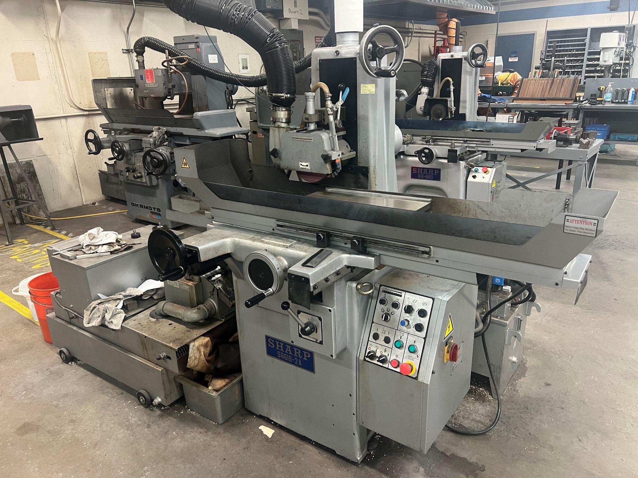
1. A surface grinder will remove the least amount of material. The part can be held with the magnetic chuck to accomplish this. Grind the large surfaces first. This will provide an accurate locating surface when holding the part in the vise to cut the smaller sides.
2. Using a face mill, or end mill, the short sides can be cut so that the opposite sides are parallel. This can be done in the mill while holding the part in a vise.
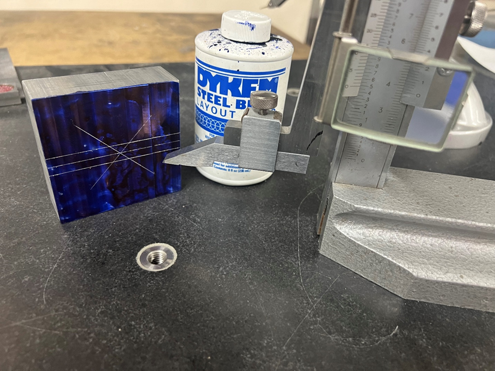
3. At this point, any scribe lines that were on the part are gone. Layout the center, the orientation of the V groove, and the width of the V groove before continuing. For more discussion on laying out a part, turn to Chapter 5.
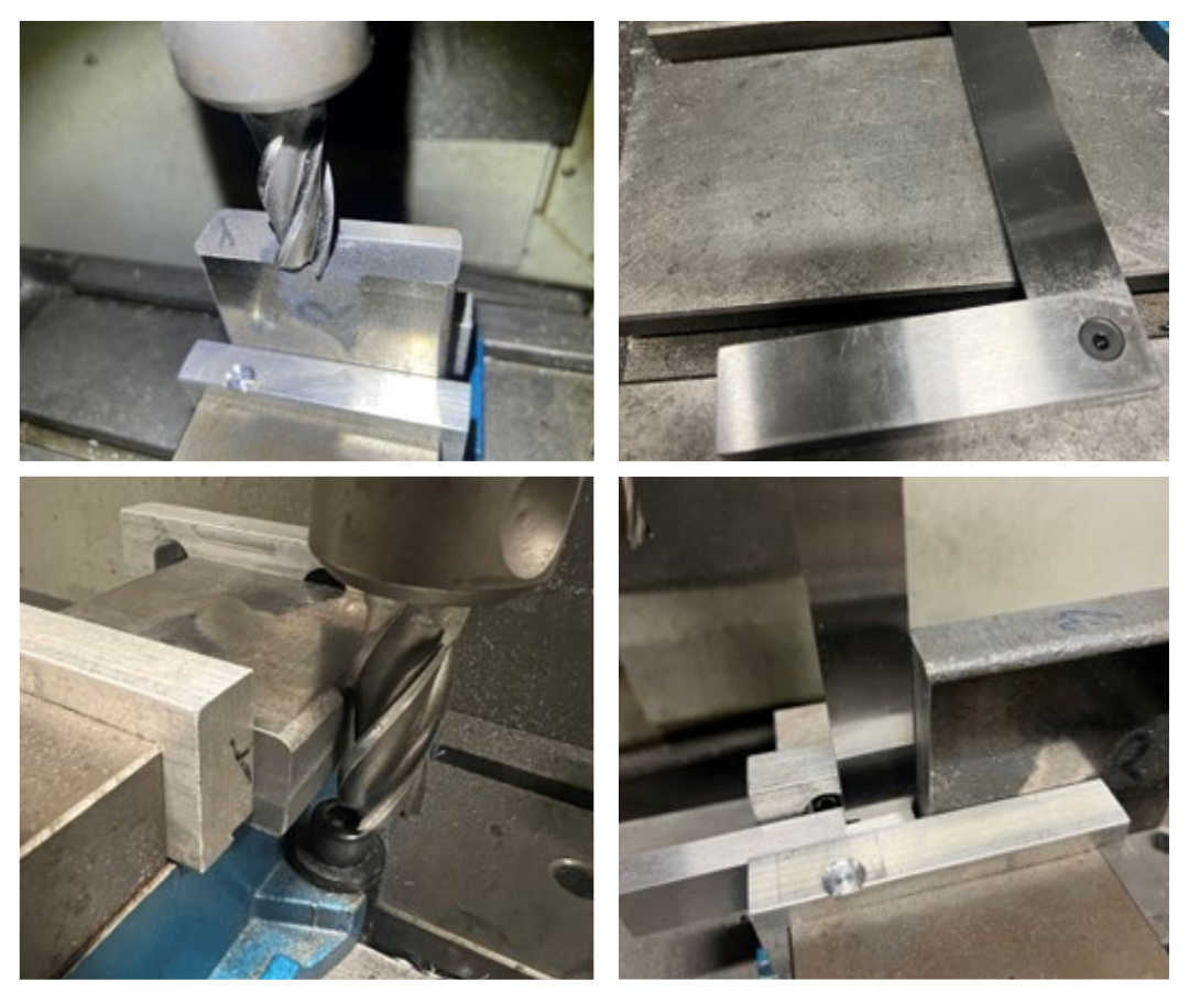
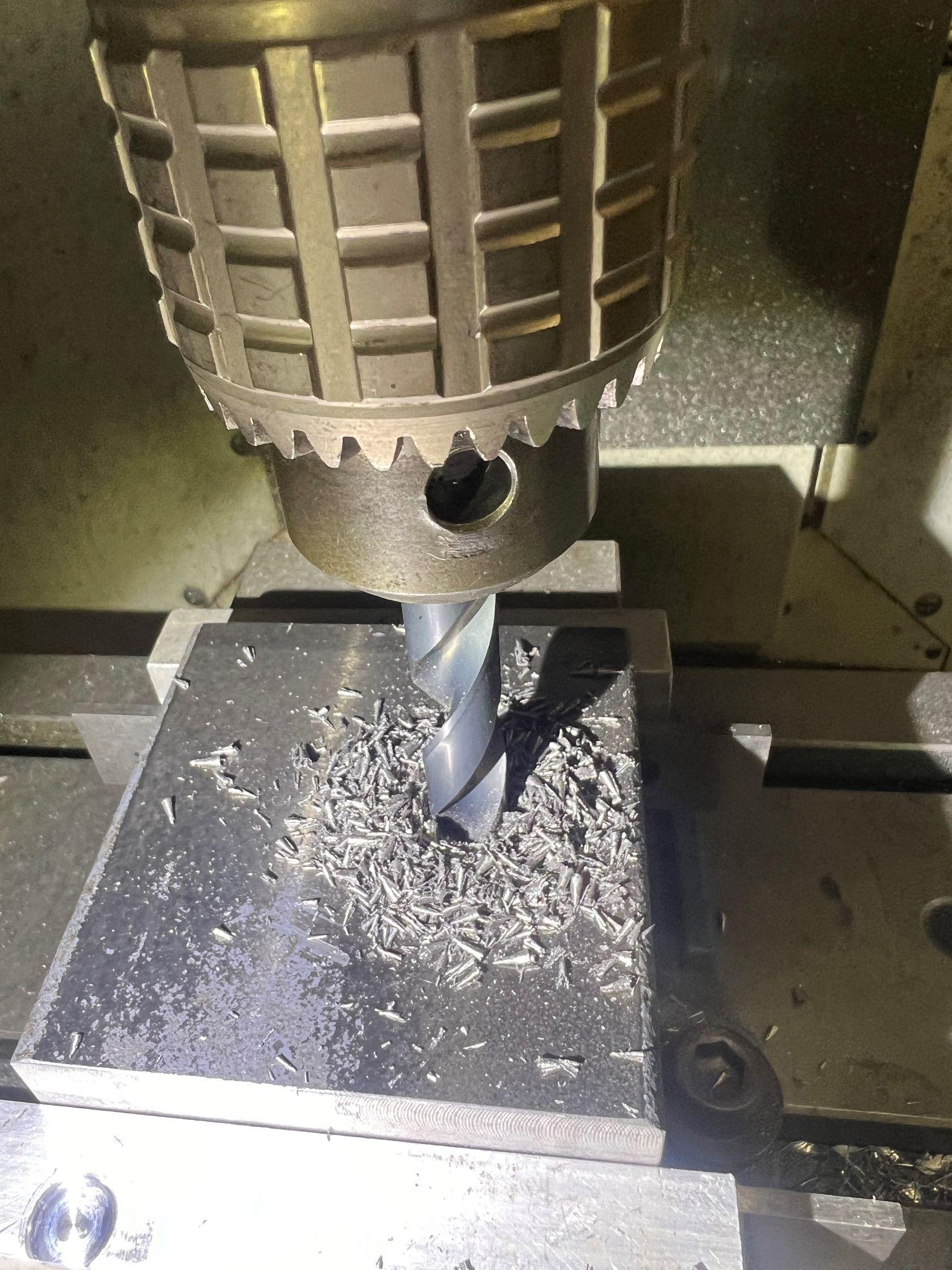
4. Put the part in the vise on the manual mill to drill the holes. Find the center of the part, and then move to the first hole location. To increase accuracy, and cut down on the work of locating each hole multiple times, complete each hole before moving to the next location. Locate the hole, spot drill, drill, and bore if needed, then move to the next hole.
Author’s Tip
If this job were done on a CNC machine, the sequence would be to spot drill all of the holes, then drill all of the holes, and finally bore the last four holes. This process takes advantage of the CNC machine’s ability to locate the holes repeatedly, and consistently. The time savings on this machine are in reducing tool changes.
5. Without taking the part out of the vise, drop the nod of the mill to 45 degrees and cut the V groove. Use the scribe lines to determine how much to cut.
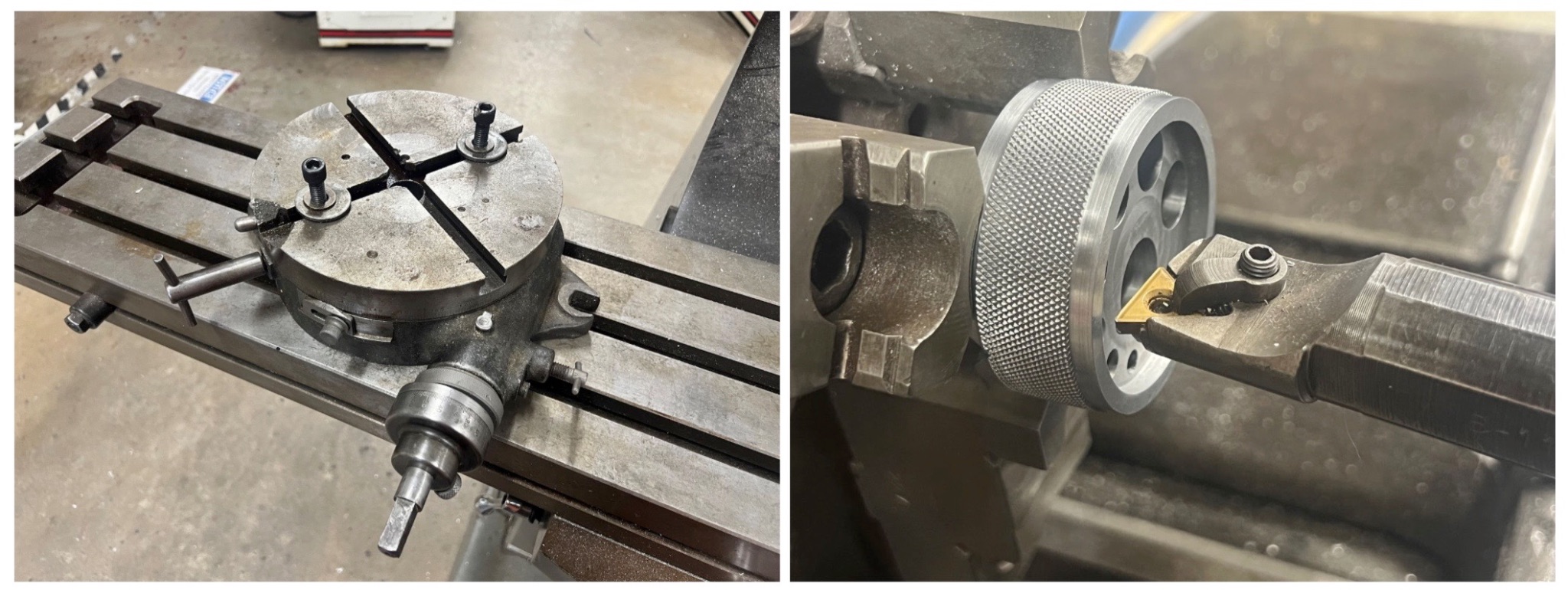
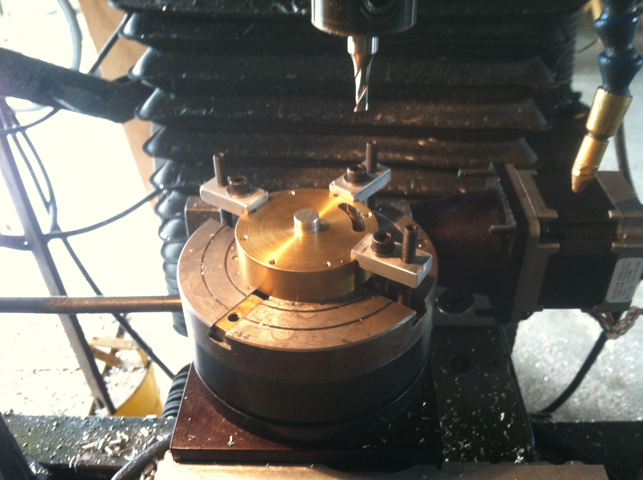
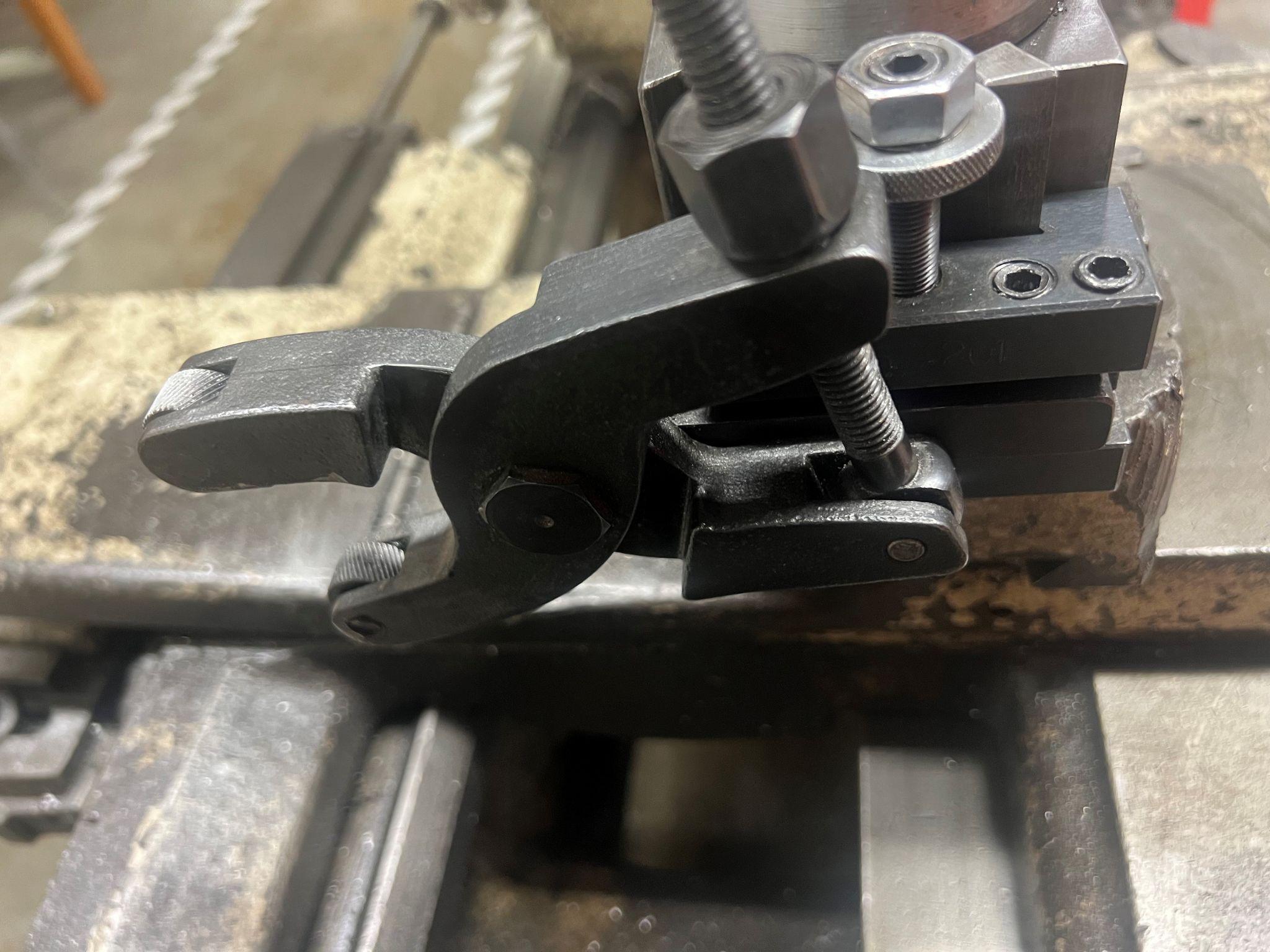
6. Now the part can be turned upside down and placed onto a rotary table. Locate the center of the part. Using an end mill, the pocket can be milled out by bringing the end mill down to the depth of the pocket and rotating the table. Start at the center, working the end mill out to create the final diameter of the pocket. The part, while it is still square, can be held similarly to the part in the picture below.
Author’s Tip
The mill will need to be trammed back in before continuing. Tramming realigns the spindle to a 90-degree (perpendicular) position to the table.
7. Now the outside of the part is ready to be turned into a circle. A fixture will need to be made to hold the block. A three cubic inch square piece of mild steel or aluminum will be adequate. The fixture will need to be squared up so that it can be held properly. After locating the center, use the coordinates of the two fixture holes from the drawing, drill, and tap the two holes. One hole will be for a ⅝-11 bolt that will hold the block to the fixture. The smaller hole will be for a ⅜-16 cap head shoulder bolt (CHSB). The head of the bolt will need to be turned down to .375, or removed. This bolt will keep the bench block from spinning on the fixture while being worked on.
8. Attach the bench block to the fixture using a standard bolt and the modified one from above. Hold the fixture in a four jaw chuck on a manual lathe. Leave some room between the bench block and the jaws for tool clearance while turning. Using the four jaw chuck will require the part to be dialed in. That means that it will rotate on the center of the part with a minimal amount of wobble. Turn the part down to the finish diameter of 2.25 inches with a right-hand turning tool.
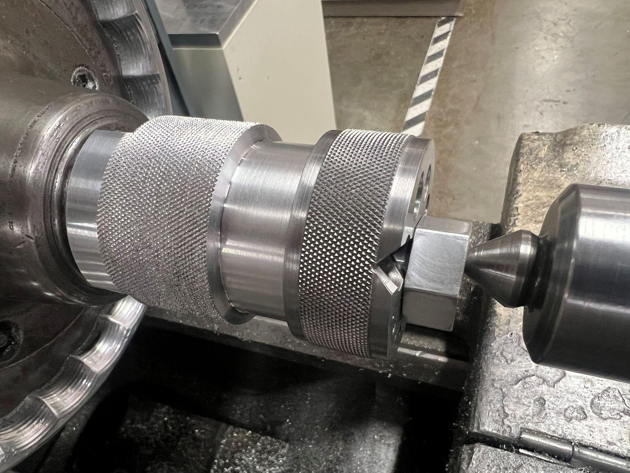
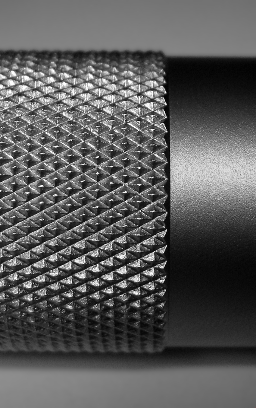
9. Leave the part and fixture in the four jaw chuck. Change from a turning tool to a knurling tool. The wheels on the knurling tool push the material around until the pattern forms. The wheels are available in different diameters. For this project, the .75 inch diameter wheels need to be used. A liberal amount of cutting oil should be applied while running to keep the pattern clean.
10. Knurling pushes the material around, and a small bulge may be present on the ends of the part. Put the turning tool back in the lathe and turn each side down .01 on the diameter, and .150 inches from each face. This will give the part a nice, crisp transition between the features.
11. The last step in any project is to clean it up. Remove any oil, chips, and most importantly, deburr the part. A small file is commonly used to remove sharp edges, and frayed material that is still connected to the part. Making the part finger-friendly shows you care about what you are doing. People who have been working in the industry will value your attention to detail. After all, it was your attention to detail that helped you put together a successful job plan.
Attributions
- Figure 6.22: Which side to start on by T Bacon, courtesy of Bates Technical College, for WA Open ProfTech, © SBCTC, CC BY 4.0
- Figure 6.23: Square up the block by T Bacon, courtesy of Bates Technical College, for WA Open ProfTech, © SBCTC, CC BY 4.0
- Figure 6.24: Bottom pocket options by T Bacon, courtesy of Bates Technical College, for WA Open ProfTech, © SBCTC, CC BY 4.0
- Figure 6.25: Lathe workholding by T Bacon, courtesy of Bates Technical College, for WA Open ProfTech, © SBCTC, CC BY 4.0
- Figure 6.26: Horizontal surface grinder by T Bacon, courtesy of Bates Technical College, for WA Open ProfTech, © SBCTC, CC BY 4.0
- Figure 6.27: Milling tools by T Bacon, courtesy of Bates Technical College, for WA Open ProfTech, © SBCTC, CC BY 4.0
- Figure 6.28: Layout by T Bacon, courtesy of Bates Technical College, for WA Open ProfTech, © SBCTC, CC BY 4.0
- Figure 6.29: Drilling by T Bacon, courtesy of Bates Technical College, for WA Open ProfTech, © SBCTC, CC BY 4.0
- Figure 6.30: Cutting the 45 degree groove by T Bacon, courtesy of Bates Technical College, for WA Open ProfTech, © SBCTC, CC BY 4.0
- Figure 6.31: Cutting the 45 degree groove 2 by T Bacon, courtesy of Bates Technical College, for WA Open ProfTech, © SBCTC, CC BY 4.0
- Figure 6.32: Cutting the 45 degree groove 3 by T Bacon, courtesy of Bates Technical College, for WA Open ProfTech, © SBCTC, CC BY 4.0
- Figure 6.33: IMG_5465 by Steamboat Ed is released under CC BY 4.0
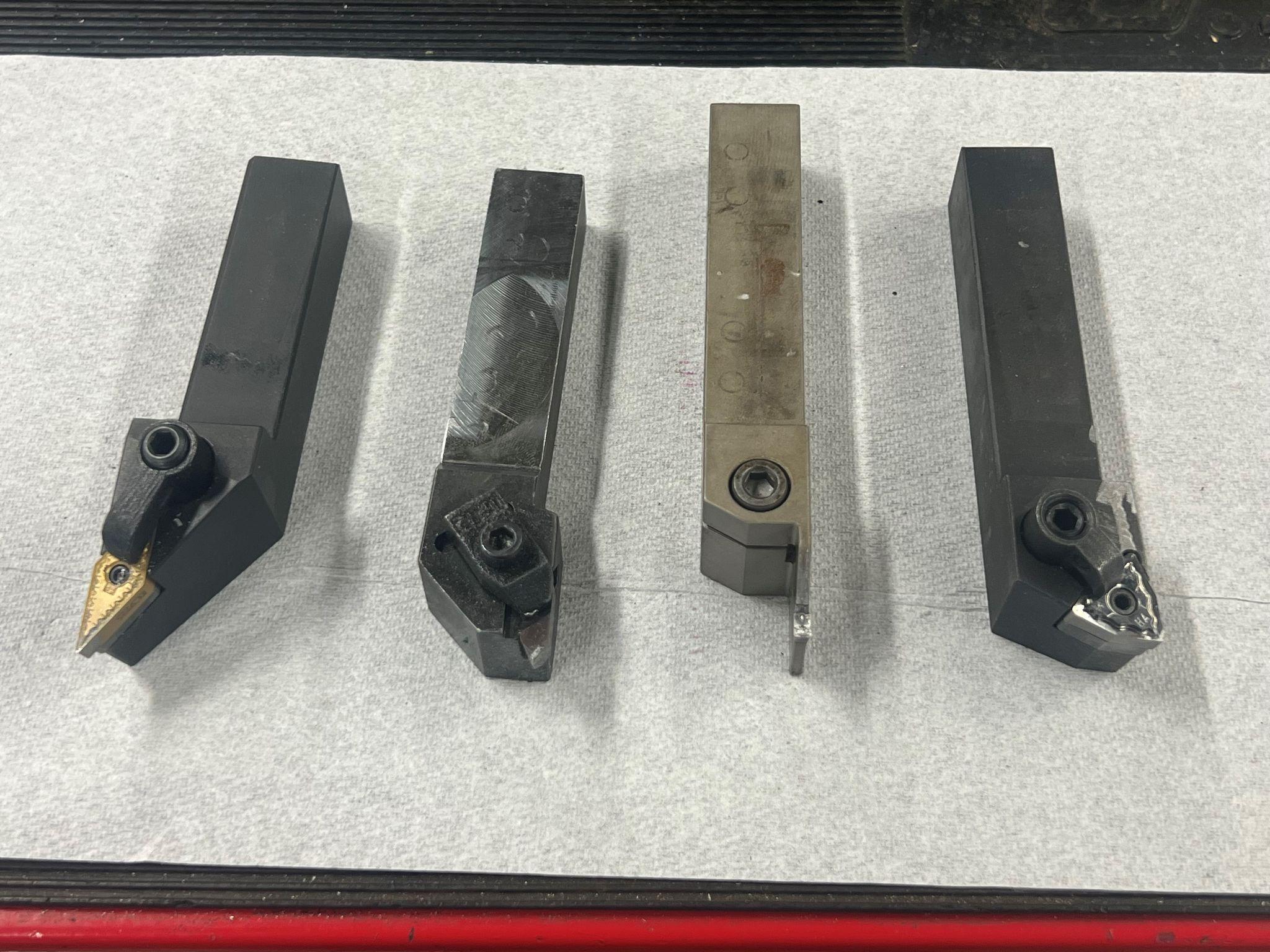
- Figure 6.34: Lathe tools by T Bacon, courtesy of Bates Technical College, for WA Open ProfTech, © SBCTC, CC BY 4.0
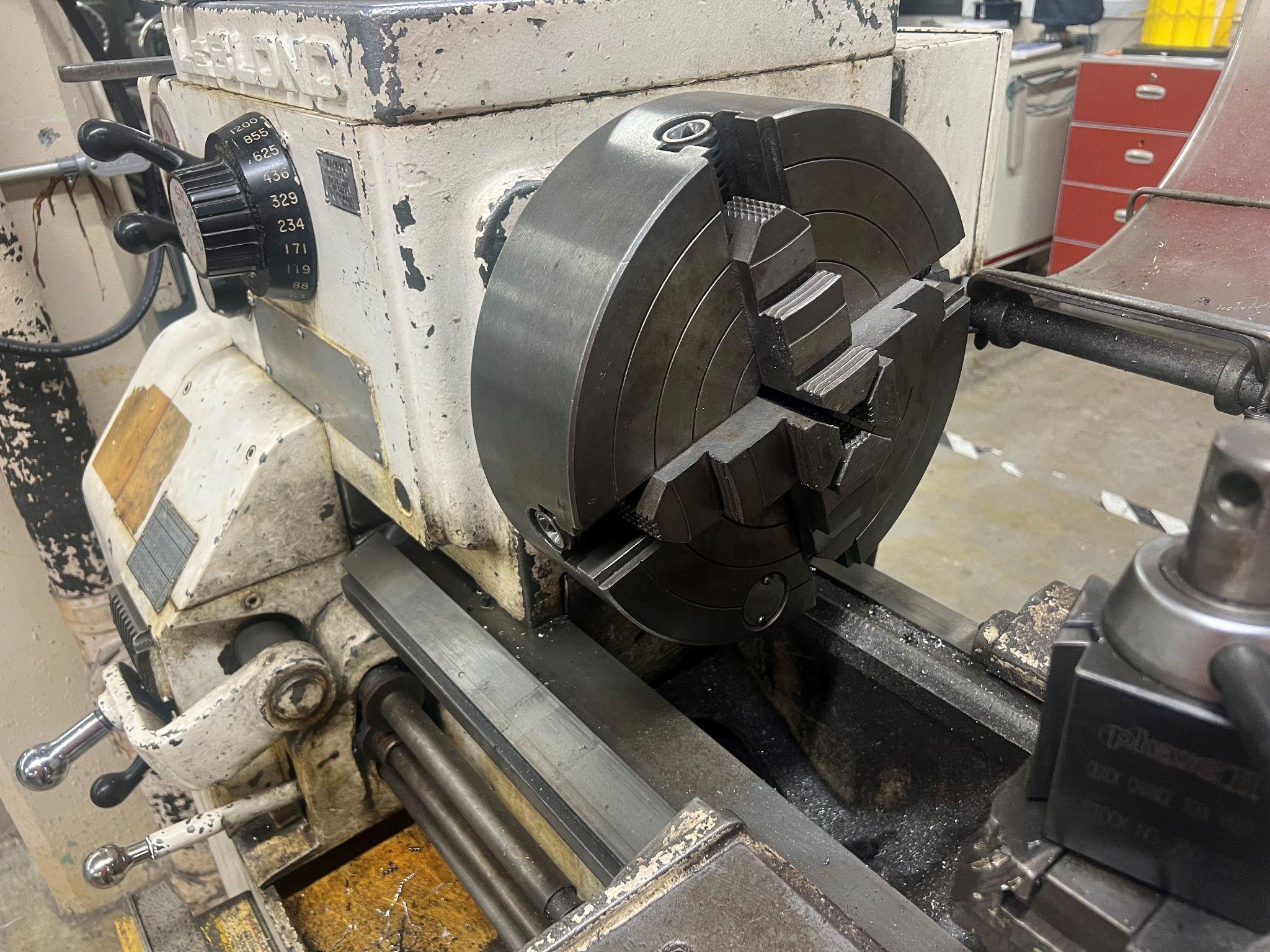
- Figure 6.35: Four jaw chuck by T Bacon, courtesy of Bates Technical College, for WA Open ProfTech, © SBCTC, CC BY 4.0
- Figure 6.36: Knurling tool by T Bacon, courtesy of Bates Technical College, for WA Open ProfTech, © SBCTC, CC BY 4.0
- Figure 6.37: Knurling Closeup by Contributor is released under CC BY-SA 2.5
Non Conforming Material. This identification is used on setup parts to clearly show that the material einging used is not intended for the customer.
On a manual mill, the nod is when the head is tiped forward, or back along the Y axis.
A rotary table is a mechanical device designed to rotate a workpiece around a vertical axis. A vise can be mounted on top of the table to allow for circular, and angled cuts.
When the head of a manual mill is set up perpendicularly to both the X, and Y axis.
Cap Head Shoulder Bolt. This is a common description of bolts used in assemblies.
