8.4 Workholding
Micky R. Jennings
Workholding devices on a drill press are designed to securely hold material for hole making operations. They need to be simple, quick, and easy to use. The most common workholding solutions on a drill press are vises and clamps. These solutions come in many different styles but perform the same function of holding the work.
Drill press vise
A drill press vise is a common workholding device on a drill press. They come in many shapes and sizes, but they share some basic features. The drill vise will have a base that is machined on the bottom so it sits flat on the drill press table. This is to assure that parts will sit flat in the vise for stability and accuracy, and to help establish the primary datum. The top side will have two jaws; a solid jaw and a movable jaw. The solid jaw doesn’t move and is made square to the top surfaces of the vise, creating the secondary datum. The movable jaw is attached to a mechanism that the operator adjusts to put pressure on the part holding it against the solid jaw. The base of the vise will also have some way to attach the vise to the table for heavier cutting operations.
Screw-actuated vise
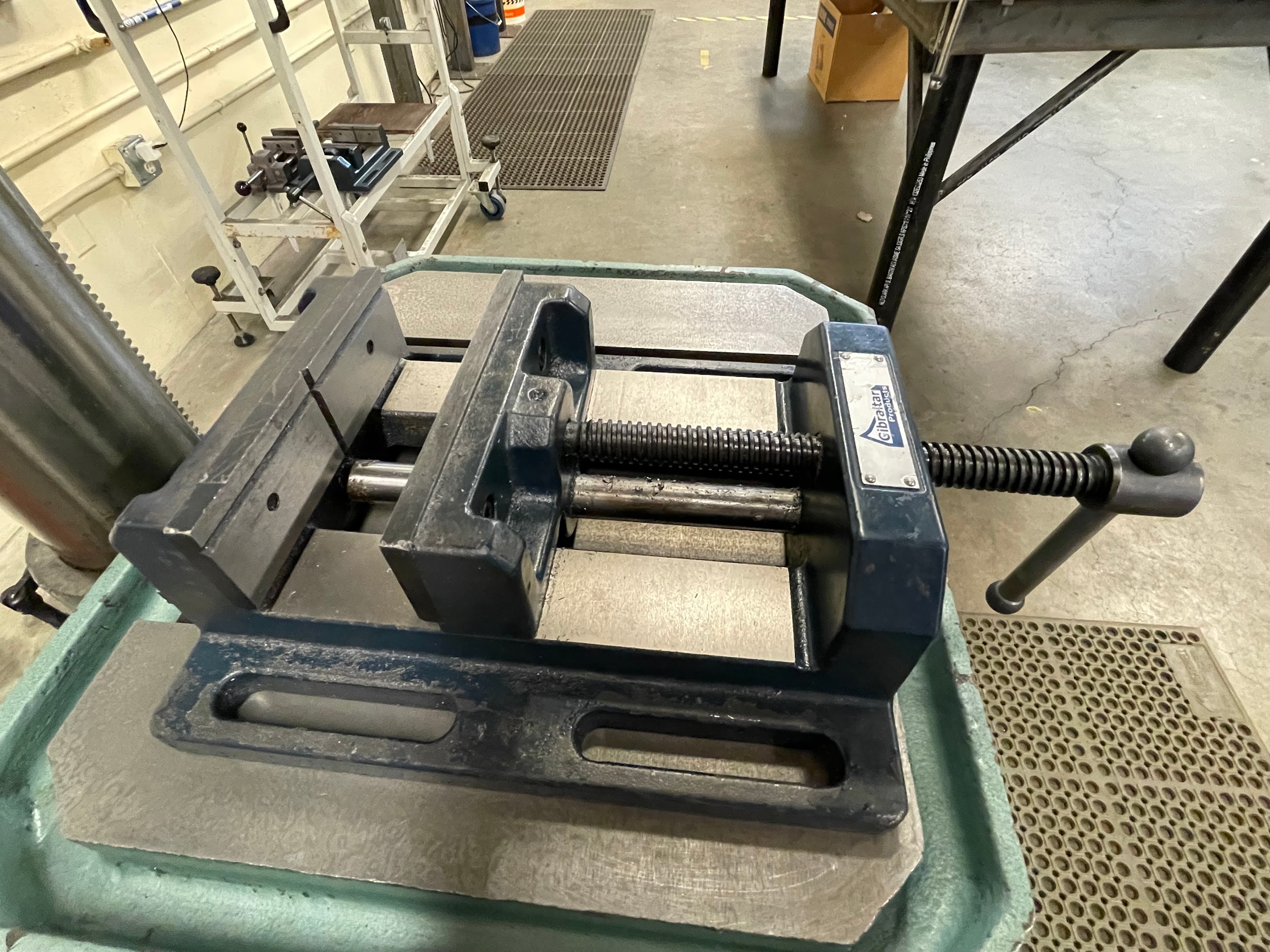

The screw-actuated vise utilizes a basic unified screw thread, an acme thread or a square thread, to transmit the clamping force needed for workholding. Entry level vises with lower clamping force will be equipped with a 60-degree unified thread, while vises intended for heavier duty clamping will use increasingly flatter threads because of their strength.
Cam actuated vise
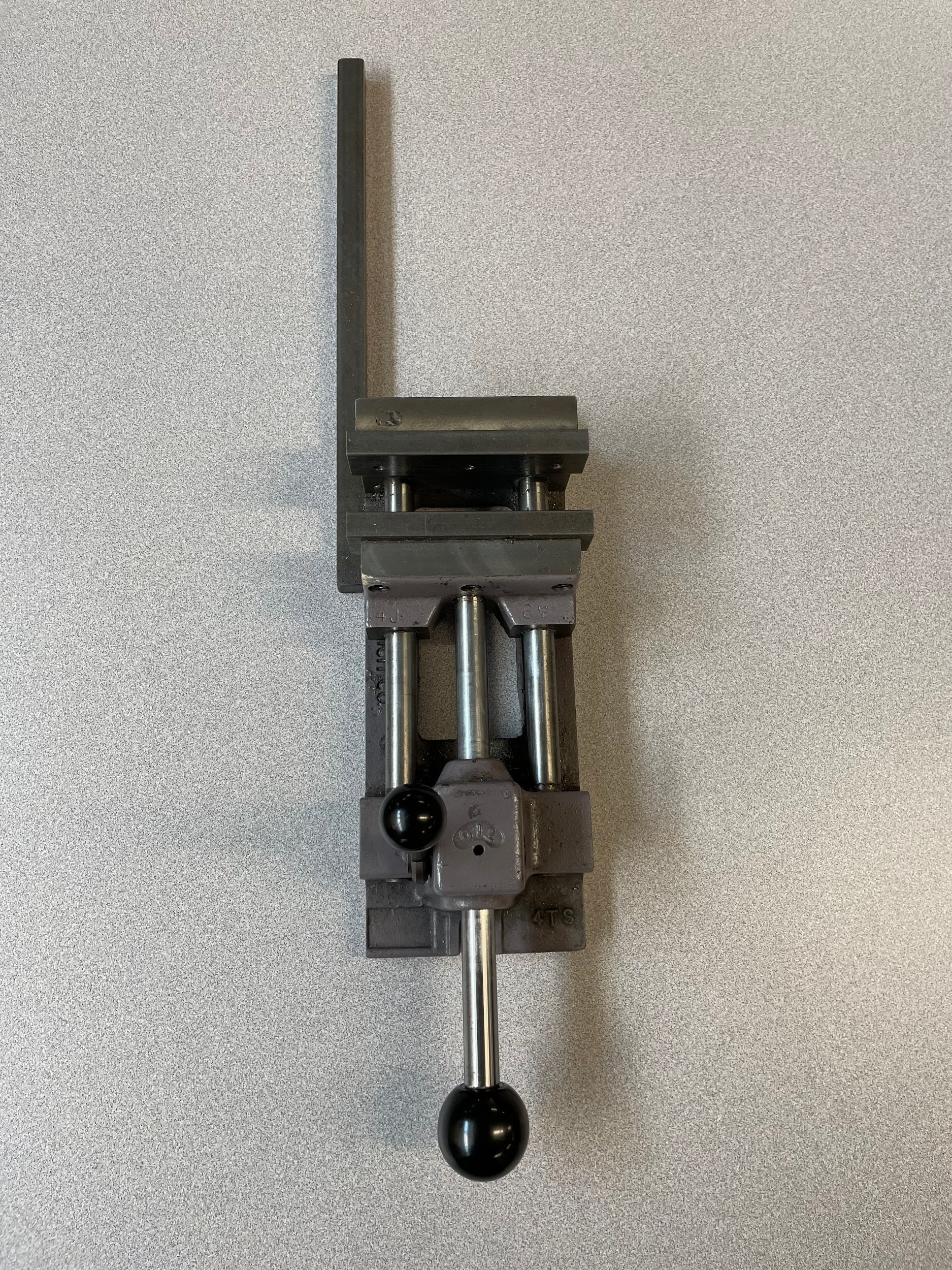
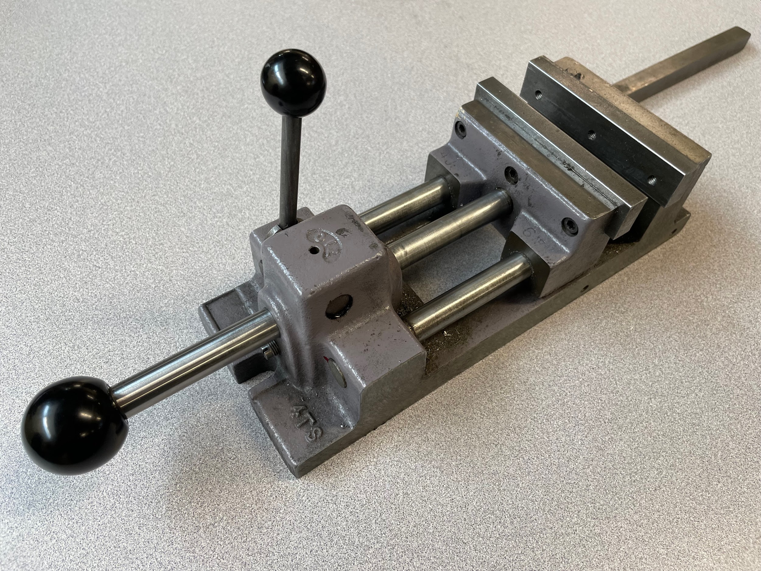

A cam actuated vise uses a rod and a friction lever to apply gripping force to the jaws. When in action, the user manually pushes the movable jaw up into the part by putting pressure on the knob at the end of the rod. Once the movable jaw is snug, the lever is pushed downward, and the friction of the camming mechanism increases the pressure on the part, giving added grip strength.
Parallels
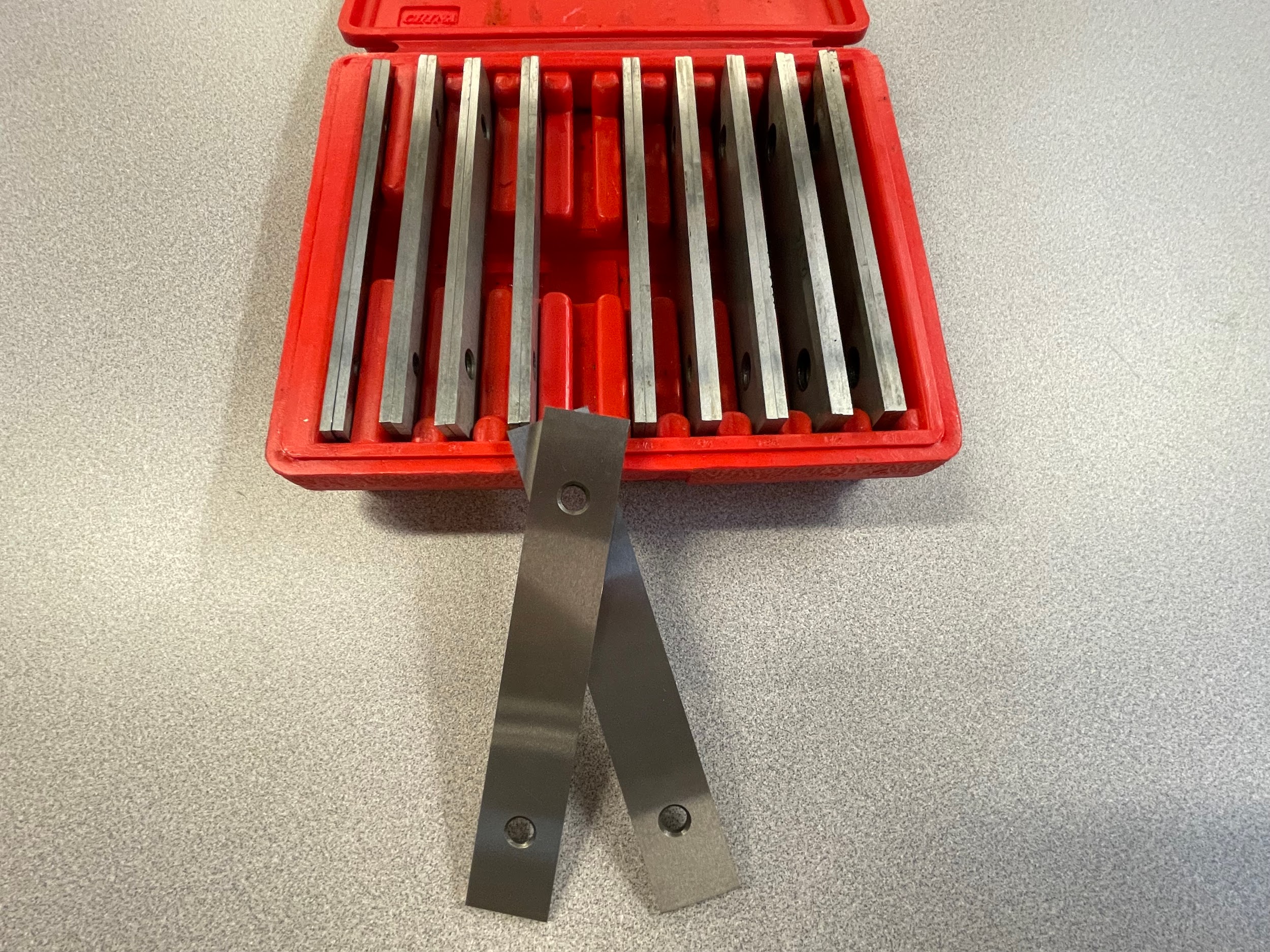
Parallels are used on a drill press in order to raise parts off the table or off the top surfaces of the vise. They are called parallels because the advertised surfaces are ground flat and parallel to one another. They generally come in pairs, and multiple pairs come in a set. For vise use, ⅛” thick parallels are the modern standard of the industry, with a set containing ½” to 1-⅝” heights in ⅛” increments. With parallels used to raise parts off the table, they are usually thicker, ½” or more, so they stand up on their own, and have less incremental change in height.
Clamp
Clamps are a common workholding device on a drill press and they come in many shapes and styles. Clamps are used to hold a workpiece firmly on a table. Tee slots allow clamping devices to grip the table and better secure parts while working. A simple drill press has a table that accommodates clamping devices.
C-clamp
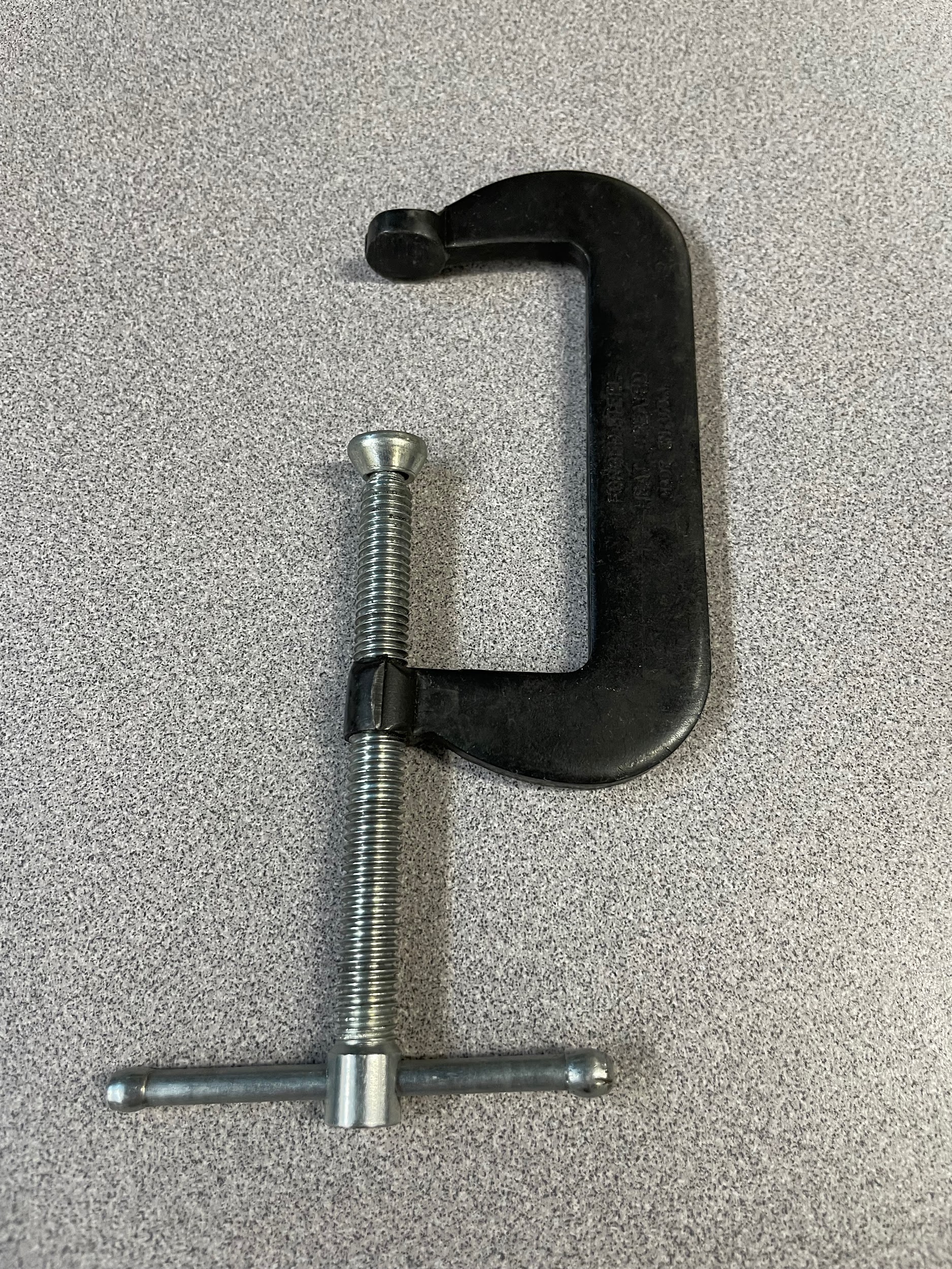
C-clamps, also discussed in Chapter 5, are familiar to a lot of people because they are used in many industries. The main frame of the clamp is shaped like the letter “C”. On one end of the clamp is a pad for gripping, on the other is a screw for adjusting and tightening the clamp. At the end of the screw is another pad for gripping. On a drill press C-clamps can be used to secure parts directly to the table.
Cantilever clamp
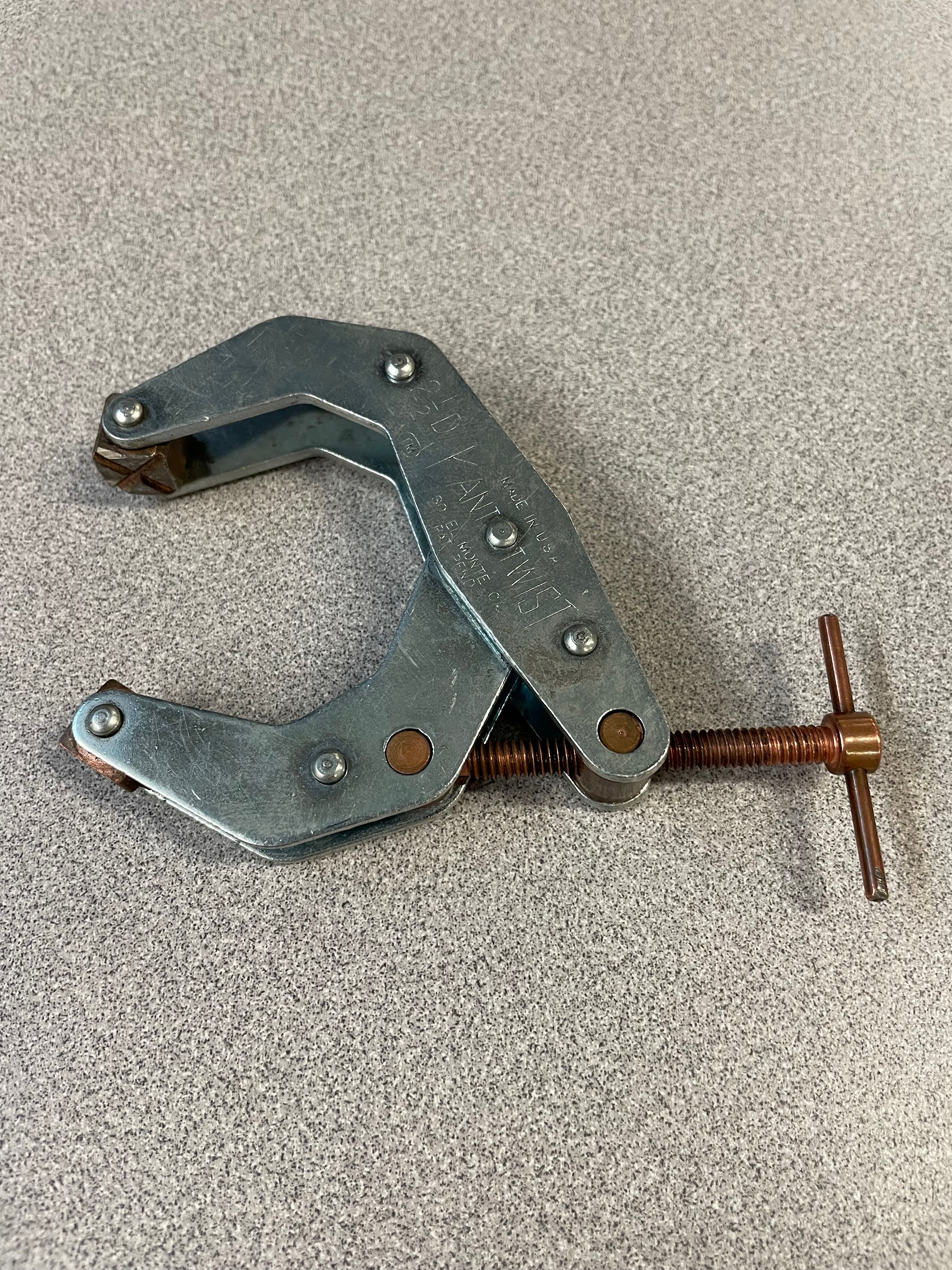
A cantilever clamp is similar to a C-clamp in its use, clamping parts to the table of a drill press, but its construction is different. A cantilever clamp uses a scissor motion in conjunction with screw pressure for the gripping force. The gripping pads of this style clamp rotate and conform to uneven parts. These clamps are often better suited to machine work because the design affords extra clearance and are easier to work around.
Fixture clamps
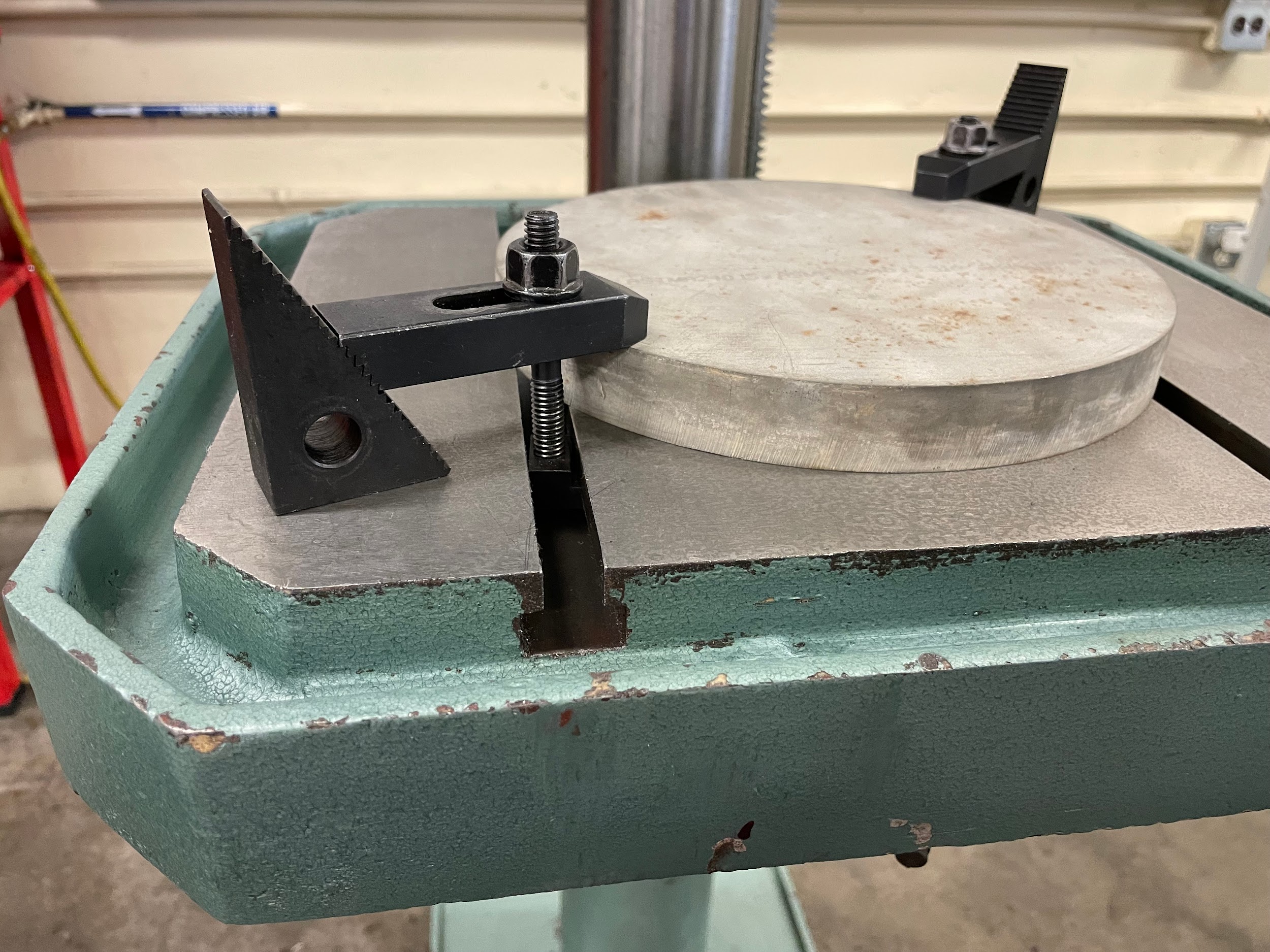
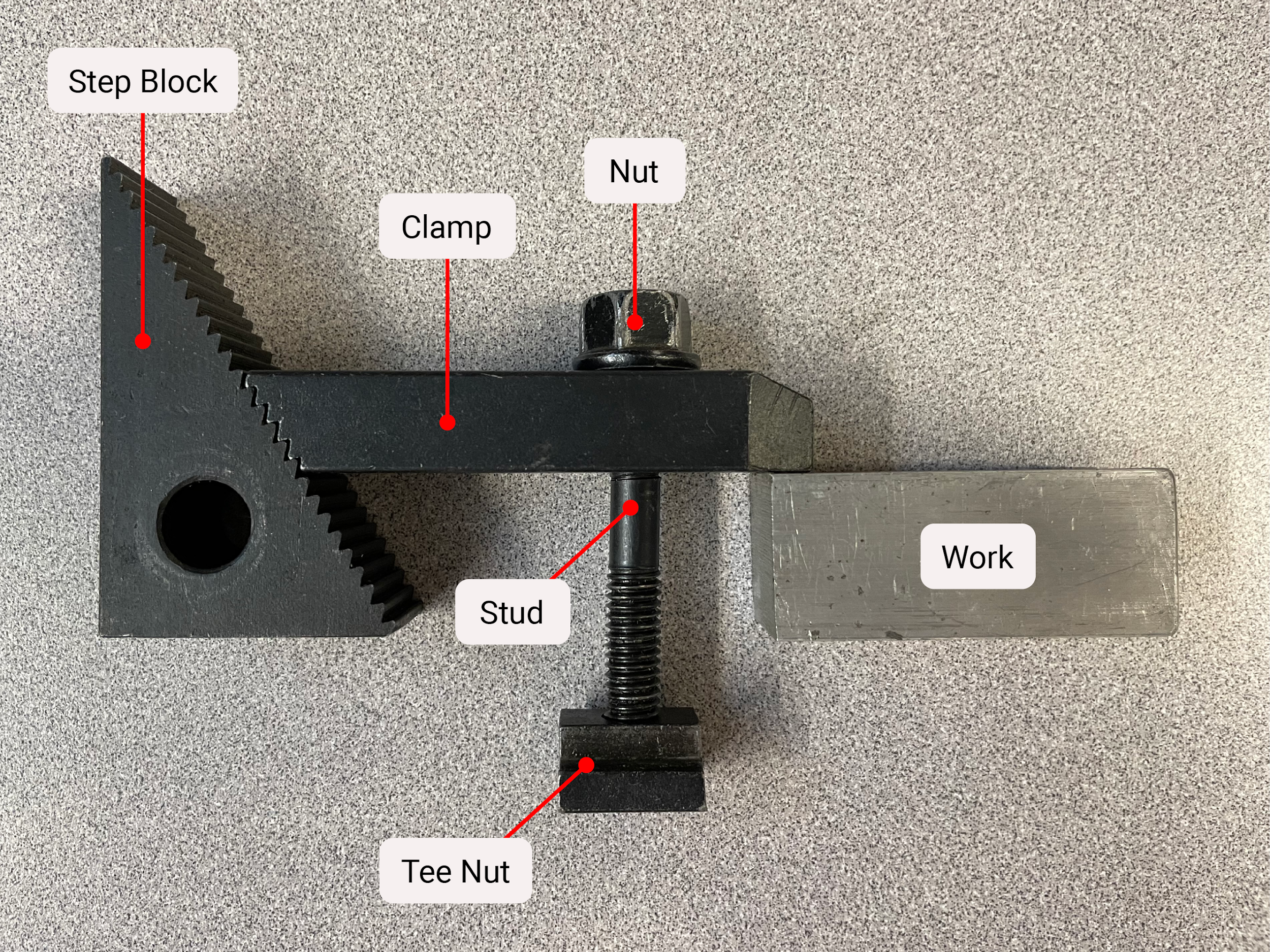
Fixture clamps generally come as a clamping kit. The kit will contain T-nuts, studs, regular nuts, risers, extensions, and the clamps themselves. When in use, the operator will select the components needed to clamp the part to the drill press table. The end setup will have a clamp spanning a short gap between the part and the riser. In the middle of the gap will be the stud, the T-nut in the table, and the regular nut tightened on top of the clamp. The clamp must be level or slightly lower on the part side. This makes sure the end can grip correctly on the part. The bolt must also be as close to the part as possible. With the bolt close to the part, a greater percentage of force is put into the part rather than the riser. If the bolt is closer to the riser, the majority of holding force is put into the riser and there is potential for the part to come loose inadvertently.
Attributions
- Figure 8.26: 6″ Drill press vise by Micky R. Jennings, courtesy of Wenatchee Valley College, for WA Open ProfTech, © SBCTC, CC BY 4.0
- Video 8.2: Micky R. Jennings, courtesy of Wenatchee Valley College, for WA Open ProfTech, © SBCTC, CC BY 4.0
- Figure 8.27: Cam lock vise by Micky R. Jennings, courtesy of Wenatchee Valley College, for WA Open ProfTech, © SBCTC, CC BY 4.0
- Figure 8.28: Cam lock vise 2 by Micky R. Jennings, courtesy of Wenatchee Valley College, for WA Open ProfTech, © SBCTC, CC BY 4.0
- Video 8.3: Micky R. Jennings, courtesy of Wenatchee Valley College, for WA Open ProfTech, © SBCTC, CC BY 4.0
- Figure 8.29: Parallels by Micky R. Jennings, courtesy of Wenatchee Valley College, for WA Open ProfTech, © SBCTC, CC BY 4.0
- Figure 8.30: C-Clamp by Micky R. Jennings, courtesy of Wenatchee Valley College, for WA Open ProfTech, © SBCTC, CC BY 4.0
- Figure 8.31: Cantilever clamp by Micky R. Jennings, courtesy of Wenatchee Valley College, for WA Open ProfTech, © SBCTC, CC BY 4.0
- Figure 8.32: Fixture clamps in use by Micky R. Jennings, courtesy of Wenatchee Valley College, for WA Open ProfTech, © SBCTC, CC BY 4.0
- Figure 8.33: Fixture clamp use with the stud closest to the material by Micky R. Jennings, courtesy of Wenatchee Valley College, for WA Open ProfTech, © SBCTC, CC BY 4.0
A simple work holding device used on a drill press.
A device used to accurately elevate work from precision surfaces.
A device used to secure work in a machine shop.
