59 CAC-A Equipment and Setup
Stephanie Oostman
Components
The information included in this section is generalized, and you should check with the operating manual and/or manufacture of your specific equipment on set up procedures, limitations, and safety considerations.
In section 13.2.1 Basics of the Process we read what CAC-A does, and a few notes on specifications on the equipment. Most welding machines that are capable of SMAW can also be used to perform CAC-A with a few additional pieces of equipment. To set up a welding machine for manual CAC-A you will need the following:
- A constant current (CC) welding machine capable of at least 28V output.
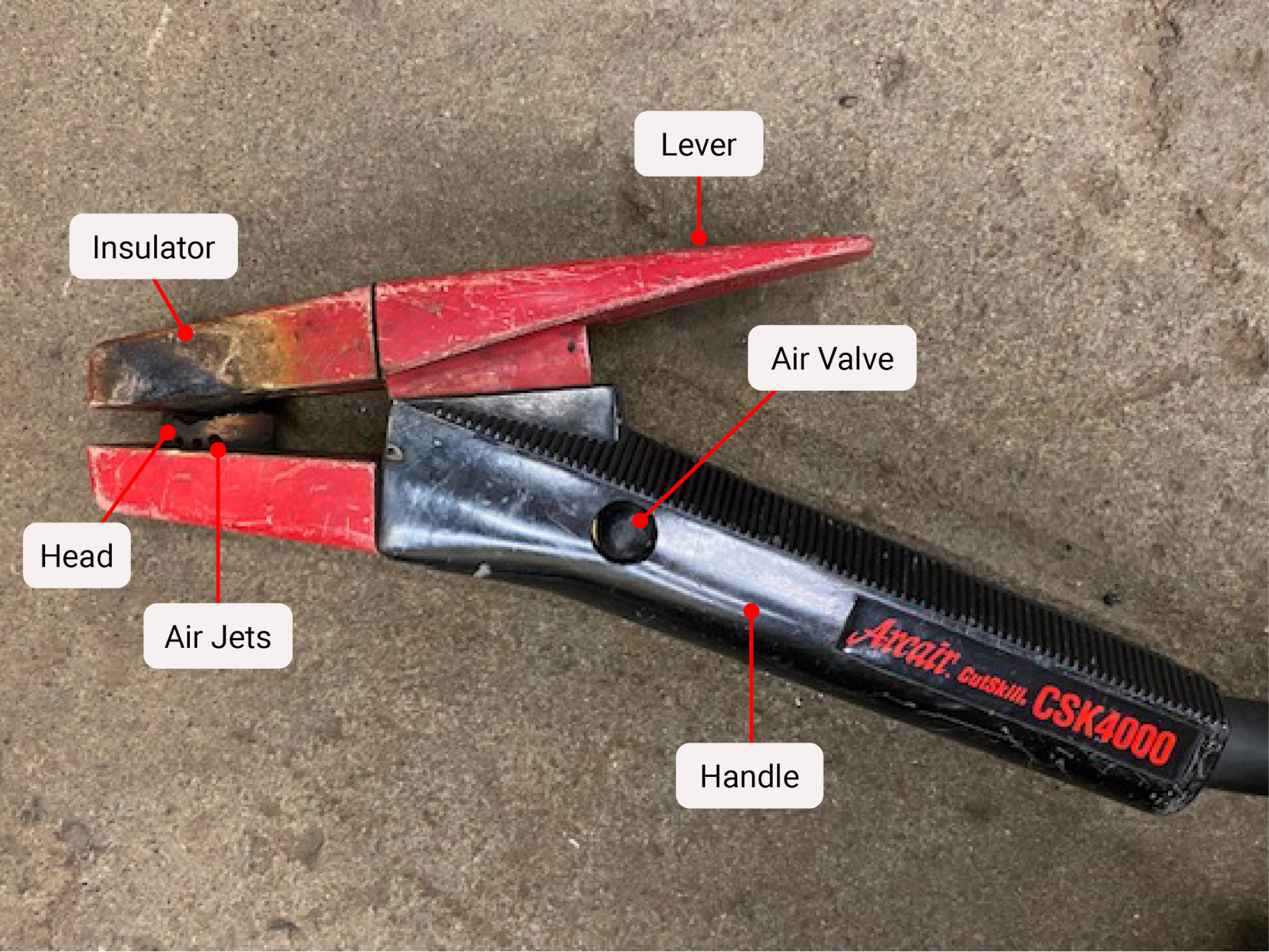
- A CAC-A Electrode holder. See image above
- A ground clamp.
- Carbon arc electrodes capable of the polarity you need.
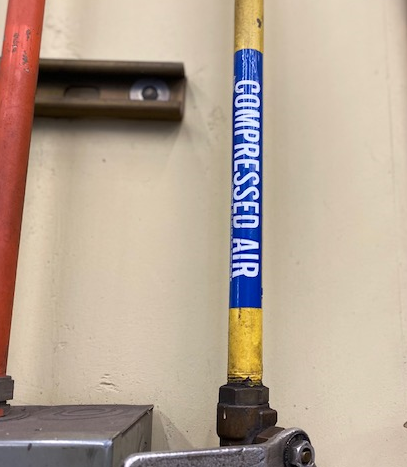
- compressed air that can be supplied at at least 80-100 psi.
- Air Hose for compressed air.
The power source can be either AC or DCEP, however the carbon arc cutting process requires higher output than some welding machines produce, making them an ineffective choice for this process. Running a machine at the higher output needed for CAC may cause the machine to over extend its duty cycle unless the machine is a heavy industrial type capable of 100% duty cycle, to avoid overloading your welding machine take breaks and consult the manufacturer for the machine’s duty cycle.
The electrode type and diameter, and the material to be cut, may also impact which polarity to select. Minimum electrode diameters, polarity, amperage and air pressure settings will all be dictated by what the material is and how thick. This is no different than most welding procedures. A ¼” electrode on DCEP has a range of 200-400 amps for example, and can be used to cut carbon steel, stainless, copper and nickel alloys, aluminum and cast iron.
Air supplied should be 80-100 psi nominal. While you can use higher than 100 psi, it does not make the removal of molten metal more effective. The air line needs to have at least an inner diameter of ⅜”, and the air compressor must meet the needed capacity to adequately produce a clean effective cut. For lighter duty work, these recommendations can vary with air pressure as low as 40 psi and an airline inner diameter of ¼”. If the air pressure is not sufficient, the operator will not be able to produce a smooth, uniform cut. This can also happen if the diameter of the air hose used is too small, as it will create a constriction of air flow to the electrode holder.
Note: Oxygen should never be used in place of compressed air in the CAC-A process.
The modern day CAC-A torch is designed to bring both the electrical cutting power of the process together with the blasting power for compressed air.
Refer to the pictures in this section. Both the upper and lower jaws are insulted and the lower jaw has a head with holes to allow compressed air through. The head can be rotated allowing for different angles or positions and both jaws only have one groove that can accept multitude of electrode sizes. Not all torches are created equal. Just like different electrodes are designed for different amperages, torches are also rated for amperage. Using a lower amperage rated holder may be dangerous or cause damage to the holder and other equipment.
Setting up the System
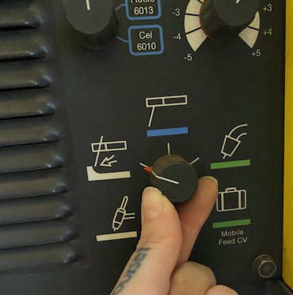
Look at your welding machine, it may have a setting for CAC-A already available.
If that’s true, select that program on the machine.
For carbon steel applications, connect the ground clamp to the negative terminal of a CAC-A capable welder, and the end of the CAC-A electrode holder to the positive terminal.
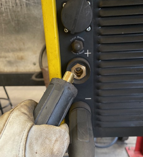
This is now set up for DCEP (reverse polarity). As mentioned previously in this text, DCEN should not be used in the carbon arc cutting process.
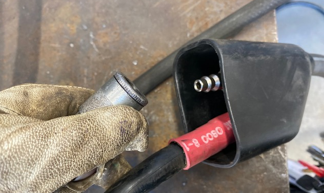
Next connect compressed air to the CAC-A via an air hose with at least an inside diameter of ⅜” The air pressure will need to reach 40-80 psi for general applications, but may require upwards of 100 psi for heavier duty needs.
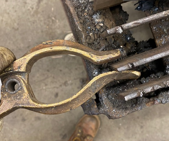
Don’t forget to connect your ground clamp to your cutting table to complete the electrical circuit.
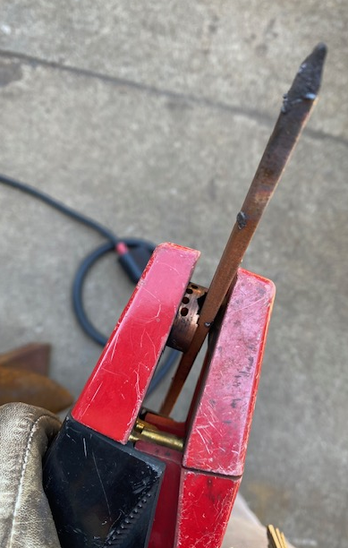
Next select a carbon arc rod. When placing the electrode in the holder, the end should be within 6” of the air holes, but not closer than 2” to prevent damage to the equipment.
The holder must be held so that the air holes are positioned on the bottom in order for the air to effectively blow the molten dross away from the area being worked.
Next set the voltage output on your welding machine.
Electrodes
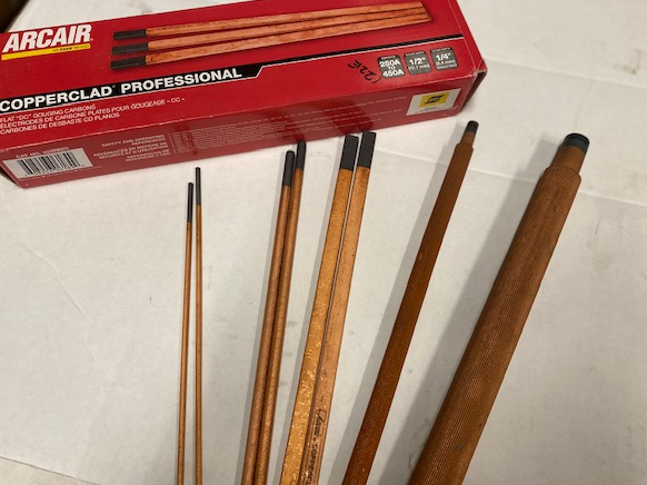
Electrodes may be copper coated or plain graphite. The copper coating on the electrodes keep the electrode from overheating, and increases its conductivity and arc stability when using higher amperages. It can also make the electrode slightly more durable. Both types of carbon arc rods are fragile, and should not be left in the rain or out in moisture. If you are using alternating current (AC), then a special electrode type must be chosen. These AC electrodes contain other elemental additives which aid in their stability.
Carbon electrodes come in a multitude of sizes, each rated to withstand more or less amperage, and come in round, rectangular or diamond shaped.
Some Electrodes can be joined together to reduce waste, and also to increase productivity in robotic and semi-automatic operations.
Attributions
- Figure 13.1: CAC-A Electrode Holder by Stephanie Oostman, for WA Open ProfTech, © SBCTC, CC BY 4.0
- Figure 13.2: Compressed Air Line by Stephanie Oostman, for WA Open ProfTech, © SBCTC, CC BY 4.0
- Figure 13.3: A carbon arc electrode in the electrode holder by Stephanie Oostman, for WA Open ProfTech, © SBCTC, CC BY 4.0
- Figure 13.4: CAC-A setting selection by Stephanie Oostman, for WA Open ProfTech, © SBCTC, CC BY 4.0
- Figure 13.5: The electrode holder is connected to the positive by Stephanie Oostman, for WA Open ProfTech, © SBCTC, CC BY 4.0
- Figure 13.6: Air hose connection into the CAC-A electrode holder by Stephanie Oostman, for WA Open ProfTech, © SBCTC, CC BY 4.0
- Figure 13.7: Connect the group clamp by Stephanie Oostman, for WA Open ProfTech, © SBCTC, CC BY 4.0
- Figure 13.8: Carbon arc electrodes by Stephanie Oostman, for WA Open ProfTech, © SBCTC, CC BY 4.0
No fabrication shop would function without power tools and shop equipment. The tools a shop has essentially determine the type and amount of work it can do. We are loosely defining power tools here as tools that require electricity to function and that can be held or moved by hand. Shop equipment is also powered by electricity, but is generally too large to hold or move by hand, and so these items tend to be stationary.
Cutting Tools
Cutting tools are used to prepare metal stock by reducing it to the necessary size, shape, and length. Handheld power tools for cutting metal include angle grinders, portable bandsaws, circular saws, and jigsaws. Shop equipment for cutting material includes bandsaws, cut-off saws, and metal shears.
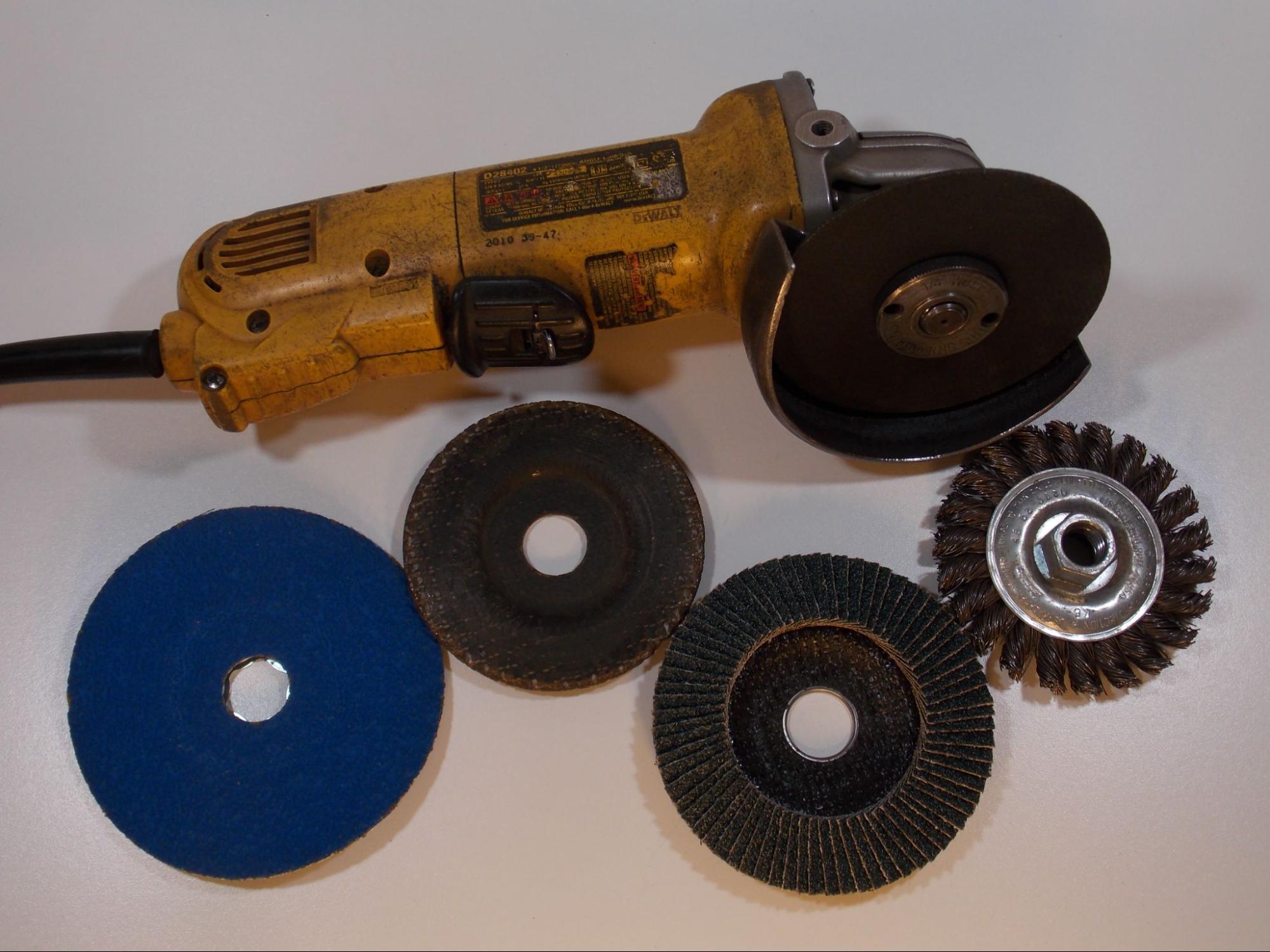
While an angle grinder is mostly thought of as a handy tool for quickly cutting material, it has far more uses. A grinder is quite possibly the most important and versatile power tool any welder can use, and every welder should have a grinder in their tool bag. Grinders can be equipped with numerous abrasive discs and wheels to perform grinding, sanding, cutting, buffing, and other tasks. Grinders are configured for several sizes of discs, such as 4.5 inches, seven inches, and nine inches (11.4 cm, 17.8 cm, and 22.9 cm) diameters. Be sure you have the correct grinder for the size and speed of the disc. Corded and battery-powered models are available.
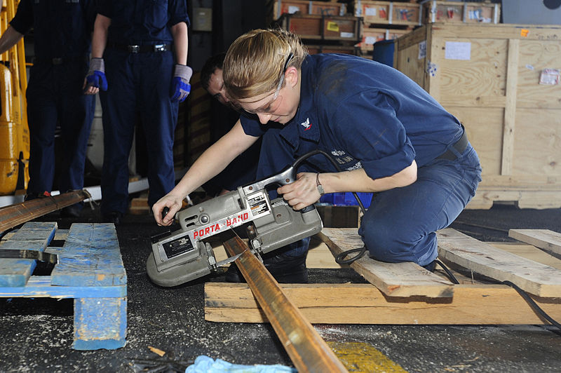
A portable bandsaw, often called a porta band, can be used to easily cut small stock such as bars, tubes, angles, and channels. This tool uses a blade in the shape of a metal band to cut metals and other materials. In fact, with the proper blade, there is almost no material a porta band can’t cut. Most portable bandsaws have a cutting capacity of about five inches (12.7 cm). They are lightweight and easy to take to any job site, and there are corded and cordless models.
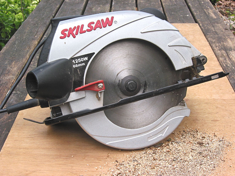
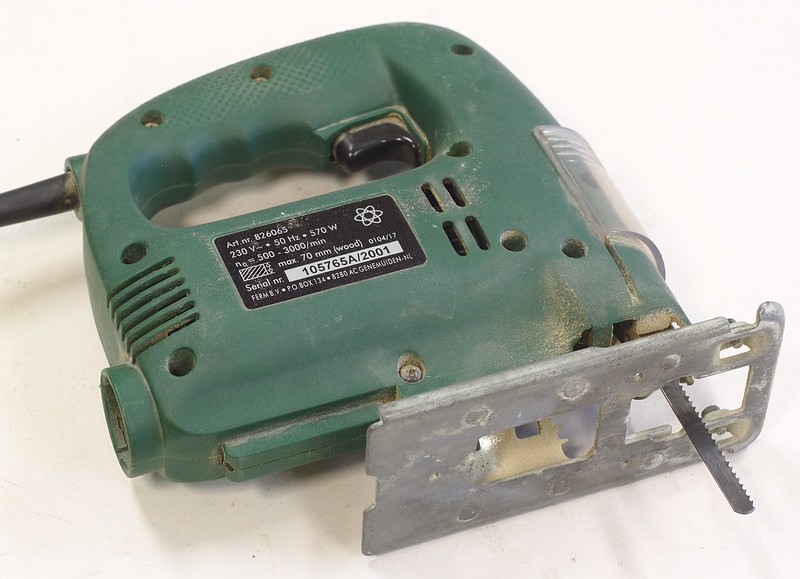
Many welders also use circular saws and jigsaws. These tools effectively cut soft metals such as aluminum and copper. Circular saws are good for cutting material to length and making long, straight cuts while jigsaws can make curved cuts in plate or other stock material. Be aware that you need special blades on either of these tools for these soft metals, as blades meant for cutting wood will dull quickly and may cause damage to the tool, the material, or you. As with other modern power tools, there are both corded and battery-powered models.
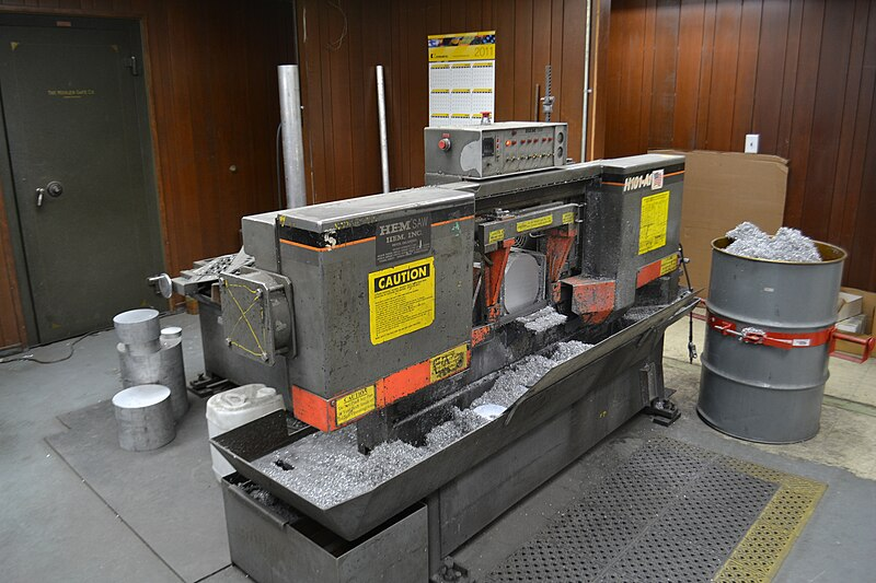
Horizontal bandsaws are staples of any metalworking shop. This high-capacity equipment accurately cuts material to length. When making many of the same parts, these are often the tool of choice to aid in the process, as they are equipped with a stop that the material is butted up to in order to speed up cutting operations. Horizontal bandsaws can cut material with a cross section of over a foot.
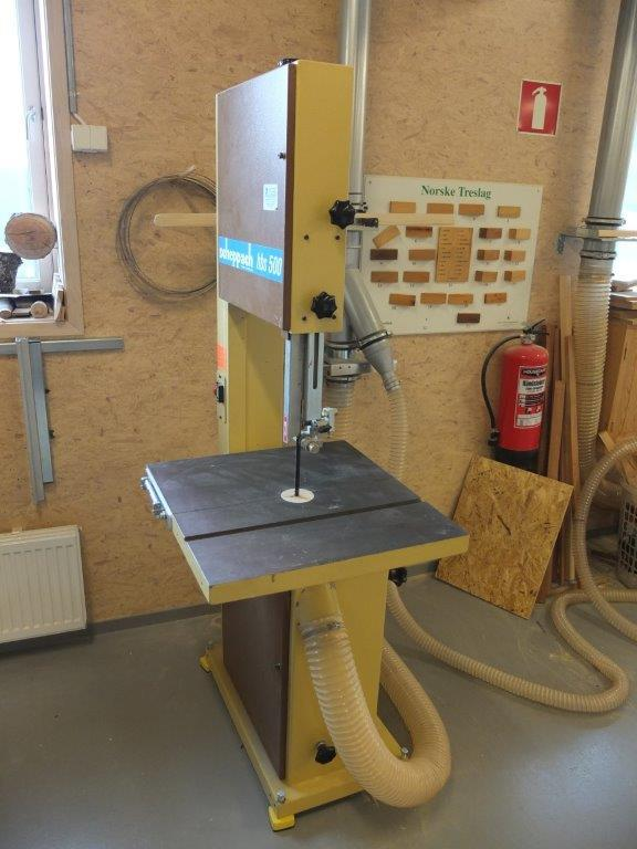
An upright bandsaw is used to make straight, mitered, or curved cuts. Usually the fabricator feeds the material through the saw by hand, giving them more control of the cut. Upright bandsaws are good for making small adjustments to parts that need trimming.
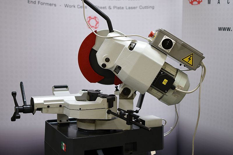
A cutoff saw is another tool for cutting metal stock to length. A cutoff saw can look like a miter saw for wood, but it usually doesn’t have a built-in table and may or may not be able to cut miters. You may also hear this tool called a chop saw or a hot saw. The term hot saw comes from the fact that the blade is actually a thin abrasive disc—much like you would find on a grinder only much larger in diameter—and this kind of blade makes a lot of sparks and heat when cutting. There is another kind of cutoff saw that has a metal blade with teeth that are designed to cut metal. This is often called a cold saw or a dry-cut saw because it produces much fewer sparks and the piece is not heated during cutting. Some cold saws have a lubrication system, as well. As stated above, most cutoff saws don’t come with tables so the fabricator usually must build a table around the saw.
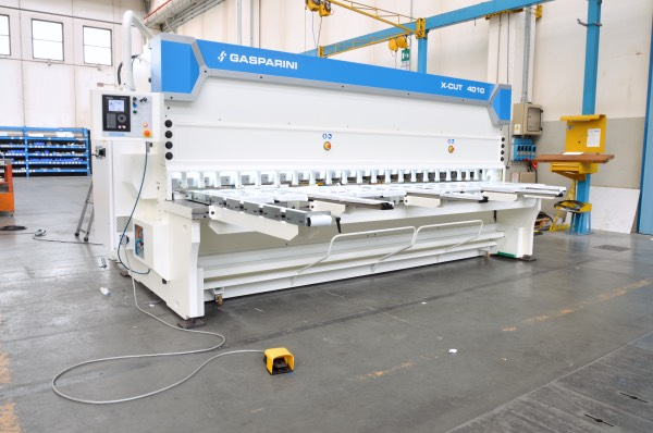
One last piece of cutting equipment to review is the metal cutting shear. Shears are great tools for quickly, cleanly, and accurately cutting metal stock. All of the cutting tools mentioned up until now produce what is called a kerf in the material being cut. Kerf is the amount of material being removed by the blade during cutting. For example, a chop saw’s blade is one-eighth of an inch thick so the kerf taken from a piece of material will be about one-eighth of an inch (3.2 mm) wide. When measuring and cutting parts, the kerf must always be taken into account as part of your measurements—especially when cutting multiples of the same part out of a piece of stock.
A metal shear is the only cutting tool that does not produce a kerf, because it basically acts like a big pair of scissors. The main limitation of metal shears is their cost, size, and the stock shapes that they can cut. Even small shears tend to be expensive, and the larger the shear and the more capabilities it has, the more expensive it will be. Shears have a cutting capacity anywhere from a few inches (or centimeters) to 10 feet (3 m) or more. However, the larger the cutting capacity, the more floor space a shear will take up. Large shears also need at least 220V/240V power. Most shears are designed to cut flat stock such as bars and plates, although some have the ability to cut round stock, angles, and channels through the use of special dies. Finally, some shears are equipped to punch holes or notches in metal.
Drilling Tools
Drilling holes is a common task for many fabricators. There are several tools to accomplish this, including handheld drills, magnetic drills, and drill presses.
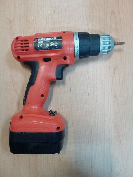
A handheld drill is one of the most common tools in any worker's tool bag. These are great tools for making small holes or driving screws or bolts. Handheld drills can usually take a bit with a shank up to three-eighths or one-half of an inch (9.5 mm or 12.7 mm) in diameter. They can be corded or cordless. Many are meant for light work, but some offer quite powerful speed and torque. There are all manner of drill bits that can be used with this tool.
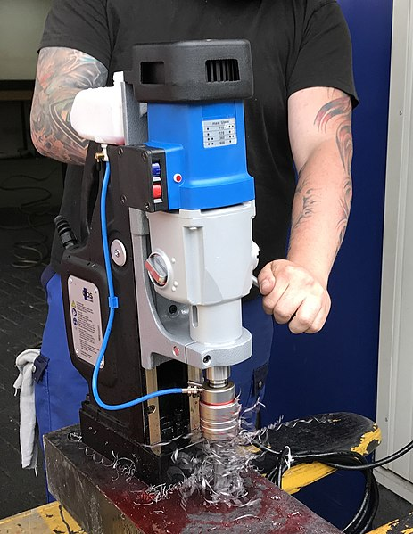
A magnetic drill, or mag drill, is like a portable drill press. They have a powerful magnet on their base that can be turned on and off and allows them to stick to any magnetic surface. By positioning them on material directly over the spot to be drilled, the operation can be carried out with much less effort and more precision than with a handheld drill. Magnetic drills usually have a three-jaw chuck, but they may also have a special chuck that accepts a bit called a rotary broach, or rotabroach. Rotary broaches can be sized anywhere from one-quarter inch (6.35 mm) to over two inches (5 cm), depending on the power of the drill. Most magnetic drills are powered from a wall outlet, but there are a few battery-powered models starting to show up on the market.
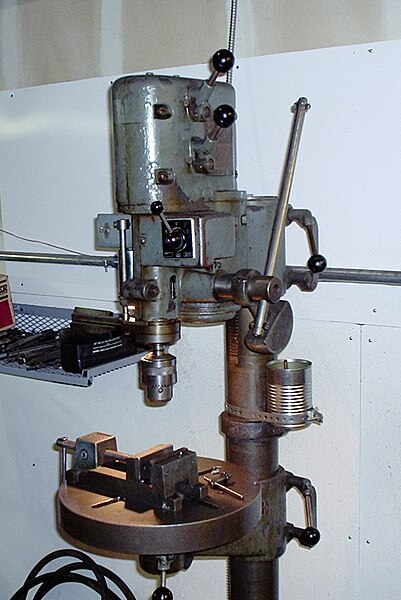
A drill press is a stationary tool for drilling holes. Drill presses have an adjustable table to which the workpiece to be drilled is clamped. This allows a drill press to accommodate a wide range of shapes and sizes of material, as well as drill holes in difficult shapes such as round bars or pipes. They can even drill holes at an angle. Depending on the size and power of the tool, a wide range of drill bits can be used. Drill presses are belt driven and the speed at which the spindle turns can be adjusted by means of the internal belt and pulley system. All of these factors make drill presses very accurate when drilling holes, once you understand how to operate them.
Bending and Forming Tools
Sometimes it is necessary to take a piece of stock material and bend it or roll it to meet the needs of a project. There are several tools to help you accomplish this.
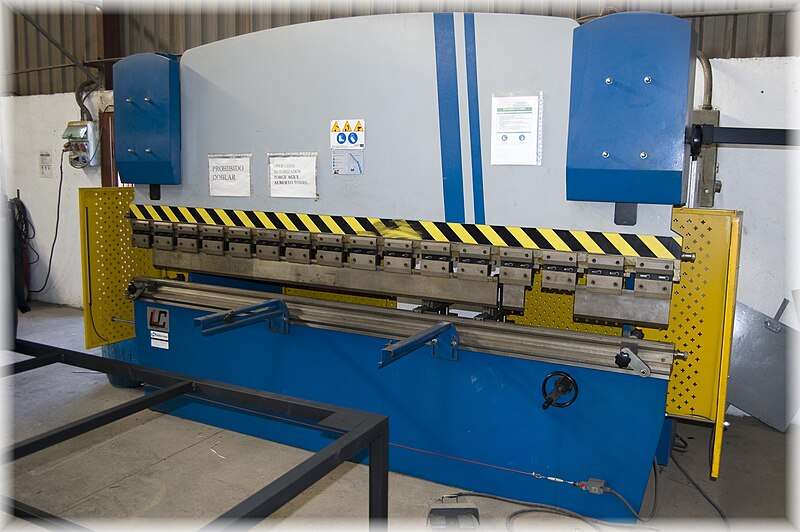
A press brake is a piece of equipment that can precisely put a long, straight bend in a piece of plate. These machines vary widely in size and capability. For instance, a small sheet metal brake is operated by hand and usually can’t bend material thicker than 12 gauge (just under one-eighth of an inch or 3 mm thick). Compare that to a large hydraulic press brake can handle material 10 feet (3 m) wide and one inch (2.5 cm) or more thick, depending on how far it must be bent. The size of a press brake in most shops is determined by the work being done. They are expensive tools and you wouldn’t want to pay for more press brake than you need.
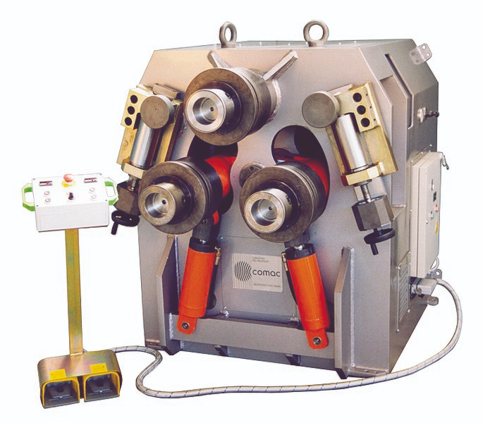
A bending machine curves metal shapes other than flat plates or sheets. There are a number of configurations for this type of machine, but the basic concept is the same: the machine holds two or more sets of dies or rollers, and one set is stationary while the other is affixed to a movable arm. The arm forces the material to be bent around or between the stationary dies or rollers. Many of these machines are meant for small stock and are hand-operated Larger versions make use of hydraulic rams and can bend material up to around two inches (5 cm) in diameter or cross section, depending on the stock shape.
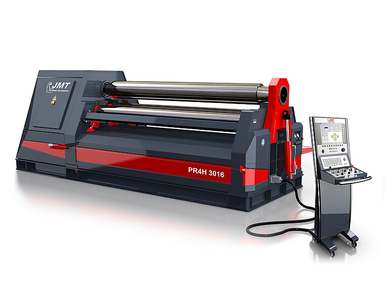
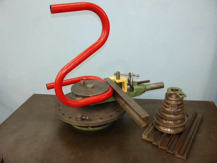
When the desired shape for a workpiece is not a sharp bend but a gentle curve, a metal rolling machine is the tool to use. A slip roller is used to form plates and other flat stock while a ring roller is used to form pipe, tube, angle, and bar stock. Either of these two types of rollers can be hand-driven or electrically powered, depending on their size.
Finish and Surfacing Tools
As their name implies, finish and surfacing tools are used to adjust the surface or edges of parts or welds. They use varying strengths of abrasives to remove material and include angle grinders, die grinders, belt sander, and pedestal grinder.
As stated earlier, angle grinders have a plethora of different abrasive discs that can be used in almost any finishing or surfacing operation.
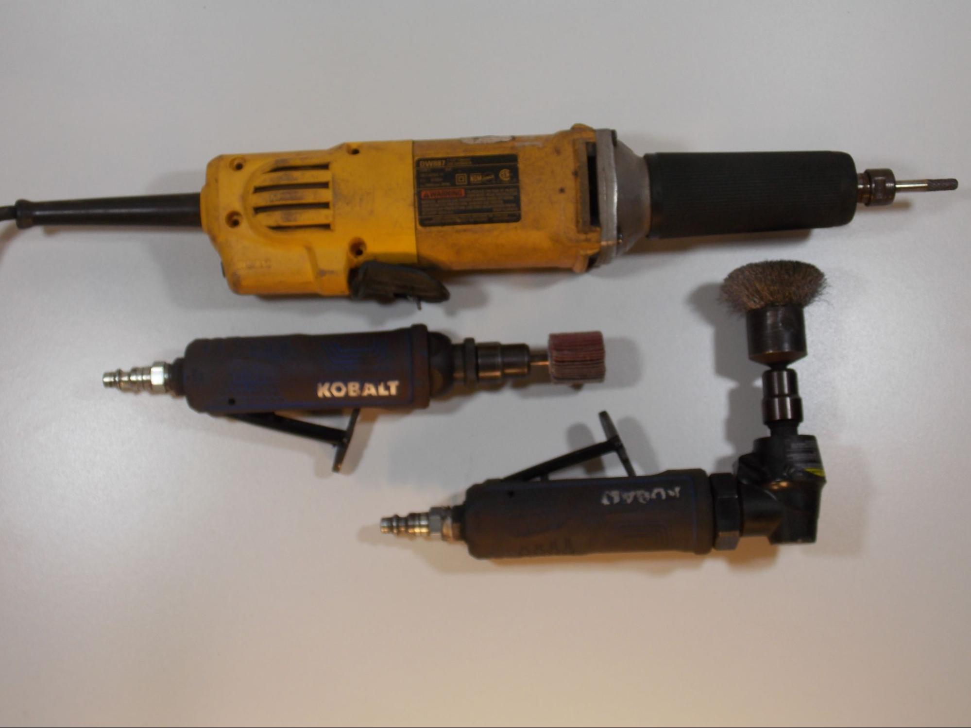
Another type of grinder you may encounter is called a die grinder. Die grinders use a straight spindle and a small bit or bur to reach into corners or holes where it would be hard or impossible to get an angle grinder. The burs are made of carbide and come in different shapes and cutting patterns for hard and soft metals. Sanding and cutting pads can also be attached to a die grinder. They use a straight or 90-degree spindle.
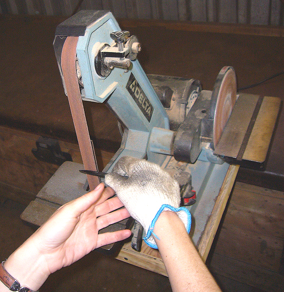
A belt sander is a great piece of equipment to have in any shop. With various sanding grits available, they are useful for deburring parts, shaping material, or polishing the surface of a finished piece. TBelt sanders come in a number of configurations: upright, or horizontal, and with wide or narrow belts. On some models the sanding is done on a flat platen, on others a wheel is used.
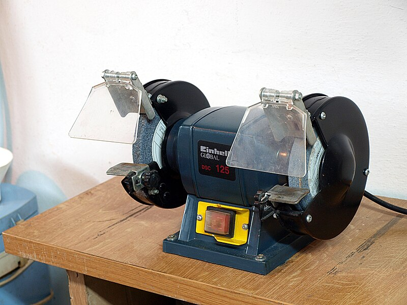
A pedestal grinder works much like a belt sander but rather than a belt has a thick abrasive wheel. Pedestal grinders seem to be losing popularity these days, which may be due to the commonproblem of the wheels becoming misshapen with use, the expense of replacing them, and the increasing popularity of belt sanders. Still, a pedestal grinder is a handy piece of equipment for deburring or shaping material. Also, smaller pedestal grinders can be equipped with a wire wheel for cleaning parts or a buffing wheel for polishing.
Pneumatic Tools
Before moving on, it is worth mentioning that many modern versions of the handheld tools discussed, and even some of the larger pieces of equipment, now have pneumatic versions, meaning they are powered by compressed air. Along with battery-powered tools, pneumatic tools are gaining in popularity. This may be for several reasons. First, pneumatic tools are generally smaller and lighter than their electric counterparts, making them easier to handle. Pneumatic tools with a rotary (spinning) function, such as grinders and drills, have higher revolutions per minute (though less torque), which allows them to accomplish the same work as more powerful electric tools but makes them somewhat safer in the event that something gets caught in the spindle. And, since pneumatic tools are powered by compressed air, a single air compressor attached to a manifold outlet can power many air tools while only taking up one electrical outlet. Finally, pneumatic tools are moderately cheaper than the electric or battery-powered versions of the same kind.
Attributions
- Figure 6.36: Angle Grinder by David Ridge, for WA Open ProfTech, © SBCTC, CC BY 4.0
- Figure 6.37: Defense.gov News Photo 100506-N-6604E-053 - U.S. Navy Petty Officer 3rd Class Ashley Owens uses a portable band saw to cut metal in the hangar bay of the aircraft carrier USS Dwight D by Petty Officer 3rd Class Bradley Evans, U.S. Navy in the Public Domain; This image is a work of a U.S. military or Department of Defense employee, taken or made as part of that person's official duties. As a work of the U.S. federal government, the image is in the public domain in the United States.
- Figure 6.38: Cirkelzaag (Circular saw) by Rasbak is released under CC BY-SA 3.0
- Figure 6.39: Ferm Jig Saw by Dennis van Zuijlekom is released under CC BY-SA 2.0
- Figure 6.40: HE&M Automatic Horizontal Bandsaw by Visitor7 is released under CC BY-SA 3.0
- Figure 6.41: Bandsag by Kai Henning Andersen is released under CC BY-SA 4.0
- Figure 6.42: Cold Saw by Quantum Machinery is released under CC BY-SA 4.0
- Figure 6.43: Gasparini guillotine shear by GaspariniMB is released under CC BY-SA 4.0
- Figure 6.44: Cordless electric (screw) drill by Fructibus is released under CC0
- Figure 6.45: Magnetic Drilling Machine From BDS Maschinen by Rohan von Indien is released under CC BY-SA 4.0
- Figure 6.46: Geared drill press by Bigdumbdinosaur is released under CC BY-SA 3.0
- Figure 6.47: Dobladora by Agranjo is released under CC BY-SA 4.0
- Figure 6.48: DT1Bzeziola by Zeziola is released under CC BY-SA 4.0
- Figure 6.49: Plate Roll by WikiLarousse is released under CC BY-SA 4.0
- Figure 6.50: Bending machine Comac 306 by Валентина Александрова is released under CC BY-SA 3.0
- Figure 6.51: Die Grinder by David Ridge, for WA Open ProfTech, © SBCTC, CC BY 4.0
- Figure 6.52: tool-at-belt-sander-kelen by tickspit is released under CC BY-NC-ND 2.0
- Figure 6.53: Einhell DSC 125 Pa191756 (Nemo5576) by Nemo5576 is released under CC BY-SA 4.0

_drill.jpg)
.jpg)