73 Welding Chrome-Moly Steels
David Colameco, M.Ed.
Basics of welding chrome-moly steels
Molybdenum is used as an alloying element to increase hardenability and improve wear resistance in metal alloys. Molybdenum is also used for creep resistance in fabrications such as pipes that will be under pressure and elevated temperatures for long periods of time in service. Creep is the stretching and deformation of a fabrication’s shape over time at elevated temperatures. For refineries and other chemical processing plants that use high temperatures to process their products, it is very important that the tanks and pipes that are transporting these products maintain their shape over time.
Chrome-moly alloys also come in many shapes that you are familiar with such as plates and pipes. Like stainless steel, chrome-moly alloys require more cleanliness than mild steel does. Proper fit up and cleanliness is important to a good weld of chrome-moly.
This section on chrome-moly is short, but many students find it interesting. If you are interested, take charge of your career and look into career opportunities. Your particular welding program will likely not have chrome-moly material on hand to weld but that doesn’t mean that you can not prepare for welding chrome-moly by getting very good at the welding processes on another material.
Speak with your instructor or career office about local industries that may use chrome-moly and see if there are internships available so you can try it out. It may be possible to get chrome-moly donated to your program but you likely need to show your instructor and program that you are excelling in your welding. Saying that you are interested is different than proving that you are interested. This would make the extra effort of getting chrome-moly material into your program worthwhile. It never hurts to ask your program because the worst thing they can say is no.
Uses of chrome-moly steels in industry today
In general, chrome-moly is used in structural applications such as roll cages for race cars, and in high temperature and pressure applications such as piping for refineries. Chrome-moly is also used in applications such as chain links due to the increased wear resistance that chrome-moly provides, however as a welder you would likely see it in the first two general applications of roll cages and high temperature and pressure piping.
Welding processes used with chrome-moly steels in industry today
GTAW, GMAW, FCAW and SMAW are used for welding chrome-moly alloys in industry, however each specific industry that uses chrome-moly will dictate which process is acceptable.
In the racing industry, GTAW is required by the National Hot Rod Association (NHRA) when welding alloy 4130, while NASCAR on the other hand, uses GMAW-S when welding chrome-moly for its cars (Uttrachi, 2018). For pipe welding, welding consumable manufacturers such as Hobart recommend SMAW and FCAW as the recommended processes (Hobart Brothers, 2023).
Basics of Destructive Examination
Destructive examination involves the destruction of a weldment to determine its mechanical properties and/or visually inspect a cross sectional area of the weld. To imagine what a cross sectional is, think of cutting a pipe in half. The exposed area of the pipe wall where you made your cut is the cross sectional area. Some of us cut better than others; just think of the first time you torch cut something. For destructive examination the cuts are made as precisely as possible using an accurate cutting method and preparation of the surface to ensure that it is smooth for easier identification of discontinuities. See Figure 19.49 and Figure 19.49 for examples of surfaces that have been prepared for examination using macroetching where an acid is used to prepare the cross sectional surface of a weld to see the grains and heat affected zone of a weld.
Uses of Destructive Examination
Destructive examinations allow an inspector or fabricator to see what the inside of a weld looks like. Because destructive tests destroy the weldment, destructive tests are only performed on weldments made for qualification purposes. This qualification can be for a welding procedure, a filler metal, a welder qualification, or other qualification/inspection.
Whenever you perform a code weld, everything from the filler metal, base metal, welding process, welding machine settings, and the welding technique are all qualified and listed on the Welding Procedure Specification (WPS) (See Chapter 18: Welding Procedure Specifications). Filler metals, base metals and welds are destructively tested using bend tests, tensile tests, and Charpy V-notch tests depending upon the code requirements for qualifying a welding procedure which are discussed in the following sections.
Bend Tests
Bend tests do exactly what their name implies. Welds on plates or pipes are cut in accordance with the welding code that is being used. The code will specify the dimensions of the bend test specimens along with the dimensions of the bend testing machine. An example bend testing machine is shown in Figure 19.39 below.
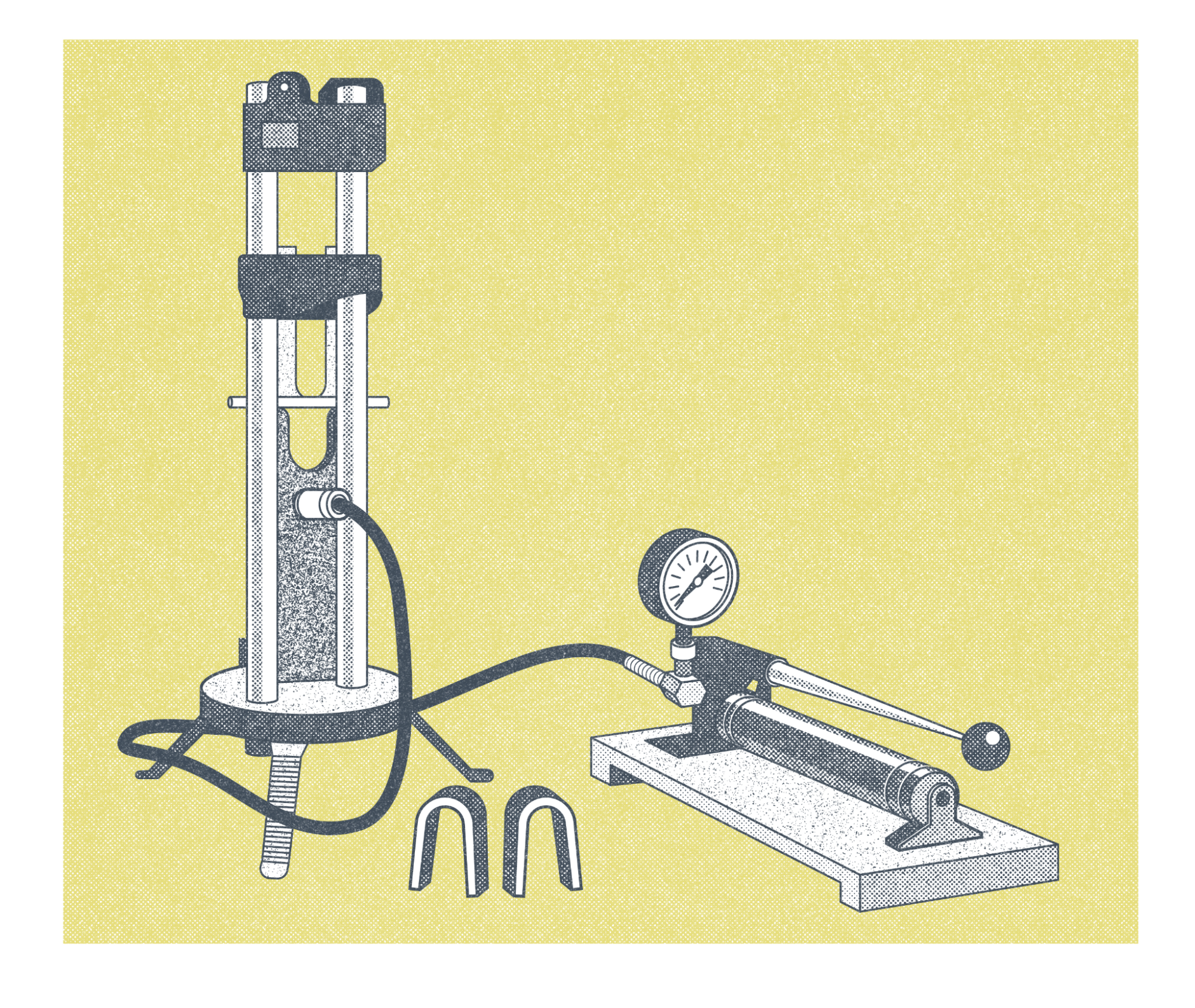
The machine in Figure 19.39 is a mechanical type machine where the operator would have to use the lever to pump air pressure into the machine to apply a force down on the specimen to bend it. If you look closely at Figure 19.39 you can see the straight metal specimen before it is bent sticking out from the sides of the taller portion of the machine with the plunger. Figure 19.39 also shows two bend specimens in the shape of upside down “U”s at the bottom of the Figure in the middle. Actual bend test specimens are shown below in Figure 19.41. Bend tests look at how well the welds are fused to each other and if the metal is solid throughout without any defects. Defects are discontinuities such as tears, slag inclusions, and porosity, that are larger than the acceptable sizes listed in the applicable code.
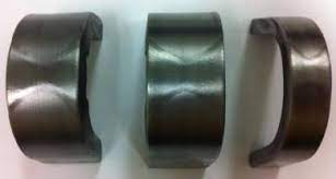
Figure 19.41 shows bend specimens of a double vee groove weld. The two welds can be seen in each of the specimens. The inspector will look for fusion of weld passes to each other and to the base material. Slag inclusions, which are pieces of slag in the weld, will be looked for in weld tests using processes that have slag such as SMAW and FCAW. Tungsten inclusions would be looked for if GTAW or Plasma Arc Welding (PAW) were used. PAW is not discussed in this book, but it is worth mentioning that that process also uses a tungsten electrode. Each code will specify what the acceptable size and/or number of discontinuities can exist in a specimen. Codes also specify any follow on steps if a bend test fails. In some cases additional bend test specimens may be used as specified in the code being used. In other cases the weld test will need to be redone and new samples tested if the bend test fails.
Tensile Tests
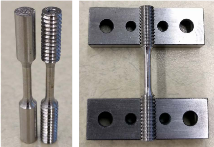
Tensile tests measure the tensile strength of a portion of the weldment. For filler metal test specimens the entire sample is typically only weld metal as specified in the code the filler metal is being tested to. For test specimens that are used to qualify welding procedures or welders, those samples include both base metal and filler metal. Figure 19.42 shows a test plate and the locations where test specimens are cut from the test plate based on AWS D1.5 Bridge Welding. Structural code tests are similar for our discussion.
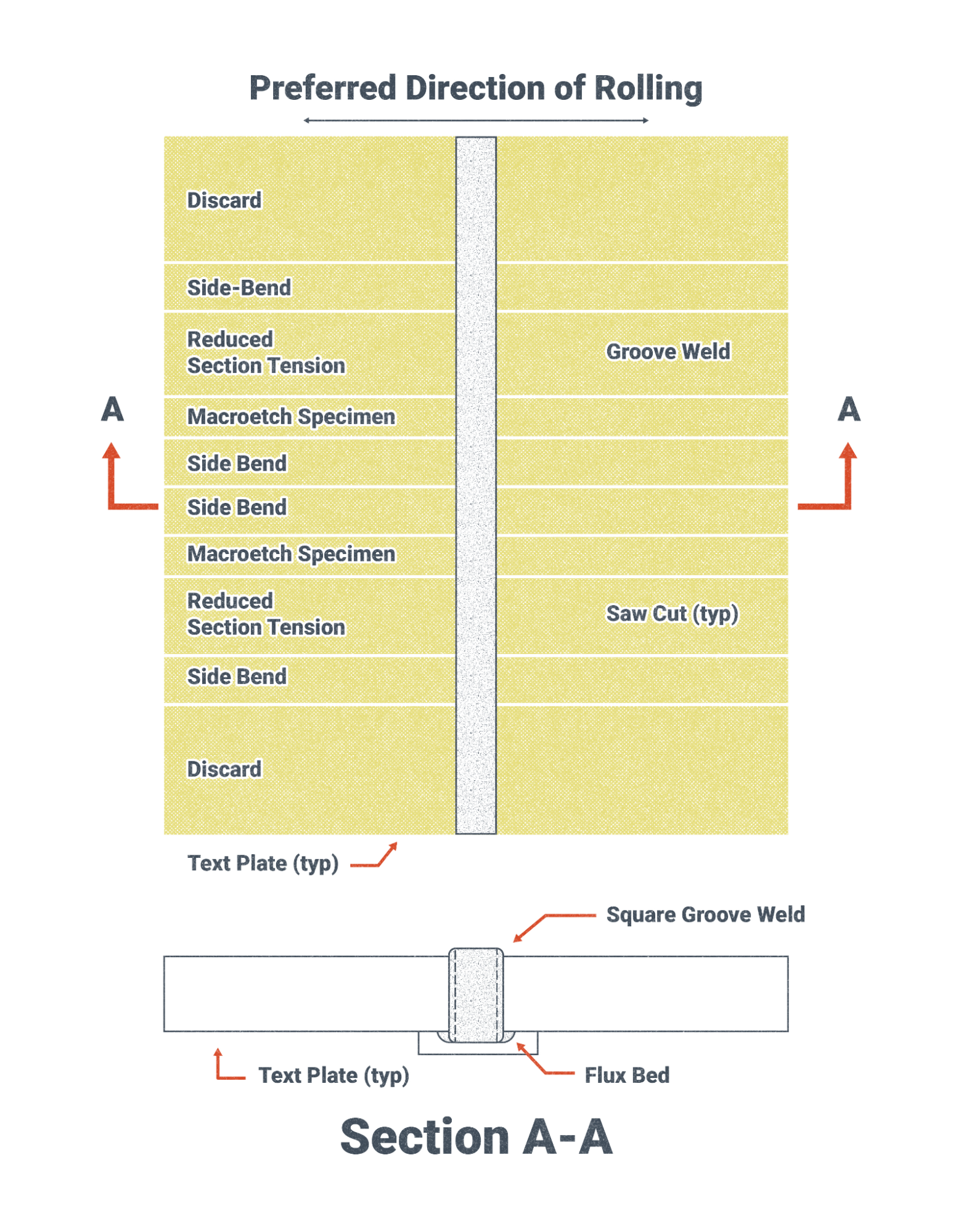
Figure 19.42 shows locations of test specimens that are taken from a test plate. Those specimens are machined to dimensions as specified by the code being used. Figure 19.42 and 19.43 show test specimens that have threads on the ends for placement in a tensile testing machine. The dimensions and tolerances of the specimen ensure consistent tests and tests which are designed to fail in the reduced section.
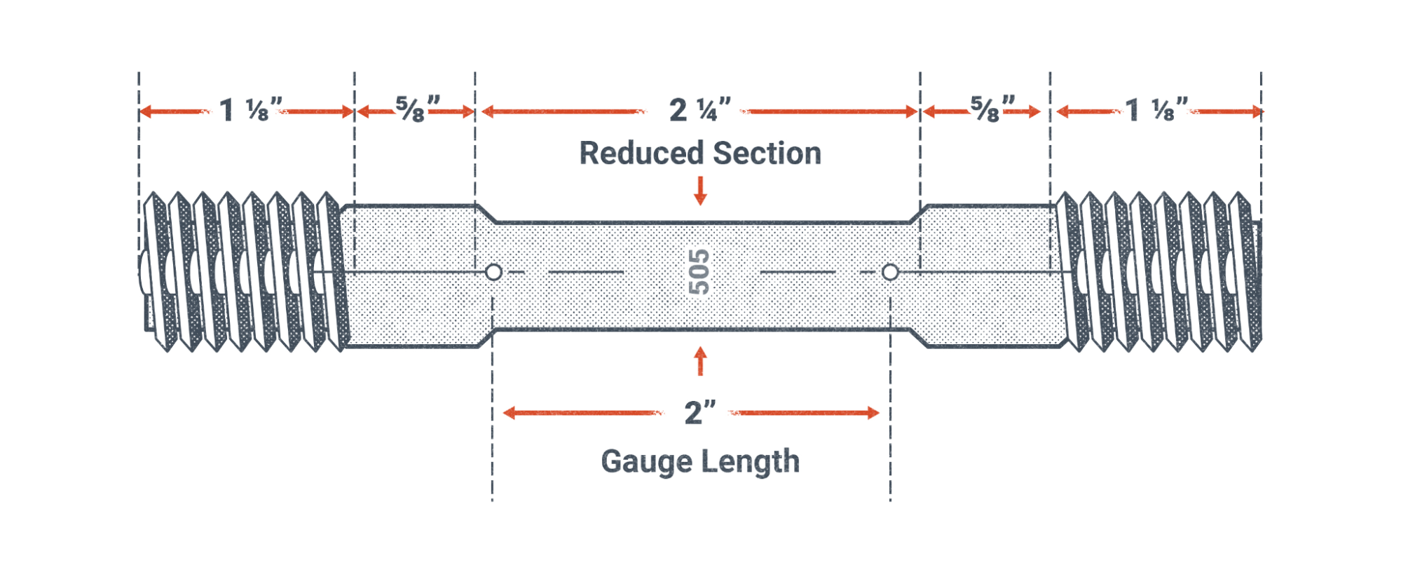
A tensile test machine is shown in Figure 19.44 with the test specimen in the center. The technician on our left looking at the Figure is holding a strain gauge. A strain gauge measures the change in length of the specimen and using the original length before a load was applied can calculate the strain which equals the change in length divided by the original length. The strain gauge is removed from the specimen before the specimen breaks. A computer system is typically used to collect the data from the test setup. The computer program, using the material properties of the specimen’s material, and the data from the test in progress will typically alert the technician to remove the strain gauge. This is done because a strain gauge is an expensive piece of equipment.

The results of the tensile test are compared to the requirements of the code that the test is being performed to. If the test results are within the ranges specified in the code being used, the tests pass.
Charpy V-Notch Tests
Charpy V-Notch tests measure the energy that is absorbed by a test specimen with a “V notch” in it. A hammer is raised to a specific height and is then released to impact the specimen. The mass (commonly referred to as weight) of the hammer and its height when it is swung towards the specimen, determine the energy of the hammer at impact.
The specimen absorbs some energy and the rest of the energy is used by the hammer to travel past the specimen and continue on its arc of travel until it reaches a maximum height. The machine will record the maximum height of the hammer post impact which is used to calculate the energy absorbed by the specimen.
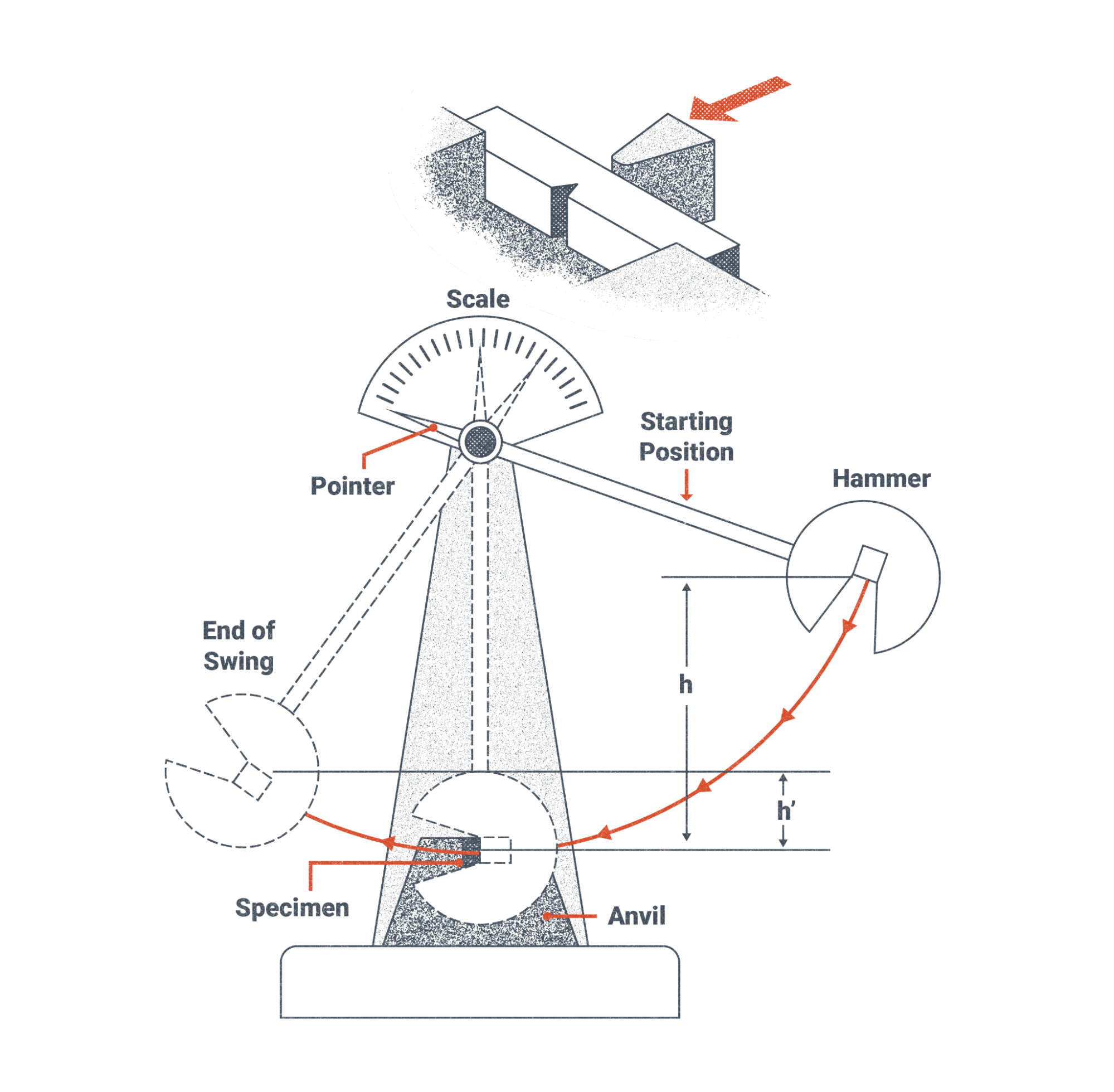
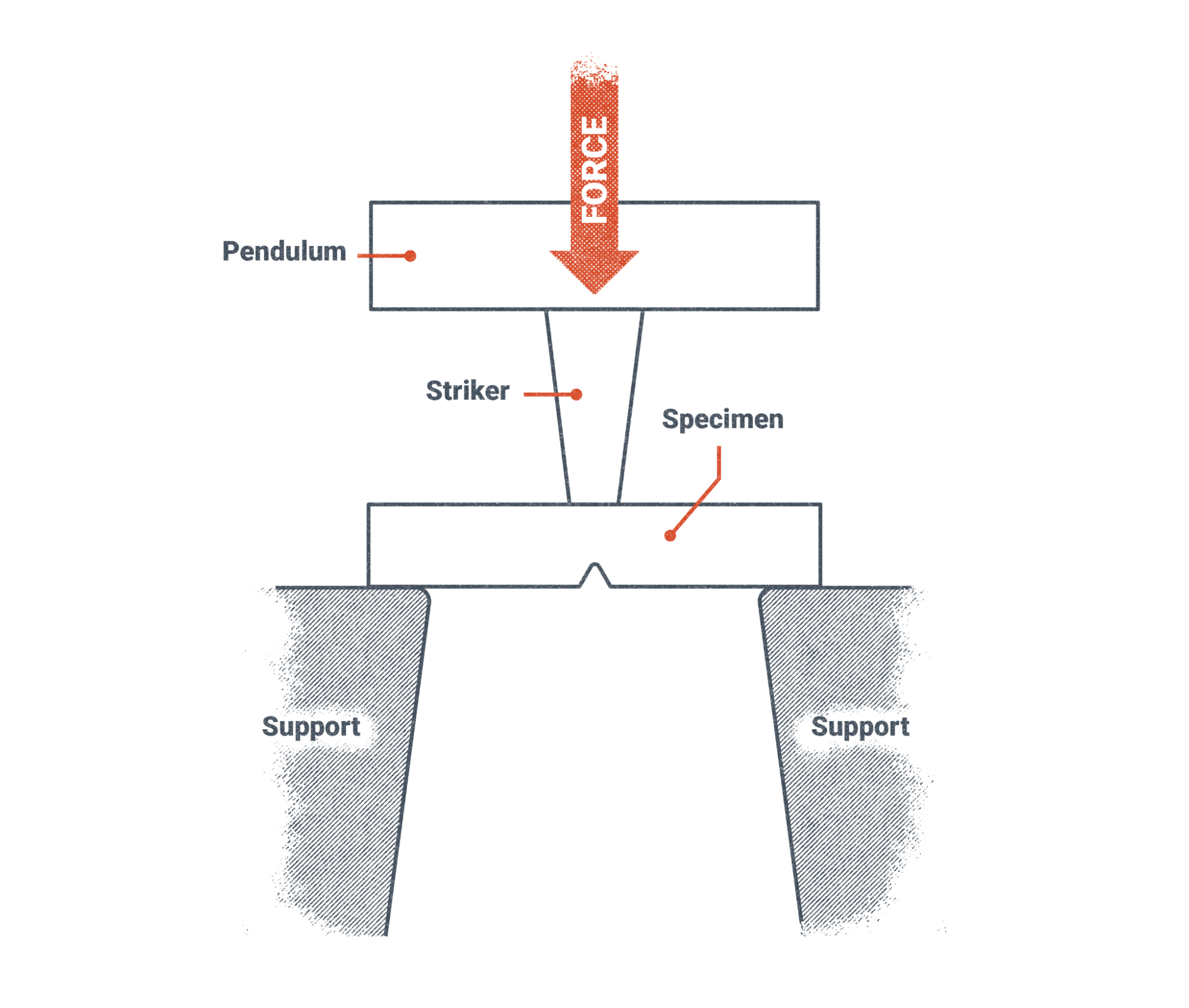
Figure 19.48, below, is an overhead view of the pendulum in Figure 19.45 above. In Figure 19.47 the force of the hammer, or striker as labeled, strikes the specimen opposite of the v-notch. The v-notch provides a weak point where failure of the specimen will occur. Similar to the tensile and bend tests, the Charpy V-Notch tests have requirements in the code being used from the dimensions of the test specimen, specifications for the testing machine, temperatures of the test specimen, and a required range of energy that must be absorbed by the specimen in order for it to pass the test. Materials that can not absorb the specified energy in the standard, are not as strong as they need to be and are at higher risk of failure when the fabrication is subjected to loads.
The successful and thorough fusion of the welds measured in the bend tests, along with the measurement of the tensile strength of the weld using the tensile test, and the tests of the energy that is absorbed by the weld all provide required information about the mechanical properties of the welds that are required for qualification of welding filler metals, welding procedures, and welders and welding operators. The requirements of the tests are specified in the codes being used.
Etching Exposed Surfaces for Visual Inspection
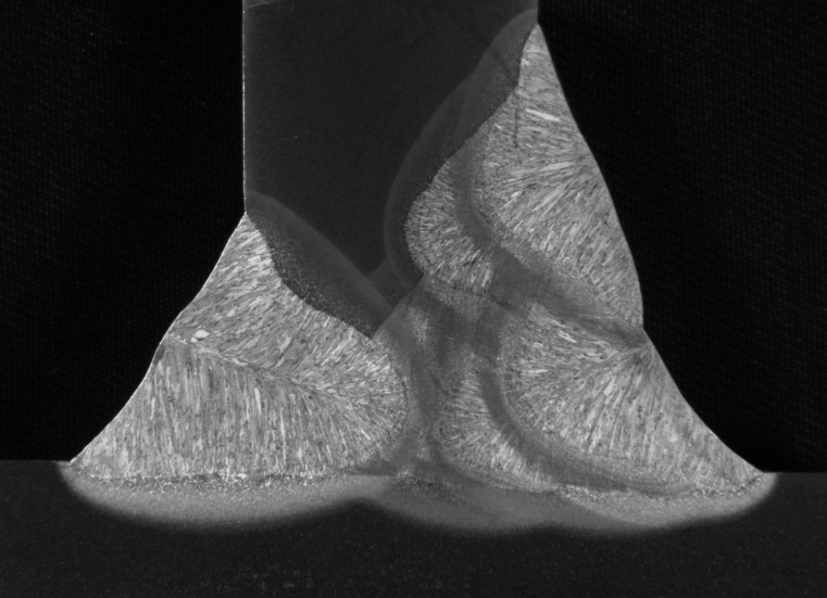
Etching is a destructive test that is used to expose the detail of a cross section of a weld. Figure 19.48 below shows the cross section of a T-Joint. To help visualize the cross section of the weld, imagine welding a T-joint and then cutting the T-Joint in the middle. If you look at the cut surface it resembles a T. That T shape is the cross section of the T-Joint. After the cut is made, the surface is prepared so that it is smooth and an acid is applied to the surface to bring out the detail of the metal grain structure.
In Figure 19.49 you can see the individual weld beads and the heat affected zones of each weld bead. The grain structure can also be seen in the individual weld beads. Figure 19.48 is an excellent high quality example of an acid etch test.
Due to acid etch tests using acids care must be taken when handling acids and acid solutions. Never use acids without permission from your instructor and follow the instructions and precautions on the acid container.
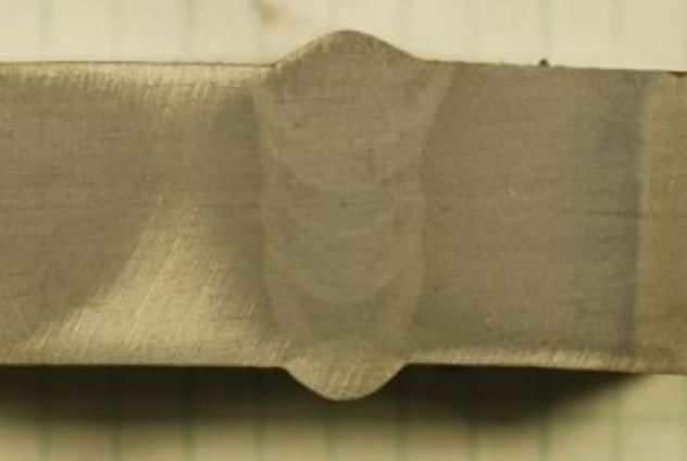
Figure 19.49 is a picture of an acid etch of a butt joint and how it would appear in normal lighting. The individual weld beads are visible, however the grains within the weld are not readily visible.
Attributions
- Figure 19.39: Bend Test Machine by Nicholas Malara, for WA Open ProfTech, © SBCTC, CC BY 4.0
- Figure 19.40: Weldability by U.S. Department of Energy, Advanced Reactor Concepts Program in the Public Domain; United States government work
- Figure 19.41: Test Specimen Locations by Nicholas Malara, for WA Open ProfTech, © SBCTC, CC BY 4.0
- Figure 19.42: Standard Tensile Test Specimen by Nicholas Malara, for WA Open ProfTech, © SBCTC, CC BY 4.0
- Figure 19.43: Left: picture of specimens after machining, Right: a specimen fit to grips by U.S. Department of Commerce, National Institute of Standards and Technology in the Public Domain; United States government work
- Figure 19.44: Aaron Bales, left, and Rob Panaro attach an extensometer to a tensile specimen. The extensometer gives an accurate measure of how much the specimen stretches during a tensile test. by U.S. Department of Energy, National Nuclear Security Administration in the Public Domain; United States government work
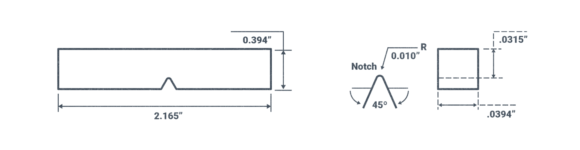
- Figure 19.45: Charpy Test Specimen Dimensions by Nicholas Malara, for WA Open ProfTech, © SBCTC, CC BY 4.0
- Figure 19.46: Charpy V-Notch Test Machine by Nicholas Malara, for WA Open ProfTech, © SBCTC, CC BY 4.0
- Figure 19.47: Charpy Test Diagram by Nicholas Malara, for WA Open ProfTech, © SBCTC, CC BY 4.0
- Figure 19.48: Example macroetch of a T-joint mockup by U.S. Department of Transportation, Federal Highway Administration in the Public Domain; United States government work
- Figure 19.49: Commercial ER100 weld wire by U.S. Department of Energy, Oak Ridge National Laboratory in the Public Domain; United States government work
This section covers the different types of PPE that a welder may encounter on the job pertaining to their eyes. This can be varying types of glasses, a fully enclosed face mask, side shields for glasses, or a welding hood. OSHA 1926.102 is the regulation specific to face and eye protection in construction trades. It also states that if there is an option for either glasses or a face shield, the face shield must provide the same or better protection to the eyes as the required safety glasses for the task. For example, if you’re working as a laser operator, your face shield must be rated for the same UV and IR protection to your eyes as the safety glasses if you don't have to wear both by the employer. While wearing both safety glasses and a welding helmet may not be required, it is highly encouraged.
Glasses
Eye protection should be worn at all times. You only have one set of eyes: choosing the correct glasses can have life-changing effects.
Most employers will set their minimum requirements for their employees. When choosing the appropriate eye protection, consider not only what materials you are working on, but also what is in your surrounding area in your workplace. Are there chemicals, fumes, ash, hot particles, intense light contractions, wood chips, or metal splinters? Do your safety glasses need to withstand impact or flying debris?
General safety glasses that meet the ANSI Z87.1-2020 standard are impact-resistant, clear, and constructed of either plastic (most common) or metal. These are the absolute minimum PPE though, and do not protect against chemicals or splashes.
As a welder, you may be in a shop that does not require that you wear safety glasses under a welding helmet, just that one or the other be worn at all times. Think about the last time you were in a weld shop or school. Consider that when you weld with GMAW, FCAW, or SMAW processes they produce a lot of sparks and molten spatter. You may even see a spark inside your welding hood! More protection is better than less or none at all.
There are safety glasses rated for different work. For example, if you are a welder and a laser cutter your laser-cutting glasses are going to be rated differently and filter out different UV spectrum lights than the standard ANSI A87.1 safety glasses. Several fabrication shops have multiple operations that may require you to change out your PPE depending on where you are in the shop or on a jobsite.
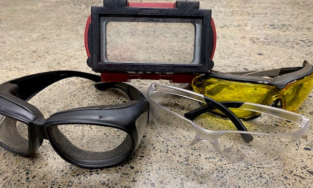
Goggles
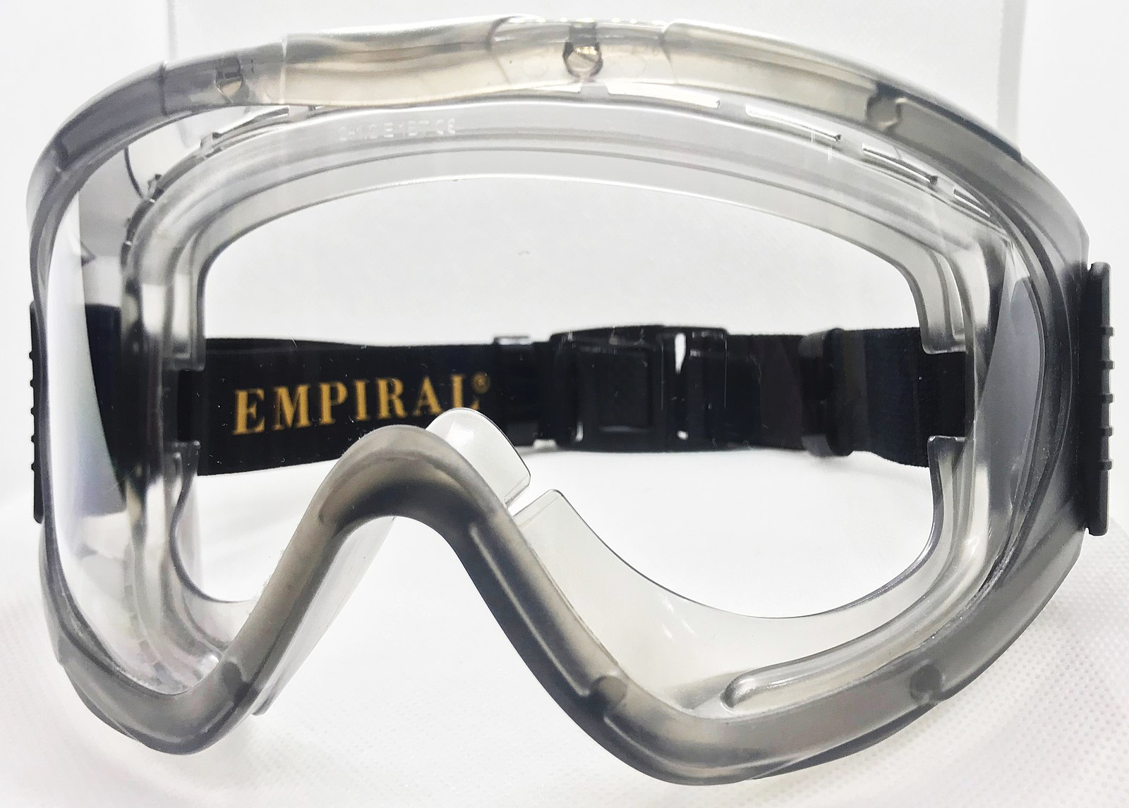
Sometimes there may be a call for something that conceals and secures the eyes even more than safety glasses. Goggles can add that extra layer of protection in areas where there are more airborne particles or chemicals around. There are also welding-specific goggles that offer all-over eye protection by fully covering the eye area while also having removable and changeable lenses.
Tinted welding safety goggles also need to meet ANSI Z87.1 standards and can be worn to protect the eyes during oxy-fuel gas welding and cutting.
Safety goggles also fit over prescription lenses. Impact goggles secure the wearer from flying debris but, due to the vent holes along the sides, they offer no protection from chemicals, dust, and splashes. Chemical splash goggles are required for those working up to 10 feet from the use of a chemical or harmful liquid substance that may produce a splash.
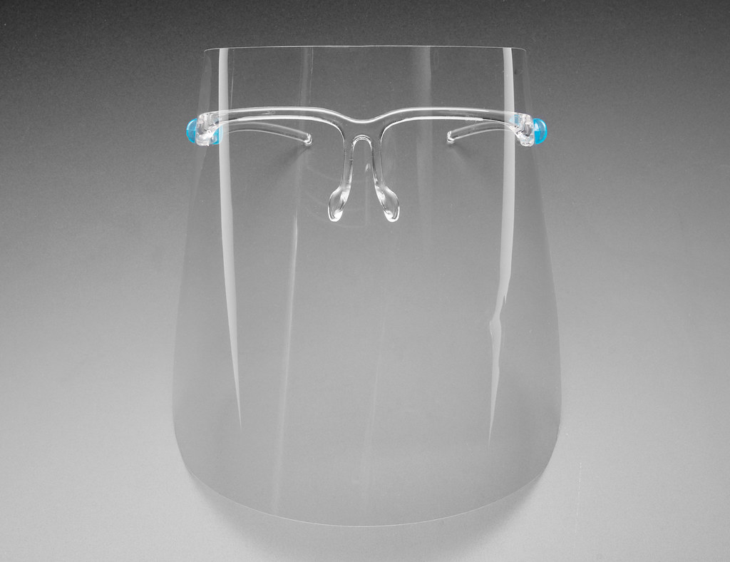
Shields
There are two major different face shields: clear and shaded. Some are even polarized for glare protection. Shaded shields should be worn in congruence with safety glasses during grinding or oxy-fuel gas welding or cutting operations.
OSHA regulations require that “each affected employee uses appropriate eye or face protection when exposed to eye or face hazards from flying particles, molten metal, liquid chemicals, acids or caustic liquids, chemical gases or vapors, or potentially injurious light radiation.” For welders, this may be something as simple as using the grind mode feature on an auto-darkening hood. But in cases where a welder removes their hood to grind, cut, or use chemicals such as nitric acid for etching, they must wear a clear face shield and safety glasses. This applies even if they are inspecting areas where these things are taking place rather than performing the tasks.
Helmets and Hoods
Auto-darkening, fixed-shade, flip-front, and powered air-purifying respirators (PAPR) are all different types of welding helmets and hoods, and the selections are vast. Choosing the right one for you can depend on the demands of a job as well as the cost, fit, style, and your personal preference. In the section below we cover some of the different settings you may encounter on a welding helmet or hood. Not all of these features are available, and not all of them have the same ranges as others.
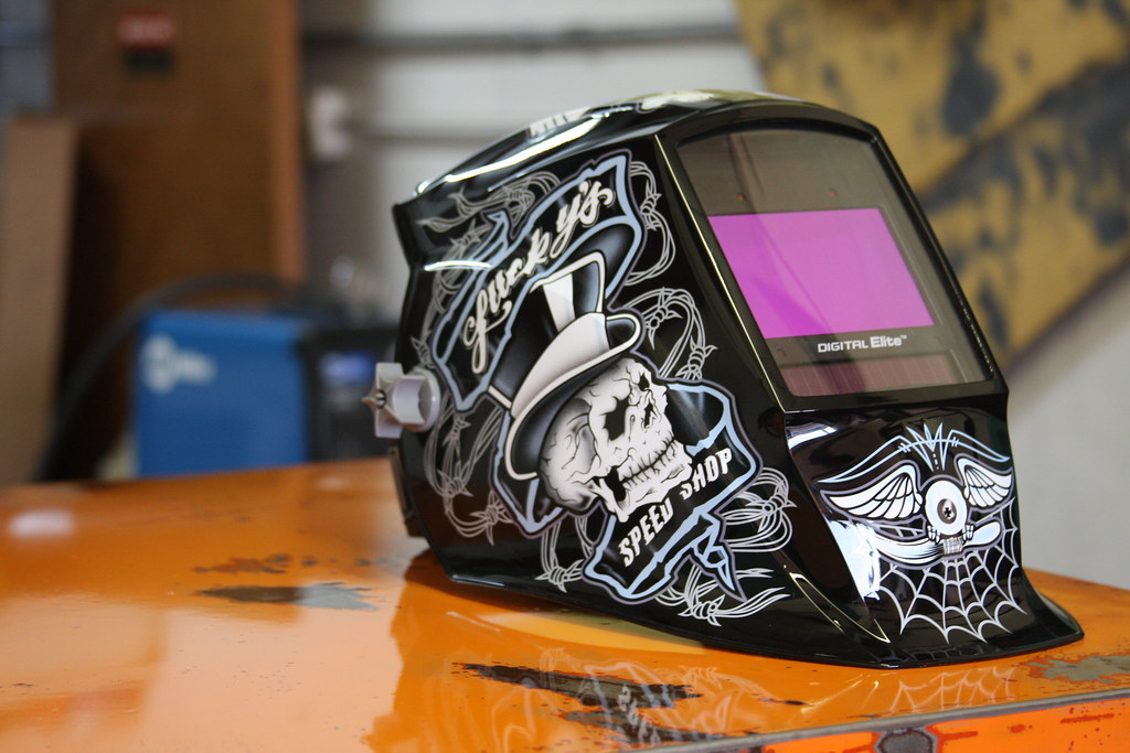
Some welding helmets feature shade adjusters. For auto-darkening welding helmets, the worker can use one helmet for an array of different welding procedures. The helmet will have a sensor that is designed to detect the UV/IR light from the welding arc and then darken the lens to meet the preselected setting.
Fixed-shade helmets do not have this feature. The welder will need to select a darker or lighter lens insert depending on the welding current and operation. Once the welder has pulled their helmet down over their face, they are in the dark until they strike an arc to begin hot work. This means a welder will need to lift their entire helmet and face protection to see after the arc has extinguished.
Flip-front helmets have a clear lens with a flip-down shaded filter plate installed over the viewing window, allowing the welder to lift up the filter plate without removing their helmet to see. This also provides face protection from sparks and debris in the field.
| Process | Electrode Size in. (mm) | Arc Current in Amperes | Minimum Protective Shade No. | Suggested Shade No. (Comfort)* |
|---|---|---|---|---|
| Shielded Metal Arc Welding (SMAW) | Less than 3/32 (2.4)
3/32-5/32 (2.4-4.0) 5/32-¼ (4.0-6.4) More than ¼ (6.4) |
Less than 60
60-160 160-250 250-550 |
7
8 10 11 |
–
10 12 14 |
| Gas Metal Arc Welding (GMAW)
Flux Cored Arc Welding (FCAW) |
Not applicable | Less than 60
60-160 160-250 250-550 |
7
10 10 10 |
–
11 12 14 |
| Gas Tungsten Arc Welding (GTAW) | Not applicable | Less than 50
50-150 150-500 |
8
8 10 |
10
12 14 |
| Air Carbon Arc Cutting (CAC-A) | Light
Heavy |
Less than 500
500-1000 |
10
11 |
12
14 |
| Plasma Arc Cutting (PAC) | Not applicable | Less than 20
20-40 40-60 60-80 80-300 300-400 400-800 |
4
5 6 8 8 9 10 |
4
5 6 8 9 12 14 |
| Plasma Arc Welding (PAW) | Not Applicable | Less than 20
20-100 100-400 400-800 |
6
8 10 11 |
6-8
10 12 14 |
Reference: ANSI Z49.1:2012
*Start with a shade that is too dark to see the weld zone. Then, go to a lighter shade which gives a sufficient view of the weld zone without going below the minimum.
Different welding processes emit different UV/IR rays. UV/IR radiation created by welding arc processes can lead to burns called flash burn: a sunburn-like burn to the skin and eyes that occurs from the light and heat of a welding arc. People passing by hot work, not just those performing the work, are also subjected to flash burns. It's important to refer to the welding equipment manufacturer for the appropriate welding shade setting or proper filter plate before welding or working around welding processes. Never look at a welding arc without the proper PPE.
Filter plates should be marked to identify their shade number and have the letter H stamped into them. The H stamp indicates that the filter plate has been heat treated, is resistant to impact, and won't shatter.
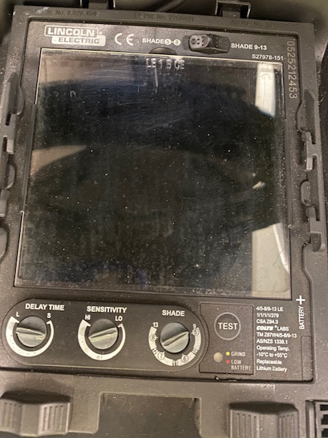
Auto-darkening welding helmets may also have features such as sensitivity and delay time. The sensitivity refers to how much arc light is needed before the helmet will darken. A high-sensitivity setting may cause the helmet to darken when someone is welding within several feet of you. A low-sensitivity setting may not darken in situations where the UV light is low or a welder is watching over another’s shoulder, like a welding instructor over their student’s shoulder. Therefore, these are typically set to the welder’s preference and situation.
Delay time refers to how long it will take until the shade returns to light after an arc has been extinguished. A fast delay will leave little to no time before the lens returns to normal, whereas a long delay may be used if the welder is surrounded by other welders and needs a moment to move out of a nearby arc before the lens returns to normal.
Attributions
- Figure 3.1: image released under the Pexels License
- Figure 3.2: Several types of eye protection by Stephanie Oostman, for WA Open ProfTech, © SBCTC, CC BY 4.0
- Figure 3.3: Empiral Vision Grey goggles by Wishofflying is released under CC BY-SA 4.0
- Figure 3.4: Face Shield with Glasses Frame by Adafruit Industries is released under CC BY-NC-SA 2.0
- Figure 3.5: New Welding Helmet by Weld House LLC is released under CC BY-ND 2.0
- Figure 3.6: A Peek Behind the Hood by Stephanie Oostman, for WA Open ProfTech, © SBCTC, CC BY 4.0
