77 History of Welding Non-Ferrous Metals
David Colameco, M.Ed.
Development of welding non-ferrous metals
Whenever a new fabrication is being developed, the designers will look over existing materials to find ones that meet the mechanical properties required and the desired cost. In some cases the material that is needed for the application does not exist yet. This results in research being conducted to create new metal alloys. These application-specific alloys are why we have so many different alloys. New ferrous alloys are still being invented. However, for specialty applications such as space exploration with its need for high-strength, low-weight, and mechanical properties that can withstand large temperature swings, to high efficiency vehicles which require materials with a high strength-to-weight ratio and other applications with extreme in-service environments, non-ferrous metal alloys have and continue to be developed.
Non-ferrous alloys that are used in mass production in industry today that are weldable are usually welded using the main welding processes that you are learning in your welding labs: Gas Metal Arc Welding (GMAW), and Gas Tungsten Arc Welding (GTAW). GMAW is typically used for higher production fabrication needs if they can produce the quality required for the weldment, such as its use with Aluminum. GTAW is used for its exceptional quality and it can weld many more non-ferrous alloys than GMAW such as the Reactive Metals that will be discussed later in this chapter such as titanium and zirconium.
Low hydrogen electrodes are a must with ferrous metals when welding thick pieces of material or other materials that are subject to hydrogen induced cracking. Likewise, the filler metals’ chemical composition is equally important for welding non-ferrous metals with difficult weldability. For example, filler metal when welding pure aluminum is required because autogenous welds, meaning welds without filler metal, will crack. These filler metals were developed through careful research and trial and error before a workable filler metal alloy was found.
Luckily for us welders, companies are constantly developing better welding machines and better filler metals that make welding easier. For GMAW and GTAW, the welding power supplies are more complex than they used to be. Inverter technology for power supplies enables the welding machine to digitally control the electrical signal that is going to the welders torch or gun. Manufacturers of welding machines develop waveforms that they sell which are specific to the material being welded and the filler material. These waveforms get uploaded to the welding machine, through a usb stick, and the welding machine uses that waveform along with any other welder inputs to the machine such as material thickness, shielding gas etc, and the machine produces an electrical output that enables better welding. This is important for welding non-ferrous metals such as aluminum because it can provide more cleaning action to remove oxidation for those tougher welds. Or you can adjust the amount of penetration vs. cleaning action. This technology can also improve the arc start to make it easier for you to start welding. Chapter 5: Welding Machines covers welding machine power supplies in more detail.
Other welding processes that are beyond the scope of this book are also used to weld non-ferrous metals such as Electron Beam Welding (EBW), Laser Beam Welding (LBW), and Friction Stir Welding to name a few. These welding processes are typically performed by welding operators and not welders because they require precision that is not possible with a manual process and are automated processes. Welders perform manual and semi-automatic welding, while welding operators operate machines that perform automated welding such as welding processes that use robots.
Basics of welding non-ferrous metals
There are always exceptions to the rule, but generally speaking non-ferrous metals have a lower weldability than low carbon steels. Because steel has easy weldability and is less expensive than most alloys, usually that is the go to material. When an application needs to have higher strength, higher corrosion resistance, better ability to survive in-service conditions, or a higher strength to weight ratio, other metal alloys are used.
Non-ferrous materials like aluminum do not give off red light when heated to an elevated temperature like ferrous metals. This means that you can’t tell if a metal like aluminum is hot just by looking at it. This means that you need to know how the non-ferrous alloy will react to heating and if it will glow or not. The material’s rate of expansion when heated becomes important because the alloy may shrink more than initially expected leading to higher stresses in the weldment and possibly cracking.
In addition, metals like aluminum oxidize very quickly. The rust on iron is oxidation; oxidation can flake off or remain on the metal. We prefer metals that form an oxide layer that remains to protect the underlying base material. The oxide layer on aluminum starts to form immediately after cleaning; if you take a break after cleaning your aluminum you should clean it again to remove any new oxide layer that formed.
Stainless steel wire brushes are typically used for cleaning and working with aluminum and titanium alloys. It is important to mark the handle of these tools with “Aluminum Only” or “Titanium Only” so you do not contaminate your metal by using the brush on another material.
Reactive metals react very strongly with oxygen and nitrogen, both of which are found in air, making the application of adequate shielding gas a must. Sometimes these metals are welded in a glove box so the entire environment of the weldment consists of the shielding gas. The welding glove box is a box with gloves attached that provides a barrier to the outside atmosphere but allows you to place your hands in the gloves to manipulate items in the box.
These non-ferrous alloys typically have specific alloying elements that give the metals their unique properties. This makes the selection of filler metals very important. The WPS for welding non-ferrous metals needs to be followed even more carefully because non-ferrous alloys, especially reactive metals, are much less forgiving to mistakes and/or contamination.
Uses of non-ferrous metals in industry today
Non-ferrous metals such as Aluminum are used for electrical and structural applications due to its high strength to weight ratio. Reactive metals, such as titanium, zirconium, and beryllium are used in harsh environments with corrosive or radioactive substances.
Titanium has an excellent strength to weight ratio, making it an alloy used in the aerospace industry, and it has high corrosion resistance making it a good choice for desalination parts to obtain clean drinking water from sea water. Due to titanium’s corrosion resistance, or lack of reaction to water, titanium is used in medical and dental implants.
Zirconium is used by the nuclear industry in nuclear power plants, especially for the tubes that hold the ceramic fuel pellets because it performs well in high temperature high radiation environments. Zirconium, like titanium, is also highly corrosion resistant and is used in medical and dental implants.
Beryllium is a high strength, highly corrosive resistant metal that is used in the nuclear, aviation, and space industries. This is a highly poisonous metal that should only be fabricated by trained personnel. Undisturbed, the metal is ok to handle. It’s the dust from machining that causes berylliosis of the lungs which is a life threatening disease. Your body will have an immune response to inhaled beryllium that could be immediate or take months or years to develop. Anytime you work with a new metal or material it is important that you understand what you are working with so you can safely produce fabrications and not cause unnecessary damage to your health.
This is where you can add appendices or other back matter.
Welding is a skill that holds immense potential for creating and shaping, yet it is not without its share of risks and hazards. To embark on a welding journey with confidence and competence, it is crucial to navigate and mitigate common welding hazards effectively. By understanding these hazards and implementing appropriate safety measures, welders can ensure their well-being while achieving exceptional results. This reading presents a comprehensive guide to navigating common welding hazards and prioritizing safety in the welding environment.
Arc Flash and Electrical Shock
Arc flash and electrical shock are inherent dangers in welding, particularly during processes like Shielded Metal Arc Welding (SMAW) and Gas Metal Arc Welding (GMAW). The intense light emitted during welding can cause arc flash, potentially leading to eye injuries. Furthermore, improper handling of electrical equipment can result in electrical shock. To navigate these hazards:
- Utilize proper welding helmets with auto-darkening filters to shield your eyes from arc flash.
- Wear dry and insulating gloves and protective clothing to minimize the risk of electrical shock.
- Inspect cables, connectors, and electrical equipment for damage before use, and avoid water or damp areas while welding.
Fire and Explosions
Welding generates extreme heat, sparks, and molten metal, all of which pose a fire hazard. Additionally, when working with flammable materials or in confined spaces, the risk of explosions increases. To mitigate these hazards:
- Clear the work area of flammable materials, liquids, and gases before starting the welding process.
- Place fire-resistant blankets or screens around the welding area to prevent sparks from igniting nearby objects.
- Have a fire extinguisher readily available and ensure all workers know how to use it effectively.
Toxic Fumes and Gases
Welding produces fumes and gases that, if inhaled, can lead to respiratory issues and long-term health problems. Welders must be vigilant about controlling exposure to these hazardous substances. To address this concern:
- Work in well-ventilated areas, ideally with local exhaust ventilation to remove fumes and gases at the source.
- Wear proper respiratory protection, such as N95 respirators or powered air-purifying respirators, when working in confined spaces or areas with inadequate ventilation.
Burns and UV Radiation
The intense heat generated during welding can lead to severe burns on the skin and eyes. UV radiation emitted during welding can cause arc eye, a painful condition similar to sunburn. To protect against burns and UV radiation:
- Wear flame-resistant clothing, including long sleeves, pants, and leather aprons, to shield the skin.
- Employ appropriate welding helmets with shaded lenses to prevent arc eye and protect your eyes from harmful UV rays.
Noise and Hearing Damage
Welding processes produce noise levels that can lead to hearing damage over time. To safeguard your hearing:
- Wear hearing protection, such as earplugs or earmuffs, especially when engaged in prolonged welding tasks or working in noisy environments.
Navigating these common welding hazards necessitates not only awareness but also proactive measures. By following safety protocols, using appropriate personal protective equipment (PPE), and adhering to industry guidelines, welders can confidently tackle their projects while minimizing risks.
1F: Flat Fillet Test Position
1G: Flat Groove Test Position
2F: Horizontal Fillet Test Position
2G: Horizontal Groove Test Position
3F: Vertical Fillet Test Position
3G: Vertical Groove Test Position
4F: Overhead Fillet Test Position
4G: Overhead Groove Test Position
5F: Multiple Position Fillet Test Position (Pipe axis is horizontal and pipe not rotated)
5G: Horizontal Position Groove Test Fixed Position
6G: Inclined Groove Test Position
6GR: Inclined Groove Test Position with a Restriction Ring
A: Amps
AAC: Air Arc Cutting
ABANA: Artists-Blacksmiths Association of North America
ABS: American Bureau of Shipping
AC: Alternating Current
AD: Anno Domini, medieval latin for in the year of our Lord
AISC: American Institute of Steel Construction
ALARA: As Low As Reasonably Achievable
AM: Additive Manufacturing
ANSI: American National Standards Institute
AOC: United States Architect of the Capitol
API: American Petroleum Institute
ASME: American Society of Mechanical Engineers
ASNT: American Society of Nondestructive Testing
ASTM: American Society of Testing and Materials
AWS: American Welding Society
BHN: Brinell Hardness Number
BLM: Bureau of Land Management
BPVC: ASME Boiler and Pressure Vessel Code
°C: Degree Centigrade
CAC: Carbon Arc Cutting
CAC-A: Carbon Arc Cutting - Air
CAW: Carbon Arc Welding
CBO: United States Congressional Budget Office
CC: Constant Current
cm: centimeter
CV: Constant Voltage
CFH: Cubic Feet Per Hour
CFM: Cubic Feet per Minute
CFR: US Code of Federal Regulations
CJP: Complete Joint Penetration
CL: Center Line
CLAMS: Current, Arc Length, Angle, Manipulation, and Travel Speed
CNC: Computerized Numerical Control
CP: Constant Potential
CPSC: United States Consumer Product Safety Commission
CTWD: Contact Tip to Work Distance
CWI: Certified Welding Inspector
dB: decibel
DC: Direct Current
DCEN: Direct Current Electrode Negative
DCEP: Direct Current Electrode Positive
DCSP: Direct Current Straight Polarity
DCRP: Direct Current Reverse Polarity
DE: Destructive Examination
DLA: United States Defense Logistics Administration
DOC: United State Department of Commerce
DoD: United States Department of Defense
DOE: United States Department of Energy
DOI: United States Department of the Interior
DOL: United States Department of Labor
DOSH: Division of Occupational Safety and Health
DOT: United State Department of Transportation
DT: Destructive Testing
EBW: Electron Beam Welding
ECT: Eddy Current Testing
°F: Degree Fahrenheit
FCAW: Flux Cored Arc Welding
FCAW-G: Flux Cored Arc Welding - Gas Shielded
FCAW-S: Flux Cored Arc Welding - Self Shielded
FHWA: Federal Highway Administration
FMA: Fabricators & Manufacturers Association of America
FRP: Fiber Reinforced Plastics
FSW: Friction Stir Welding
ft: feet
FW: Flash Welding
GAWDA: Gas and Welding Distributors Association
GMAW: Gas Metal Arc Welding
GMAW-P: Gas Metal Arc Welding - Pulse Spray Transfer
GMAW-S: Gas Metal Arc Welding - Short Circuit
GTAW: Gas Tungsten Arc Welding
HAZ: Heat Affected Zone
HIC: Hydrogen Induced Cracking
Hz: Hertz
IFI: Industrial Fasteners Institute
IIW: International Institute of Welding
INL: Idaho National Laboratory
IPM: Inches Per Minute
IR: Infrared
IQI: Image Quality Indicator
kg: kilogram
ksi: thousand pounds per square inch
L&I: Labor and Industries
LANL: Los Alamos National Laboratory
lbs: pounds
LBW: Laser Beam Welding
LOF: Lack of Fusion
LT: Leak Testing
m: meter
MAG: Metal Active Gas
MIG: Metal Inert Gas
mm: millimeter
MT: Magnetic Particle Testing
NASA: National Aeronautics and Space Administration
NAVEDTRA: Naval Education and Training Center
NAVSEA: Naval Sea Systems Command
NDE: nondestructive Examination
NDT: nondestructive Testing
NIOSH: National Institute for Occupational Safety and Health
NRR: Noise Reduction Rating
OAC: Oxy-acetylene Cutting
OAW: Oxyacetylene Welding
OFC: Oxy Fuel Cutting
ORNL: Oak Ridge National Laboratory
OSHA: United States Occupational Safety and Hazards Administration
PAC: Plasma Arc Cutting
PAPR: Positive Air Purifying Respirator
PAUT: Phased Array Ultrasonic Testing
PAW: Plasma Arc Welding
PJP: Partial Joint Penetration
PPE: personal protective equipment
psi: pounds per square inch
psig: pounds per square inch gauge
PT: Die Penetrant Testing
PW: Projection Welding
PWHT: Post Weld Heat Treatment
pWPS: preliminary Welding Procedure Specification
REA: United States Rural Electrification Administration
RPM: Revolutions per Minute
RSEW: Resistance Seam Welding
RT: Radiographic Testing
RW: REsistance Welding
SAR: Supplied Air Respirator
SAW: Submerged Arc Welding
SDS: Safety Data Sheet
SMAW: Shielded Metal Arc Welding
SS: Stainless Steel
TIG: Tungsten Inert Gas
TSP: Tri Sodium Phosphate
TWA: Time Weighted Average
TYP: Typical
UN: Unless Noted
UNO: Unless Noted Otherwise
USGS: United States Geological Survey
UT: Ultrasonic Testing
UV: Ultraviolet
V: Volts
VT: Visual Testing or Examination
W: Watts
WA: Washington State
WABO: Washington Association of Building Officials
WFS: Wire Feed Speed
WISHA: Washington Industrial Safety and Health Act
WPS: Welding Procedure Specification
WSDOT: Washington State Department of Transportation
I
Components
The equipment needed for GTAW include a welding power source, shielding gas, regulator and flow meter, electrode holder (known as a torch), tungsten electrode, filler rods, foot pedal or handheld power control, water cooler (when required), and personal protective equipment (PPE).
Welding Power Source
Most welding machines are capable of GTAW; the machine must be a constant current power source.
Some features on a power source built for GTAW include:
- Capabilities to run on direct current electrode positive (DCEP) or direct current electrode negative (DCEN).
- Alternating current (AC) functionality, which is often used to weld aluminum and magnesium. Some machines will give the operator the ability to adjust the balance of the AC wave and even control the shape of the wave.
- A solenoid valve that controls shielding gas flow and cooling water (if water cooler is attached).
- A foot pedal or handheld remote control that gives the operator the ability to not only turn on and off the flow of gas and current but also to increase or decrease the current while welding. Some machines will have a pre-flow to make sure the arc is protected from the beginning. Post-flow is used once you terminate the weld: the shielding gas continues to flow for a set duration of time to protect the weld as it cools. You will not want to move the torch at all during this time or lift your hood.
- The ability to run at a high frequency, allowing the operator to start an arc without touching the base metal.
Direct Current
There are two modes for direct current: DCEP, which is also known as reverse polarity, and DCEN, which is known as straight polarity. When the machine is set to straight polarity, the electrons flow from the electrode to the work in a way that directs the heat on your workpiece and not your electrode in a 70/30 split. This means 70% of the heat being created is on the work, and 30% is on the electrode. This is the most common way to set up a GTAW machine because it minimizes the wear and tear on electrodes.
When the welding machine is set up for reverse polarity, the electrons flow from the work to the electrode in a way that puts 70% of the heat on your electrode and 30% of the heat on the workpiece. When you have a non-consumable electrode—as you do with GTAW—this can be a detrimental process. However, there are benefits to using this polarity, because as the electrons flow up from the workpiece, positively charged ions strike the metal, breaking up the oxides on the surface of your work, which is a wonderful cleaning action. Also, setting the machine up this way will give you a very wide, shallow puddle. A fun thing to practice once or twice is to get a very thin sheet of aluminum and try to weld it with reverse polarity. Using a thicker tungsten is recommended, and even then you will notice it takes a lot of wear and tear.
Alternating Current
Alternating current continuously switches from DCEP to DCEN at 60 Hz, making this switch 60 times per second. The purpose of using AC while employing GTAW is to take advantage of the benefits of straight and reverse polarities at the same time. The advantages are extremely useful when welding aluminum, as you can break up the oxide on the surface and direct enough heat to the workpiece to weld.
There are three main factors to consider when using AC for welding: balance, frequency, and waveform. Not all machines will have the ability to manipulate all of these factors, though.
Balance gives you the ability to favor DCEP or DCEN. If your machine is set to 75/25 in favor of DCEN, the arc will be on DCEN for 75% of the time. Imagine 0.1 of a second of welding drawn with a 50/50 AC wave—positive on top, negative on the bottom, and 0 in the middle. This would result in six equal humps on both sides. The wave will stay on the negative side of the 0 three times as long as on the positive side. This would give you more penetration and less cleaning. But set the machine to 25/75 favoring DCEP and the wave would stay on the positive side of 0 for longer. This would give the arc more cleaning action and less penetration. It would also put much more heat on your tungsten.
The frequency setting on a welding power source affects how often the arc switches from DCEP to DCEN per second. Not all machines have this feature, and if they do the ability for machines to adjust the frequency will vary from as low as 20 Hz to as high as 350 Hz. At lower frequencies the arc cone is wider, and at higher frequencies the arc cone will be tighter, which can help to get into tight corners. If you are working with a machine with the ability to adjust frequency settings, it is highly recommended that you experiment with both extremes. However, a great generic setting for everyday welding is 110 Hz.
Note that high frequency is a separate function from your frequency adjustment. This function is intended to jump the gap between your tungsten and work to initiate your arc without contaminating your tungsten. It is also meant to maintain a stable arc during AC welding.
AC Waveforms
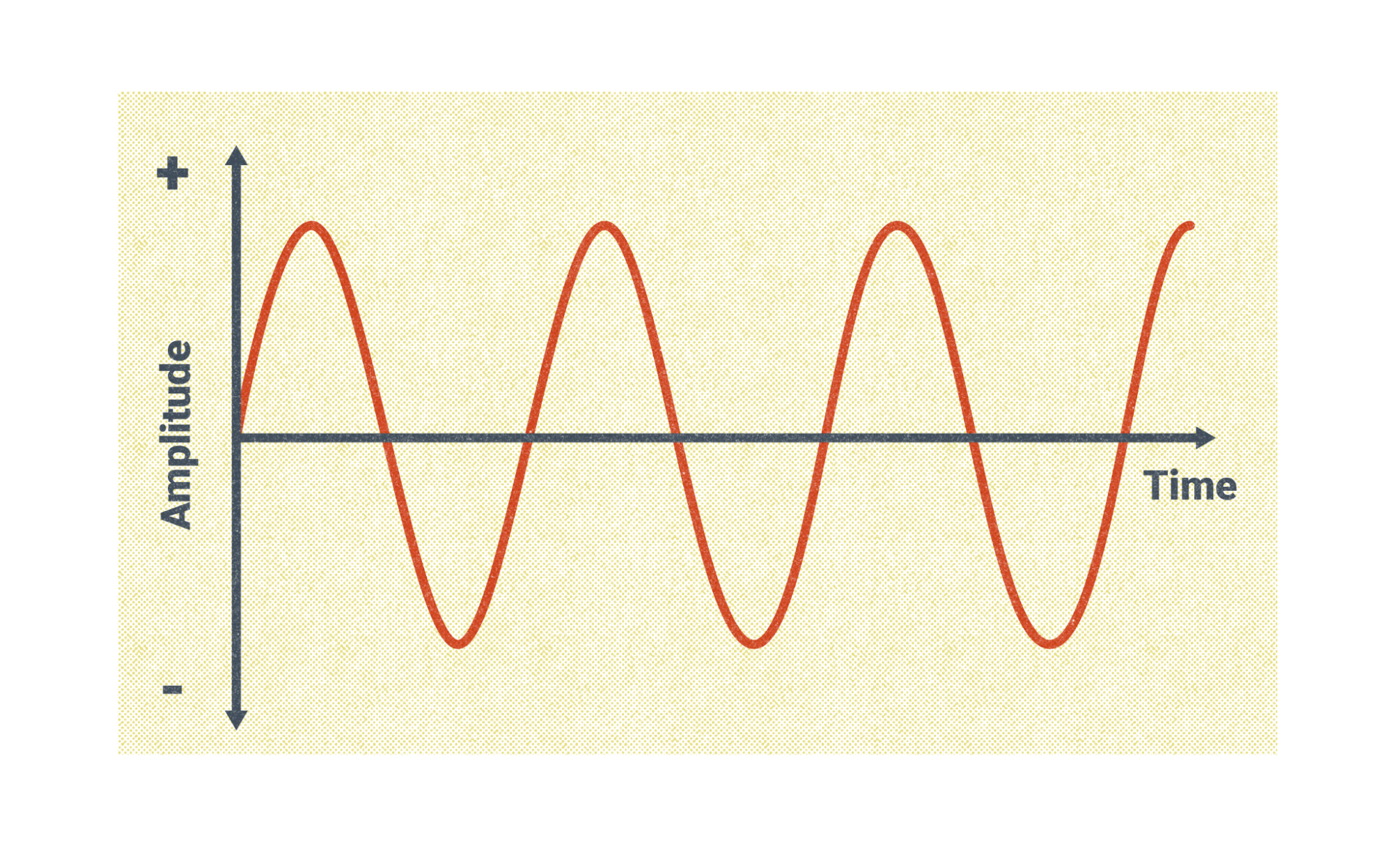
The original AC wave for GTAW was a sine wave. For a brief second, the sine wave passes through zero, and this can cause the arc to break or stutter. This produces a smooth arc that is good for welding but does require continuous high frequency to maintain the arc stability. By adding high frequency, the amount of time the arc is at zero is reduced to almost nothing.
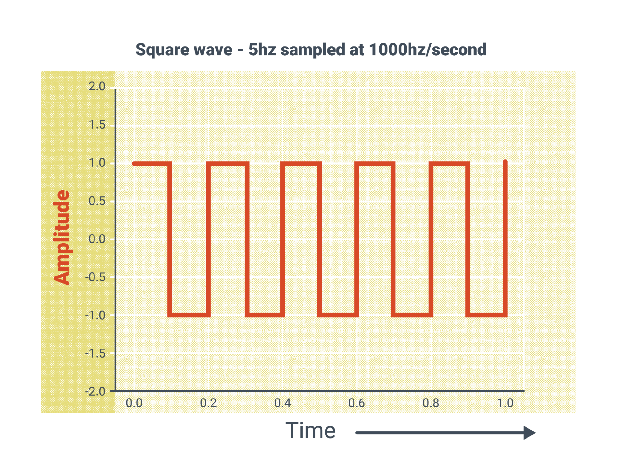
With the technology of inverter machines, the square wave was developed. Square wave switches instantaneously from reverse to straight polarity without spending any time at zero amperage. This removes the need for continuous high frequency and increases the heat input, allowing for faster travel speeds.
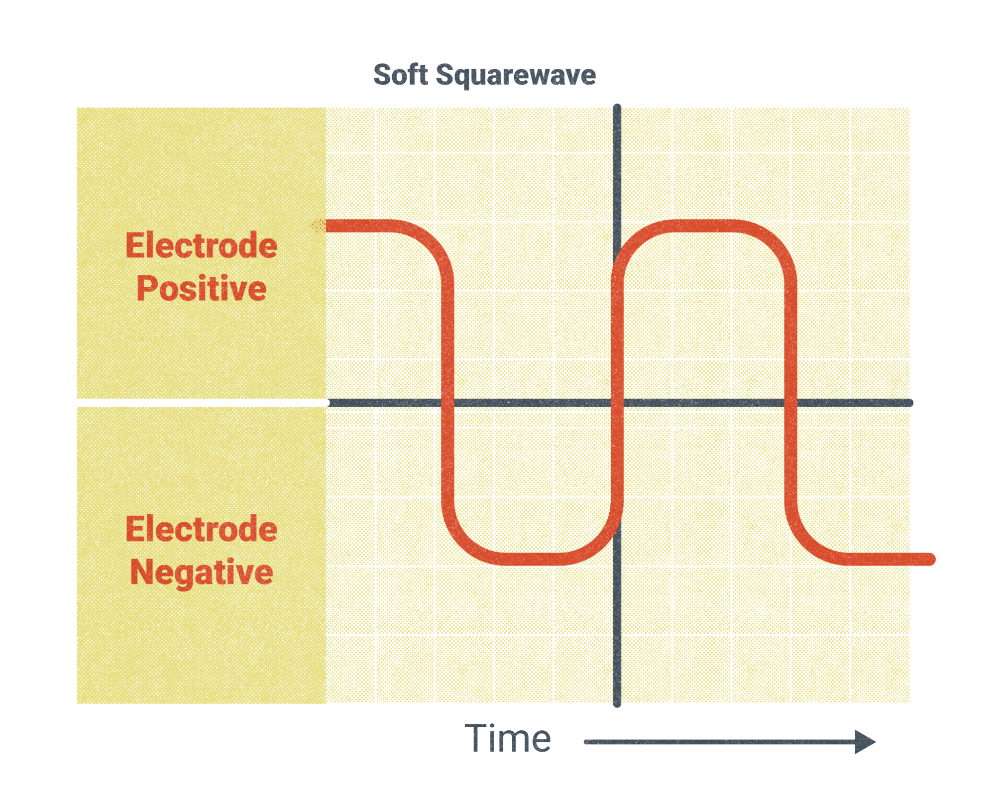
A soft square wave is a mix between the sine wave and the square wave, bringing the benefits of both. This is a good standard waveform for most AC welding.
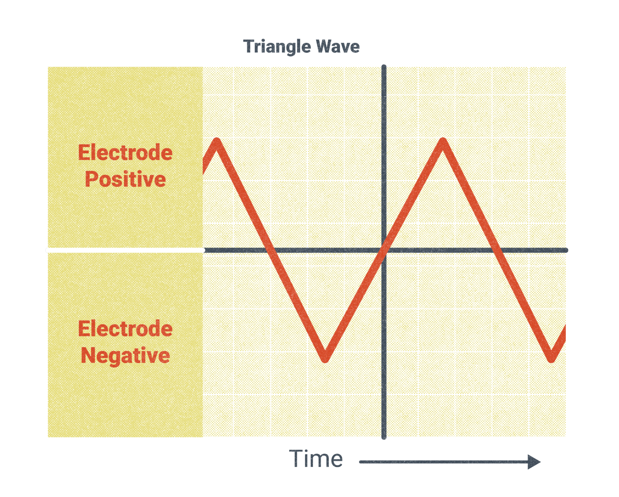
Finally, a triangle wave is used for reducing the heat on the base metal. This is a great waveform for working on thin materials to reduce distortion.
Torches
The torch is a critical tool in GTAW. They are designed to conduct the welding current and carry the inert gas to the weld zone. Torches are cooled by either air or water. Air-cooled touches are typically used for lighter gauge materials requiring less amperage. Water-cooled torches will typically have an amperage rating of over 200 amps. Water is pumped in from a cooler to cool the torch, and as it travels back it cools the lead as well. It’s very important to maintain the water in the cooler to prevent overheating. See the owner’s manual on the machine you use for details.
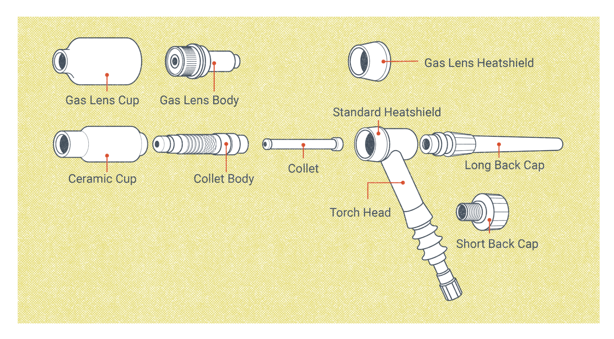
Most GTAW torches are going to be relatively the same, though they do come in a variation of sizes. Let’s cover the basic parts of the torch and what they do.
- Backing cap: This pushes the collet forward and caps the back of the torch. The interior of this cap is hollow to allow room for the excess tungsten.
- O-ring: The O-ring seals the backing cap to the torch body to ensure there is no gas leakage and a vacuum is not created, which would pull in the atmosphere to the weld zone.
- Electrode: Tungsten electrodes come in a variety of sizes and alloys. This will be the most commonly altered, replaced, or sharpened piece of your torch. If at any time the electrode becomes contaminated, you should address it immediately before continuing with welding.
- Collet: As the backing cap is tightened the collet is pushed forward, locking the tungsten electrode in place.
- Torch head/body: The whip for your gas, current, and water (if water-cooled) come together at the handle. The back cap, electrode, and collet are secured on the back while the collet body and nozzle go on the front of the torch body.
- Collet body or gas lens body: The collet body is attached to the front of the torch body. It’s important to make sure you tighten this piece before securing the backing cap to avoid creating a vacuum in the torch, which would lead to contamination in the weld. Gas lenses are an alternative that can be used in place of this part—they are diffusers that create a laminar flow of gas. Their advantage is you get a more even gas coverage with less likelihood of contamination. This also enables you to extend your tungsten slightly farther out of your nozzle/cup.
- Nozzle/cup: Torch nozzles direct the argon or helium shielding gas to the area in which you are welding. They come in an assortment of sizes. Their numbers represent one-sixteenth of the exit diameter. For instance, a number 5 nozzle has an exit diameter of five sixteenths (0.3125) of an inch. A good rule of thumb for how far your electrode can stick out is to make it equal to your exit diameter.
Regulators and Flow Meters
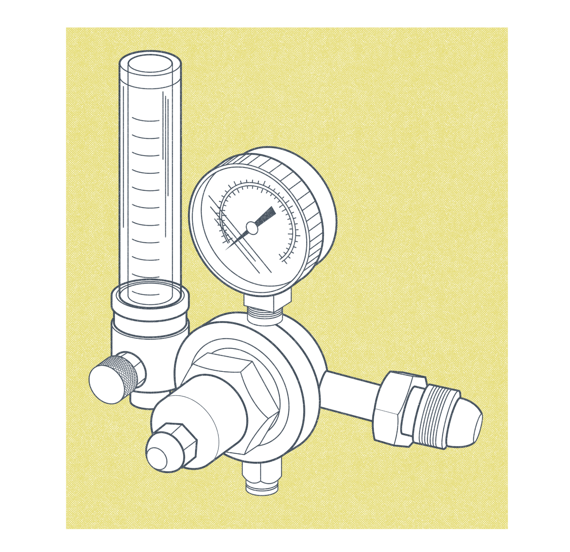
Regulator and flow meter combinations will be most commonly used in GTAW. The regulator shows how much pressure is in the high-pressure bottle and has a set pressure on the flow meter for a consistent flow of shielding gas. The flow meter will control the amount of gas flowing in cubic feet per hour (CFH).
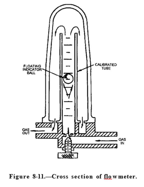
As Figure 11.10 depicts, the gasses flow in and float a ball in a plastic or glass tube and then filter out of the welding machine or directly to the torch, depending on the set up you are running. You take the reading on how gas is flowing from the top of the ball. This can be adjusted depending on the requirements of what you are welding. It’s very important to ensure the flow meter is positioned at 90 degrees to ensure an accurate reading.
Shielding Gasses
It is very important to understand the dynamics of the shielding gasses used in GTAW. Two inert (non-reactive) gasses—argon and helium, or a mixture of the two—are used to protect the molten weld pool and tungsten during welding.
Argon is by far the most commonly used gas in GTAW for its cost and availability. The weight of argon is 39.948 atomic mass units (amu) per mole, making it heavier than air. This means it helps create a blanket over a flat weld to protect it from contamination. Argon also helps produce a very smooth arc.
Helium was the first inert gas used for GTAW but is now less commonly used because of its cost. The need for a higher flow rate when using helium also increases the cost. The atomic weight of helium is 4.0026 amu, making it much lighter than air so it will not pool in a valley when welding in the flat position. The advantages of welding with helium are a hotter arc creating deeper penetration and faster welding speeds. Using a shielding gas that is lighter than air also makes it good for overhead welding.
Regardless of the gas used, your flow rate should be set to protect your molten puddle. You do not want to turn your flow rate up too high, as this can cause turbulence and lead to contamination. A good range to stay in is 11–25 cubic feet per minute. The smaller your nozzle, the less gas you will need.
Setting Up the Welding System
First and foremost, always read the owner’s manual for your welding system. It will have detailed instructions that are specific to your machine.
The first thing you ought to check is the power to the machine. Is it three-phase or single-phase, 110V, 220V, or 480V? Most of the time this information will be labeled directly on the machine.
The next step is to connect your grounding conductor. Depending on your machine, this will either go in the positive terminal or the terminal labeled ground. Then connect your whip to the negative terminal and attach your torch.
Next you connect the shielding gas to the back of your machine if it has a solenoid. If not, there are options to connect the gas directly to your torch, which will need an off valve. Don’t forget to turn the gasses off after every weld.
Specific Safety Considerations for GTAW
When setting up the GTAW welding system, there are some important safety considerations to be mindful of.
- Electric shock: Always insulate yourself from electric shock. Make sure your gloves and clothing are dry. Electricity will follow the easiest path—make sure you are not part of that path.
- High frequency: This has been known to ruin electronics, especially cell phones and pacemakers, in the weld booth. Be very mindful of electronics in the vicinity and do your research.
- Radioactive dust from thoriated tungsten: When sharpened by grinding, thoriated tungsten will produce radioactive dust. Follow the precautions on the safety data sheet for the project, which will likely include but are not limited to avoiding ingesting the dust, washing hands after handling, and wearing a mask that covers the nose and mouth.
- Hexavalent chromium: This is a cancer-causing fume that is produced during the hot work of welding chromium-containing alloys (mostly stainless steel). Welding with GTAW is going to result in lower exposure than other processes, but a respirator with properly rated filters is highly recommended.
- Burns: With GTAW, you are elevating the metal to extreme temperatures. This makes burns the most common injury in welding. Always wear your PPE and be aware of your surroundings. And if it hurts while welding, that’s a sign you must stop.
- Ultraviolet and infrared rays: These rays can cause burns and irritation to the skin and eyes. Cover all skin and never expose your eyes to the arc. At minimum use a shade 9 on your helmet when welding, and if you are having trouble seeing, go darker before you go lighter.
- Argon: Argon may pose a health risk. Exposure to high levels of the gas can cause nausea, vomiting, unconsciousness, coma, and death. No occupational exposure limits have been established for argon. Always follow safe work practices when working with this shielding gas (New Jersey Department of Health, 2016).
Attributions
- Figure 11.4: AC Sine Wave by Nicholas Malara, for WA Open ProfTech, © SBCTC, CC BY 4.0
- Figure 11.5: AC Square Wave by Nicholas Malara, for WA Open ProfTech, © SBCTC, CC BY 4.0
- Figure 11.6: AC Soft Square Wave by Nicholas Malara, for WA Open ProfTech, © SBCTC, CC BY 4.0
- Figure 11.7: Triangle Wave by Nicholas Malara, for WA Open ProfTech, © SBCTC, CC BY 4.0
- Figure 11.8: GTAW Torch Exploded View by Nicholas Malara, for WA Open ProfTech, © SBCTC, CC BY 4.0
- Figure 11.9: Combination regulator and flowmeter by Nicholas Malara, for WA Open ProfTech, © SBCTC, CC BY 4.0
- Figure 11.10: Cross section of flowmeter by Naval Education and Training Professional Development and Technology Center in the Public Domain; United States government work
