7 Destructive Examination
Basics of Destructive Examination
Destructive examination involves the destruction of a weldment to determine its mechanical properties and/or visually inspect a cross sectional area of the weld. To imagine what a cross sectional is, think of cutting a pipe in half. The exposed area of the pipe wall where you made your cut is the cross sectional area. Some of us cut better than others; just think of the first time you torch cut something. For destructive examination the cuts are made as precisely as possible using an accurate cutting method and preparation of the surface to ensure that it is smooth for easier identification of discontinuities. See Figure 19.49 and Figure 19.49 for examples of surfaces that have been prepared for examination using macroetching where an acid is used to prepare the cross sectional surface of a weld to see the grains and heat affected zone of a weld.
Uses of Destructive Examination
Destructive examinations allow an inspector or fabricator to see what the inside of a weld looks like. Because destructive tests destroy the weldment, destructive tests are only performed on weldments made for qualification purposes. This qualification can be for a welding procedure, a filler metal, a welder qualification, or other qualification/inspection.
Whenever you perform a code weld, everything from the filler metal, base metal, welding process, welding machine settings, and the welding technique are all qualified and listed on the Welding Procedure Specification (WPS) (See Chapter 18: Welding Procedure Specifications). Filler metals, base metals and welds are destructively tested using bend tests, tensile tests, and Charpy V-notch tests depending upon the code requirements for qualifying a welding procedure which are discussed in the following sections.
Bend Tests
Bend tests do exactly what their name implies. Welds on plates or pipes are cut in accordance with the welding code that is being used. The code will specify the dimensions of the bend test specimens along with the dimensions of the bend testing machine. An example bend testing machine is shown in Figure 19.39 below.
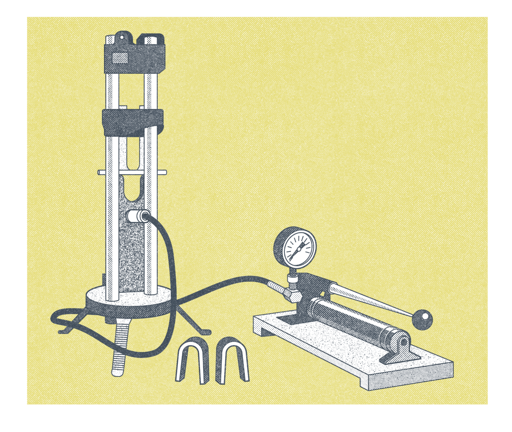
The machine in Figure 19.39 is a mechanical type machine where the operator would have to use the lever to pump air pressure into the machine to apply a force down on the specimen to bend it. If you look closely at Figure 19.39 you can see the straight metal specimen before it is bent sticking out from the sides of the taller portion of the machine with the plunger. Figure 19.39 also shows two bend specimens in the shape of upside down “U”s at the bottom of the Figure in the middle. Actual bend test specimens are shown below in Figure 19.41. Bend tests look at how well the welds are fused to each other and if the metal is solid throughout without any defects. Defects are discontinuities such as tears, slag inclusions, and porosity, that are larger than the acceptable sizes listed in the applicable code.
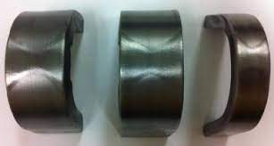
Figure 19.41 shows bend specimens of a double vee groove weld. The two welds can be seen in each of the specimens. The inspector will look for fusion of weld passes to each other and to the base material. Slag inclusions, which are pieces of slag in the weld, will be looked for in weld tests using processes that have slag such as SMAW and FCAW. Tungsten inclusions would be looked for if GTAW or Plasma Arc Welding (PAW) were used. PAW is not discussed in this book, but it is worth mentioning that that process also uses a tungsten electrode. Each code will specify what the acceptable size and/or number of discontinuities can exist in a specimen. Codes also specify any follow on steps if a bend test fails. In some cases additional bend test specimens may be used as specified in the code being used. In other cases the weld test will need to be redone and new samples tested if the bend test fails.
Tensile Tests
Tensile tests measure the tensile strength of a portion of the weldment. For filler metal test specimens the entire sample is typically only weld metal as specified in the code the filler metal is being tested to. For test specimens that are used to qualify welding procedures or welders, those samples include both base metal and filler metal. Figure 19.42 shows a test plate and the locations where test specimens are cut from the test plate based on AWS D1.5 Bridge Welding. Structural code tests are similar for our discussion.
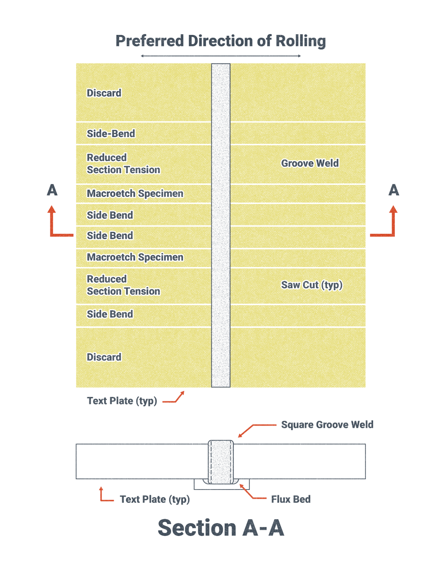
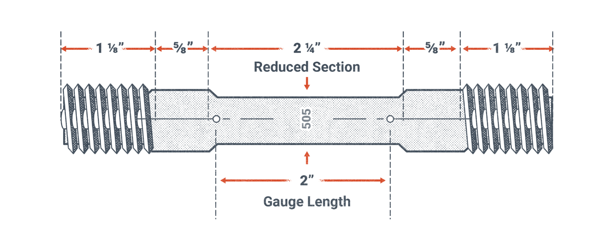
Figure 19.42 shows locations of test specimens that are taken from a test plate. Those specimens are machined to dimensions as specified by the code being used. Figure 19.42 and 19.43 show test specimens that have threads on the ends for placement in a tensile testing machine. The dimensions and tolerances of the specimen ensure consistent tests and tests which are designed to fail in the reduced section.
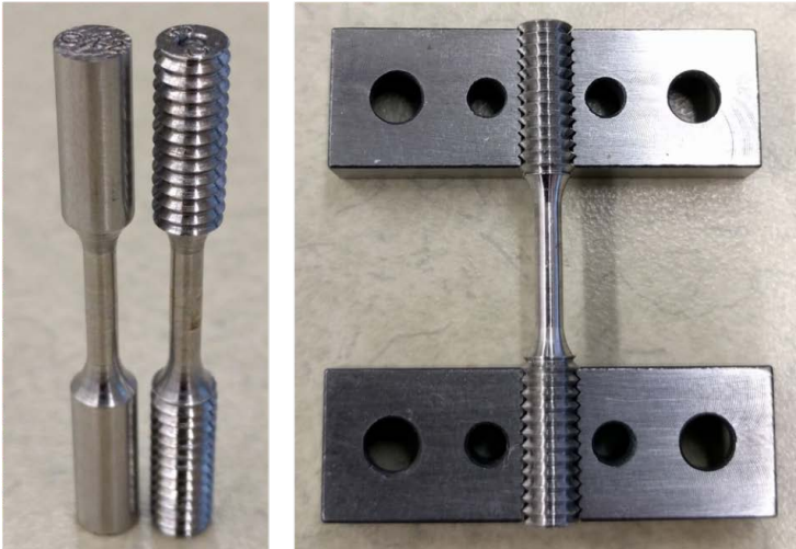
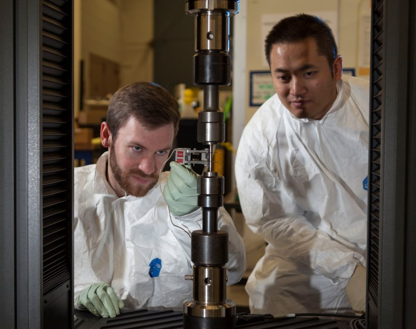
A tensile test machine is shown in Figure 19.44 with the test specimen in the center. The technician on our left looking at the Figure is holding a strain gauge. A strain gauge measures the change in length of the specimen and using the original length before a load was applied can calculate the strain which equals the change in length divided by the original length. The strain gauge is removed from the specimen before the specimen breaks. A computer system is typically used to collect the data from the test setup. The computer program, using the material properties of the specimen’s material, and the data from the test in progress will typically alert the technician to remove the strain gauge. This is done because a strain gauge is an expensive piece of equipment.
The results of the tensile test are compared to the requirements of the code that the test is being performed to. If the test results are within the ranges specified in the code being used, the tests pass.
Charpy V-Notch Tests
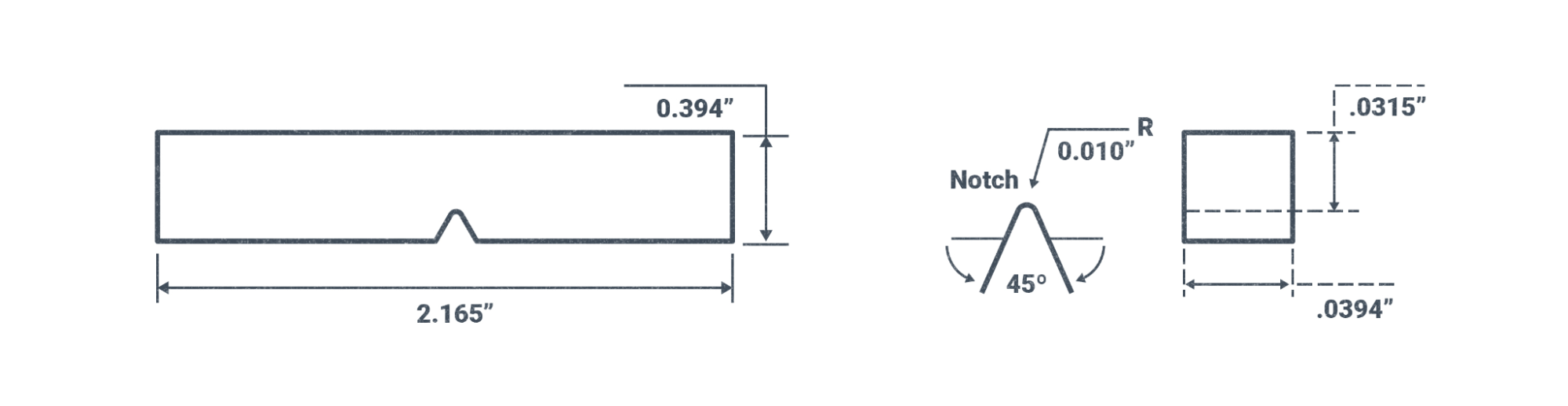
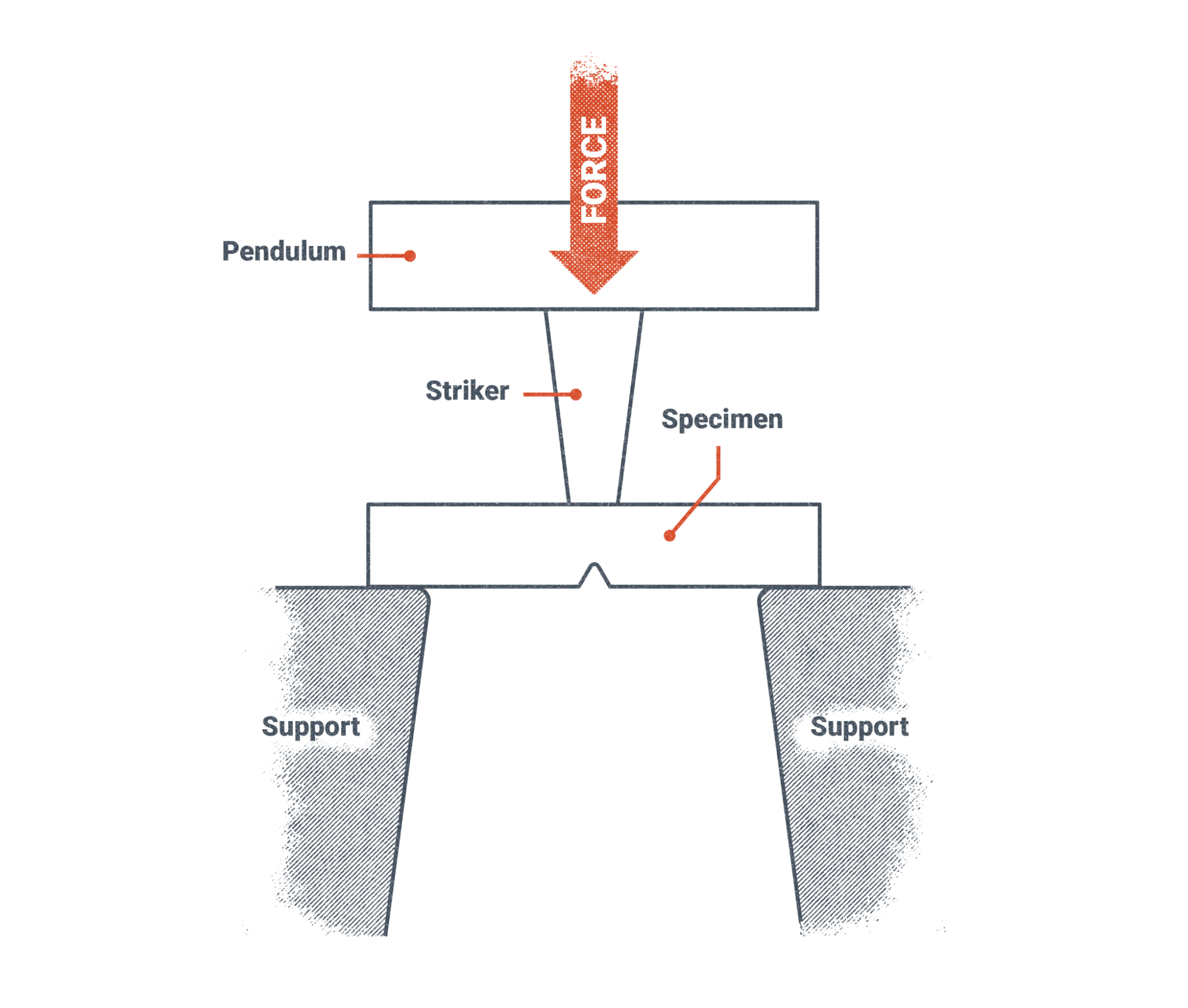
Charpy V-Notch tests measure the energy that is absorbed by a test specimen with a “V notch” in it. A hammer is raised to a specific height and is then released to impact the specimen. The mass (commonly referred to as weight) of the hammer and its height when it is swung towards the specimen, determine the energy of the hammer at impact.
The specimen absorbs some energy and the rest of the energy is used by the hammer to travel past the specimen and continue on its arc of travel until it reaches a maximum height. The machine will record the maximum height of the hammer post impact which is used to calculate the energy absorbed by the specimen.
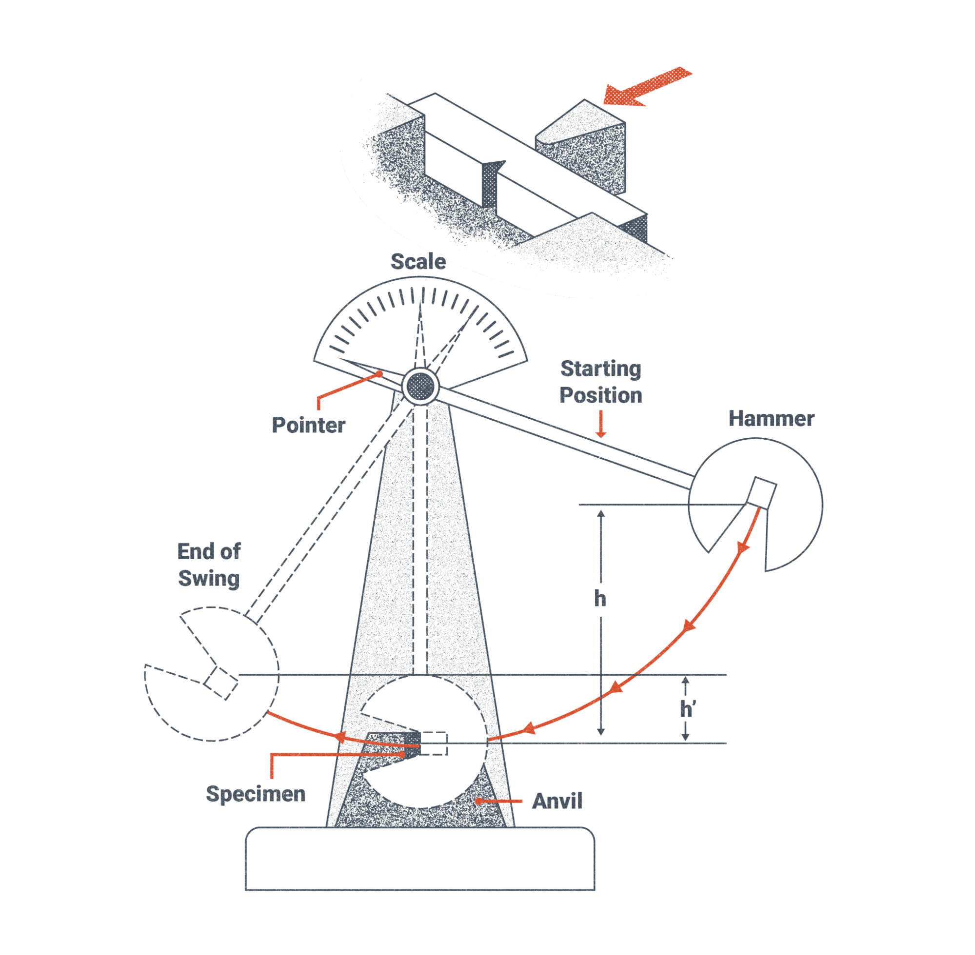
Figure 19.48, below, is an overhead view of the pendulum in Figure 19.45 above. In Figure 19.47 the force of the hammer, or striker as labeled, strikes the specimen opposite of the v-notch. The v-notch provides a weak point where failure of the specimen will occur. Similar to the tensile and bend tests, the Charpy V-Notch tests have requirements in the code being used from the dimensions of the test specimen, specifications for the testing machine, temperatures of the test specimen, and a required range of energy that must be absorbed by the specimen in order for it to pass the test. Materials that can not absorb the specified energy in the standard, are not as strong as they need to be and are at higher risk of failure when the fabrication is subjected to loads.
The successful and thorough fusion of the welds measured in the bend tests, along with the measurement of the tensile strength of the weld using the tensile test, and the tests of the energy that is absorbed by the weld all provide required information about the mechanical properties of the welds that are required for qualification of welding filler metals, welding procedures, and welders and welding operators. The requirements of the tests are specified in the codes being used.
Etching Exposed Surfaces for Visual Inspection
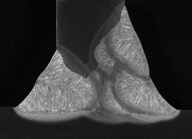
Etching is a destructive test that is used to expose the detail of a cross section of a weld. Figure 19.48 below shows the cross section of a T-Joint. To help visualize the cross section of the weld, imagine welding a T-joint and then cutting the T-Joint in the middle. If you look at the cut surface it resembles a T. That T shape is the cross section of the T-Joint. After the cut is made, the surface is prepared so that it is smooth and an acid is applied to the surface to bring out the detail of the metal grain structure.
In Figure 19.49 you can see the individual weld beads and the heat affected zones of each weld bead. The grain structure can also be seen in the individual weld beads. Figure 19.48 is an excellent high quality example of an acid etch test.
Due to acid etch tests using acids care must be taken when handling acids and acid solutions. Never use acids without permission from your instructor and follow the instructions and precautions on the acid container.
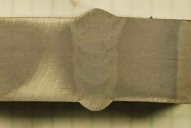
Figure 19.49 is a picture of an acid etch of a butt joint and how it would appear in normal lighting. The individual weld beads are visible, however the grains within the weld are not readily visible.
Attributions
- Figure 19.39: Bend Test Machine by Nicholas Malara, for WA Open ProfTech, © SBCTC, CC BY 4.0
- Figure 19.40: Weldability by U.S. Department of Energy, Advanced Reactor Concepts Program in the Public Domain; United States government work
- Figure 19.41: Test Specimen Locations by Nicholas Malara, for WA Open ProfTech, © SBCTC, CC BY 4.0
- Figure 19.42: Standard Tensile Test Specimen by Nicholas Malara, for WA Open ProfTech, © SBCTC, CC BY 4.0
- Figure 19.43: Left: picture of specimens after machining, Right: a specimen fit to grips by U.S. Department of Commerce, National Institute of Standards and Technology in the Public Domain; United States government work
- Figure 19.44: Aaron Bales, left, and Rob Panaro attach an extensometer to a tensile specimen. The extensometer gives an accurate measure of how much the specimen stretches during a tensile test. by U.S. Department of Energy, National Nuclear Security Administration in the Public Domain; United States government work
- Figure 19.45: Charpy Test Specimen Dimensions by Nicholas Malara, for WA Open ProfTech, © SBCTC, CC BY 4.0
- Figure 19.46: Charpy V-Notch Test Machine by Nicholas Malara, for WA Open ProfTech, © SBCTC, CC BY 4.0
- Figure 19.47: Charpy Test Diagram by Nicholas Malara, for WA Open ProfTech, © SBCTC, CC BY 4.0
- Figure 19.48: Example macroetch of a T-joint mockup by U.S. Department of Transportation, Federal Highway Administration in the Public Domain; United States government work
- Figure 19.49: Commercial ER100 weld wire by U.S. Department of Energy, Oak Ridge National Laboratory in the Public Domain; United States government work
CK Worldwide. (2019, February). The standard in TIG welding. https://www.ckworldwide.com/asset/5f3c5cb0204e9
Jefferson, T. B. & Woods, G. (2015). Metals and how to weld them (Second edition). Welding Engineer Publications, Inc.
Midwest Tungsten Service. (n.d.). TIG welding tungsten electrode selection chart. https://www.tungsten.com/blog/tig-welding-tungsten-electrode-selection-chart
Navy, U. (2019). Steelworker (Vol. 1).
New Jersey Department of Health (2016, August). Argon: Hazardous substance fact sheet. https://www.nj.gov/health/eoh/rtkweb/documents/fs/0151.pdf
Russell, M. (1941). (Serial No. 373,157). U.S. Patent and Trademark Office. https://patentimages.storage.googleapis.com/c2/c5/3f/8ebcd548700da1/US2274631.pdf
SkillsCommons Repository. (2015). AWS electrode classification for gas metal arc welding and gas tungsten arc welding (GMAW and GTAW). https://www.skillscommons.org/handle/taaccct/2193
FCAW Welding Fundamentals
The fundamentals of FCAW are about the same as those for other arc welding processes:
- Electrical characteristics (current, voltage, and polarity)
- Electrical stickout
- Work and travel angle
- Travel speed
- Electrode manipulation
Electrical characteristics will be recommended by the electrode manufacturer and controlled by the welding procedure specification. The required polarity for an electrode must be used, but welding current and voltage will be recommended as a range and there is room for adjustment. Where you set the machine within this range is really a function of base metal thickness: Thicker base metals will require higher electrical settings, which increase the heat of the welding arc. Remember, there is no direct way to control welding amperage. Rather, amperage is determined by wire feed speed and electrode diameter, with larger electrodes and higher speeds resulting in high welding amperage. At all times you should remain within the range recommended by the manufacturer or required by the welding procedure.
As we’ve already covered, it is critical that the proper stickout is maintained as the electrode is moved down the joint. This takes practice to get used to, so don’t get discouraged. Keeping your head in a good position is helpful in maintaining proper stickout—if your head is positioned directly behind, or nearly behind, the welding gun, it is difficult or impossible to see the amount of stickout. Instead, find a comfortable position where your head can be on one side of the welding gun and you can see, and therefore monitor, the amount of electrical stickout during welding.
The work and travel angles of the electrode influence where the heat of the arc is directed and the shape of the finished weld bead. Electrode angles are not controlled for in welding procedures and are left up to the discretion of the welder. Selecting the proper angle and maintaining it throughout welding is a practiced skill.
Travel angle is the angle of the electrode relative to the length of the weld joint. Guidance for the travel angle in FCAW is rather straightforward: a pulling or dragging angle of 10–30 degrees should be used. A common saying among welders engaged in welding processes that produce slag is “if there’s slag, you drag”, as it speaks to a problem with pushing these types of electrodes. If FCAW electrodes are pushed along the joint, there is a strong chance a ball of slag will be pushed in front of the weld puddle resulting in a slag inclusion at the root of the weld bead. The one notable exception to this rule is when welding in the vertical position with an upward progression—in this case, a slight push angle of 10–15 degrees should be used.
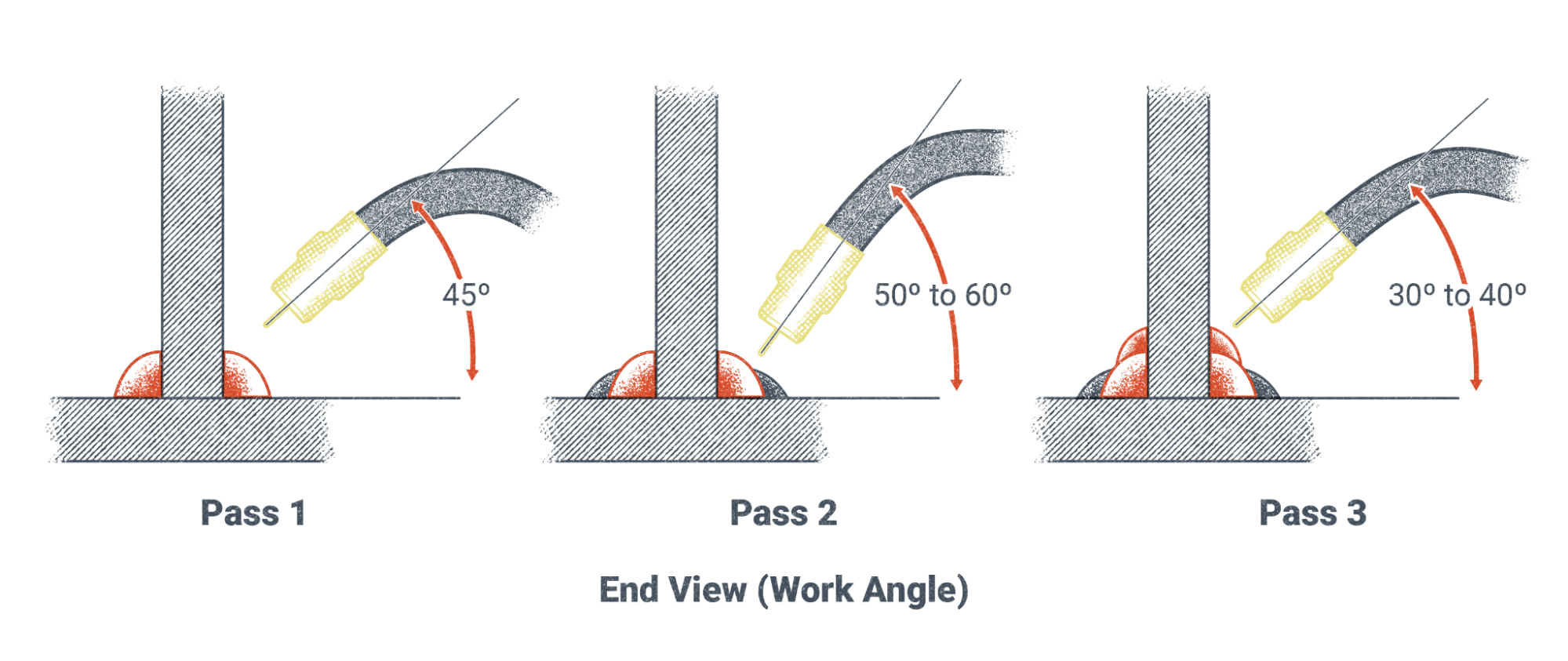
Work angle, the angle of the electrode relative to a cross-section of the joint, is a more complicated matter. The exact work angle used in FCAW is a matter of how the joint is designed and where the welder would like to direct the heat of the arc and deposited weld metal. In multi-pass welds the work angle of each weld pass may be different in order to properly fuse each pass and achieve the correct weld size. Take the example below of a three-pass fillet weld in a T joint:
- A 45-degree work angle is used in the first pass to direct the heat and weld metal straight into the joint root.
- In the second pass, a higher work angle of 60-degree is used to ensure proper fusion to the weld bead and base metal below.
- For the third pass, a lower work angle of about 30-degree is used to help push the weld deposit upward and give the vertical leg of the weld its proper height.
Travel speed, another fundamental of FCAW, is the speed the electrode progresses along the joint. Travel speed in FCAW, as well as GMAW, is significantly faster than SMAW or GTAW processes. This can present a challenge for welders when they are learning the process. Too slow a travel speed can result in overlap and an overly convex weld. Too fast a travel speed can leave undercut, lack of proper fusion, and an undersized weld. Travel speed is an essential variable recommended by the manufacturer and controlled by the welding procedure specification (WPS). The proper travel speed for FCAW electrodes typically ranges from 8–12 inches per minute, but you should always consult the electrode manufacturer’s recommendations or the proper WPS to ensure successful welding.
Finally, electrode manipulation can be used to increase the size or width of an individual weld bead and can be helpful in controlling the heat of the welding puddle. Because FCAW has a high deposition rate and large-diameter electrodes are available, a stringer bead is often sufficient, especially in the flat position. However, when welding with a smaller electrode or in any position other than flat, a weaving technique can be favorable. Small oscillating motions (back and forth) along the path of the weld joint can also help increase bead size and thickness. Even when a stringer bead is sufficient, putting small repetitive motions into the electrode can help you get into a rhythm, which also helps you maintain a consistent travel speed.
Attributions
- Figure 9.15: Work Angle by Nicholas Malara, for WA Open ProfTech, © SBCTC, CC BY 4.0
Overview
In today’s industries, the ability to produce quality welds quickly is vital. Whether you are planning to weld thin sheet steel for an automobile restoration, a 2-inch-thick lug on a bulldozer, or a new winch on the deck of an aluminum fishing boat, gas metal arc welding (GMAW) has a great deal of versatility.
GMAW can weld thin sheets, thick plate, pipes, as well as many other items. It can be used to weld many materials, including steel, stainless steel, aluminum, magnesium, copper alloys, nickel alloys, titanium alloys, and others. Its multitude of applications is vast and, therefore, makes learning this process a valuable asset to any welder’s skill set. As you explore GMAW further in this chapter, you will learn more about its equipment, functionality, and limits.
Objectives
After completing this chapter, students will be able to:
- List the uses of the GMAW in industry.
- Identify equipment associated with GMAW.
- Recall techniques and variables for setting up and using GMAW.
- Define the different modes of transfer associated with GMAW.
- Name shielding gasses used for GMAW.
- Identify GMAW consumables.
- Recall basic troubleshooting for GMAW.
Key Terms
- Buried arc
- Metal inert gas (MIG)
- Metal active gas (MAG)
- Globular transfer mode
- Gun securing knob
- Pressure adjustment knob
- Pulsed spray transfer mode
- Short circuit transfer mode
- Spray transfer mode
- Transfer mode
- Transition current
- Wire-feed speed (WFS)
Attributions
- Chapter opening image: Migpipe by Weldscientist is released under CC BY-SA 4.0
