5 Non-Destructive Examination
Basics of Nondestructive Examination
Nondestructive examination describes a set of examination techniques that do not destroy the fabrication being inspected. Destructive tests provide information such as the tensile and yield strength of a weld that can not be determined by nondestructive tests. However if we only performed destructive tests on our weldment, we wouldn’t have any fabrications to place in-service because they would all be destroyed. The basic premise of a nondestructive test is to provide the inspector with information about the quality of the weldment without damaging or altering the weldment.
Uses of Nondestructive Examination in industry today
As a welder in school learning to weld, you visually inspect your welds and your classmates’ welds all the time; whenever you get a chance. It is highly recommended as a welder learning to weld that you take pictures of your welds each week so you can see the progress you have made with time.
In industry, especially at fabrication shops with quality assurance programs, there will be a weld sample board with examples for welders to see of what acceptable and unacceptable welds look like. The purpose of these examples is to not only provide you with a means to determine if you are doing a good job welding, but to also provide an example weld to strive for so your welds meet a minimum quality standard that will more likely pass the official quality inspection.
Inspectors, such as American Welding Society (AWS) Certified Welding Inspectors (CWI) will examine your welds using the Nondestructive Examination (NDE) techniques described in this chapter. It is important to note that NDE and Nondestructive Testing (NDT) are terms that are commonly used interchangeably but they have different meanings. NDT refers to the testing itself, while NDE refers to the testing and the interpretation of the results.
The more critical the application of your weldment, the more stringent the inspection requirements will be depending on the code used. NDE is used by industry to ensure that quality weldments are being made to meet both safety and quality requirements and expectations that customers have. Let’s discuss some of the more common NDE methods used by industry.
Visual Inspection (VT)
Visual inspection (VT) is the most common inspection method used today because it is relatively easy to do and welders and inspectors are expected to have a minimum level of visual acuity, meaning the ability to see minor details, to inspect their welds. Visual discontinuities that visual inspection is intended to find are:
- overlap
- porosity
- slag inclusions
- cracks, such as crater cracks
- spatter
- arc strikes
The list of discontinuities above are common discontinuities found on or near welds. A discontinuity becomes a defect if its size or number of occurrences exceeds the criteria in a welding code or standard being used for inspection.
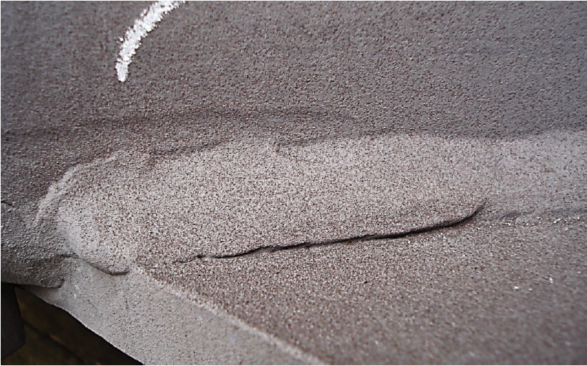
Overlap
Figure 19.1 below shows an example of overlap. Overlap occurs when the molten weld pool does not fuse into the base material. The weld pool falls on top of the base material and is not solidly connected to it. Other terms used for overlap are cold roll and cold lap.
Porosity
Porosity occurs when gasses produced during welding can not escape the molten weld pool before it solidifies. The gas occupies volume that the solidifying weld pool can not occupy. If the welding process involves slag, the slag could be what blocked the gas from escaping. Figure 18.2 shows an example of porosity in a solidified weld bead.
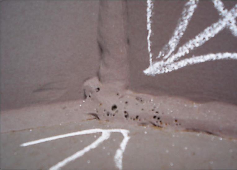
Welding codes for steel will typically not allow porosity or limit it to a low number of pores for welder qualification tests. Aluminum, by nature of the process, has more porosity than steel. Porosity weakens the weld because there isn’t solid material to take up the load applied to the weldment. Fortunately, porosity is circular or rounded, which means that each pore will not create a devastating stress riser by itself.
Stress risers are areas where lines of stress concentrate. If too much stress exists in one area, the yield strength of the material may be exceeded which will cause plastic deformation of the material and possible failure of the weldment.
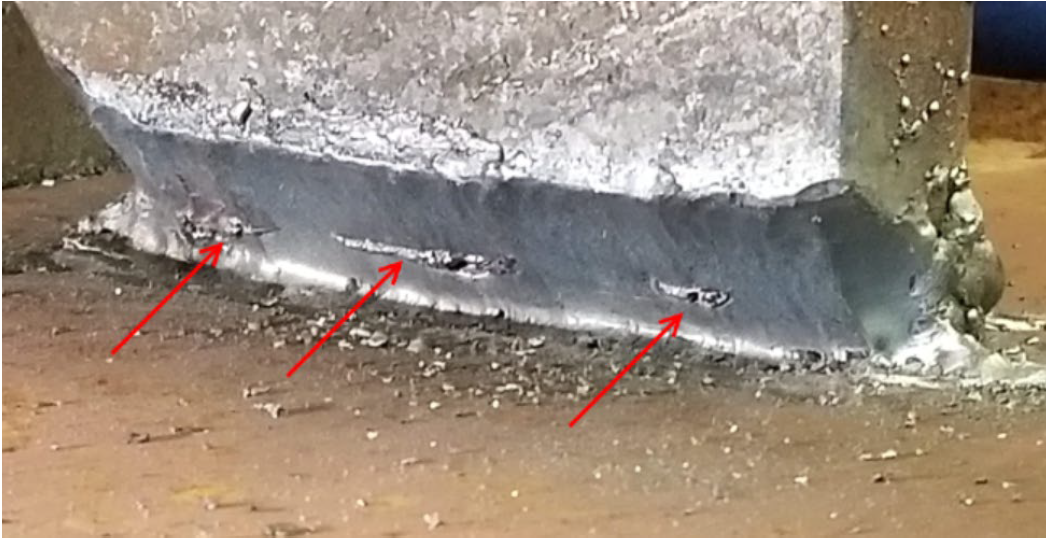
Slag Inclusions
Slag is a very important piece of the welding processes that form slag. Slag forms when certain elements in the fluxes of the consumables react with elements in the weld that are impurities that must be removed to ensure a quality weld. The designers of the consumables, whether that be the flux coatings on Shielded Metal Arc Welding (SMAW) electrodes, the flux within Flux Cored Arc Welding (FCAW) wires, or even the granular flux used in Submerged Arc Welding (SAW), design the consumable to remove impurities. Gas Metal Arc Welding (GMAW) and Gas Tungsten Arc Welding (GTAW) are processes that do not produce a slag.
During the design process, if the welds suffered defects during the testing phase of development, the chemistry of the flux would be changed. This change is done much like a baker or cook changes a recipe if the end product doesn’t have the taste, texture, or color desired. The impurities that must be removed bond with the elements in the flux that were added to bond to the impurities, and they float to the surface of the weld pool to form slag.
Slag not only removes impurities from the weld pool, it also helps control the cooling rate of the weld pool by slowing down how fast the weld pool solidifies. Once a weld bead has been put in place, the slag must be removed by mechanical means before the next weld bead is put in place. This can be done using a chipping hammer, wire brush or a wire wheel for example.
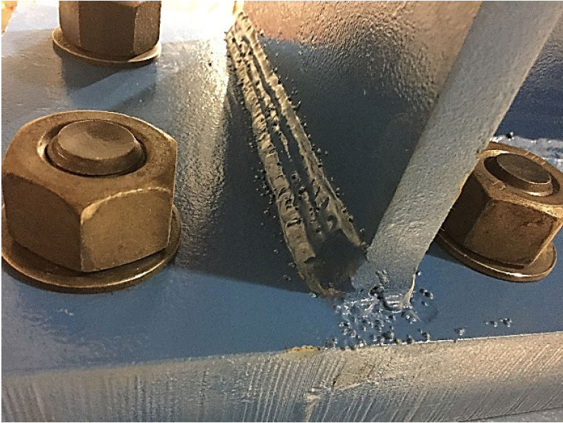
Figure 19.3 below shows slag inclusions that are pointed to with red arrows.
Cracks
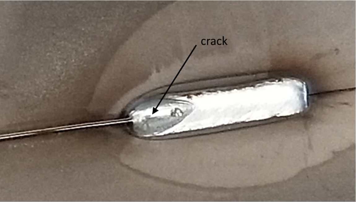
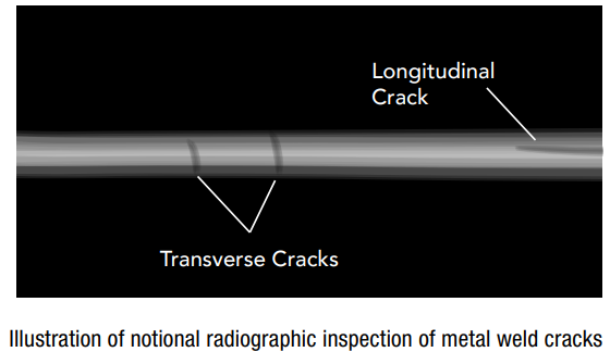
Cracks are never acceptable because they will spread overtime, especially when they are exposed to a cyclical load. When describing cracks in welds, there are generally transverse cracks which occur perpendicular to the direction of travel of the weld bead, longitudinal cracks which occur parallel to the direction of travel of the weld bead, and crater cracks which usually occur in a depression or crater at the end of a weld bead and radiate from the center of the crater out.
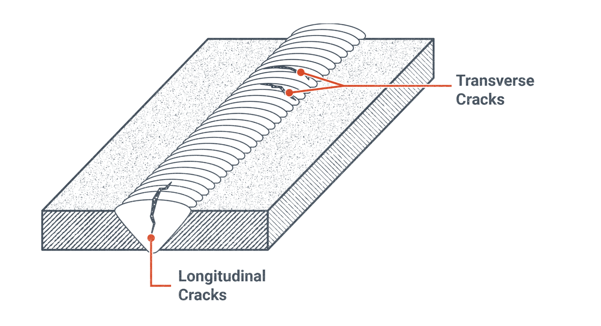
Figure 19.4 shows an illustration of transverse longitudinal cracks, while Figure 19.5 shows an example of a crater crack that typically forms in an aluminum weld bead when a crater is not filled in at the end of a weld bead.
Spatter
Spatter, see Figure 19.6 below, by itself is generally not detrimental to a weldment, however it does show poor workmanship if the welding process used normally doesn’t have spatter. Spatter is usually removed by mechanical means such as with a grinder.
Spatter does interfere with Magnetic Particle Testing and must be removed. Ultrasonic testing, which is discussed later in this chapter, may use a transducer which is slid across the surface of a weldment to send ultrasonic sound waves into the material at a predetermined angle. If spatter exists on the surface of the weldment, the angle of the ultrasonic sound waves would not be correct if the spatter interfered with the placement of the transducer relative to the surface of the weldment being inspected.
If your blueprint shows a welding symbol with MT or UT in the tail, it is best to know whether or not spatter needs to be removed after welding has been performed.
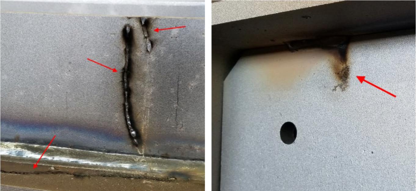
Arc Strikes
When welding, welders should always strike an arc within the weld joint that is being welded. The reason for this is more than just cosmetic or for avoiding poor workmanship. When steels are cooled too quickly, they can form martensite which is brittle.
One discussion that comes up regularly amongst welders is whether quenching mild steel in a quench tank will form martensite. Typically, the amount of base material that exists retains enough heat that your weldment does not form martensite when quenched. However this is not the case when the base material is at room temperature, and a small amount of base material is melted and rapidly cooled following an arc strike. Martensite, depending on the steel, will form a brittle spot which will likely be the location for crack formation. This is why if you ever accidentally arc strike a gas bottle, that bottle is immediately taken out of service, because it could fail. As a welder, if you arc strike outside of the weld joint, your employer or the code may require you to gouge out the arc strike and fill the removed material with a weld.
So why aren’t arc strikes in the weld joint a bad idea? Fortunately, the arc strikes in the weld joint melt when the weld is placed into the joint. The weld will penetrate into the base material by melting and mixing with the base material before solidifying. Any martensite that was formed in the arc strike is destroyed when it melts.
Liquid Penetrant Testing (PT)
Liquid Penetrant Testing (PT) is a multistep process that is used to highlight cracks, porosity, and even arc strikes on a weldment. This method works by applying a very viscous liquid that easily penetrates into the cracks and pores on the surface, which are later highlighted by a developer. Let’s look into this process more thoroughly.
The following general steps are followed when performing liquid penetrant testing:
- Thoroughly clean the surface of the weldment being examined
- Apply the liquid penetrant
- Allow the liquid penetrant to remain for the prescribed dwell time
- Remove the excess liquid penetrant from the surface with carefully cleaning
- Apply the developer
- Wait for any indications to appear through the developer
The steps described above would be performed by a trained and qualified inspector for code inspections. PT is available to the public wishing to perform the tests at home.
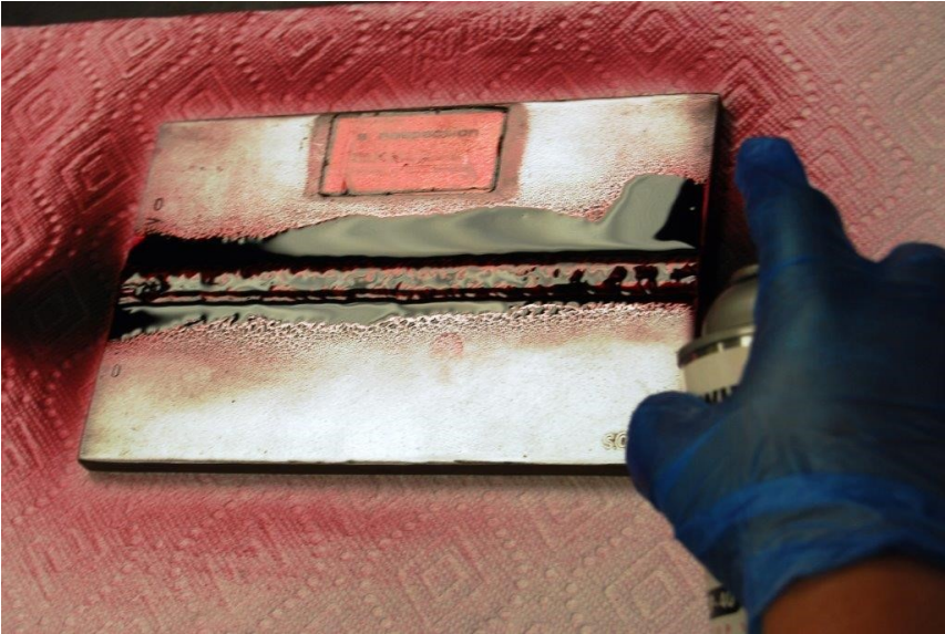
Figure 19.8 above shows the application of liquid penetrant to the weldment being inspected. The viscous liquid flows very easily into tight spaces through capillary action. Capillary action allows liquids to move against the force of gravity in trees from the roots to the top of the tree, or in a kitchen sponge stood on end in a shallow bowl of water. Over time you would see the sponge absorb the water into areas above the top level of the water in the bowl. This is capillary action in action.
Through capillary action and the viscous nature of the liquid penetrant, the penetrant will seep into the cracks and porosity that is exposed to the surface of the weldment. Capillary action is a relatively slow process and the dwell time enables the penetrant enough time to seep into these surface discontinuities.
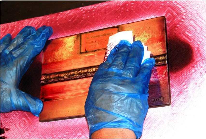
Figure 19.9 above shows the inspector carefully cleaning the excess liquid penetrant from the weldment. It is important to remove the liquid penetrant from the surface so there aren’t any false indications once the developer is put on the surface. Once cleaned, only the liquid penetrant that has seeped into the surface discontinuities will be drawn back out to react with the developer.
Wearing gloves during this process is very important, otherwise the liquid penetrant will seep into your porous skin and stain them. There are likely also other health hazards from liquid penetrant that would be discussed on the Safety Data Sheet (SDS) from the manufacturer of the penetrant.
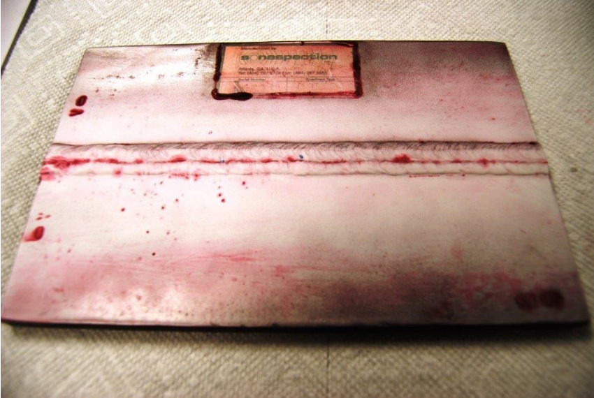
Figure 19.10 shows the developer being applied to the weldment after the surface has been cleaned of any excess penetrant. As an example of this inspection process, Figure 19.10 provides some great indications on the surface of this weldment. The certified liquid penetrant inspector will know what the indications on the surface mean.
For example, it appears that there may be spatter located on the left hand side of the picture below the weld bead. Spatter is a discontinuity but not a defect. If you are performing a liquid penetrant test at home to try it out, it is important to make note of surface features such as spatter so you don’t mistake them for defects later after the developer has reacted with any remaining liquid penetrant.
Additionally, some liquid penetrant may have remained in the lower parts of the weld bead contours. These contours may be acceptable resulting in another set of false indications.
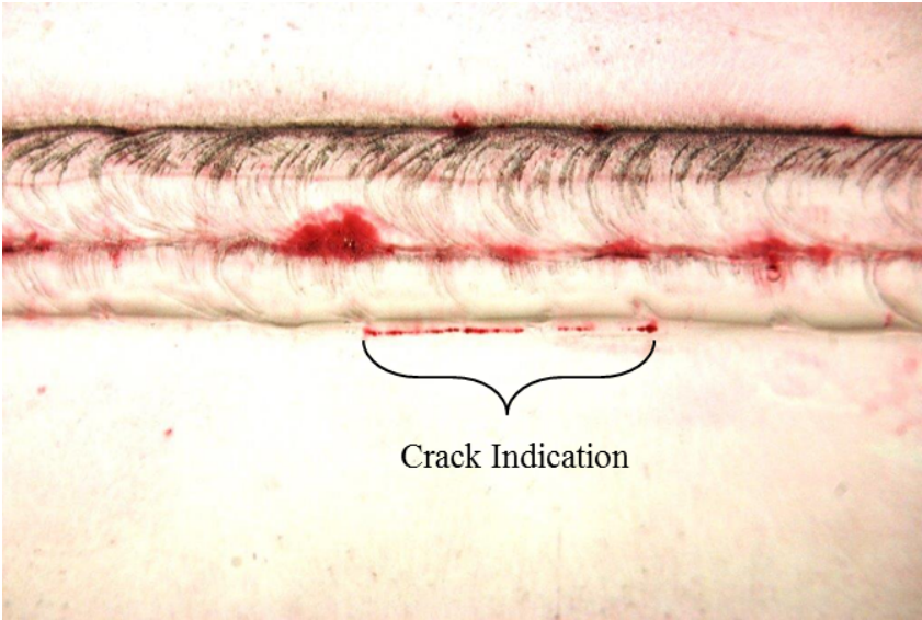
Figure 19.11 shows a crack that was identified by the liquid penetrant inspector. Figure 19.10 and 19.11 show that training is important when interpreting the results from liquid penetrant testing.
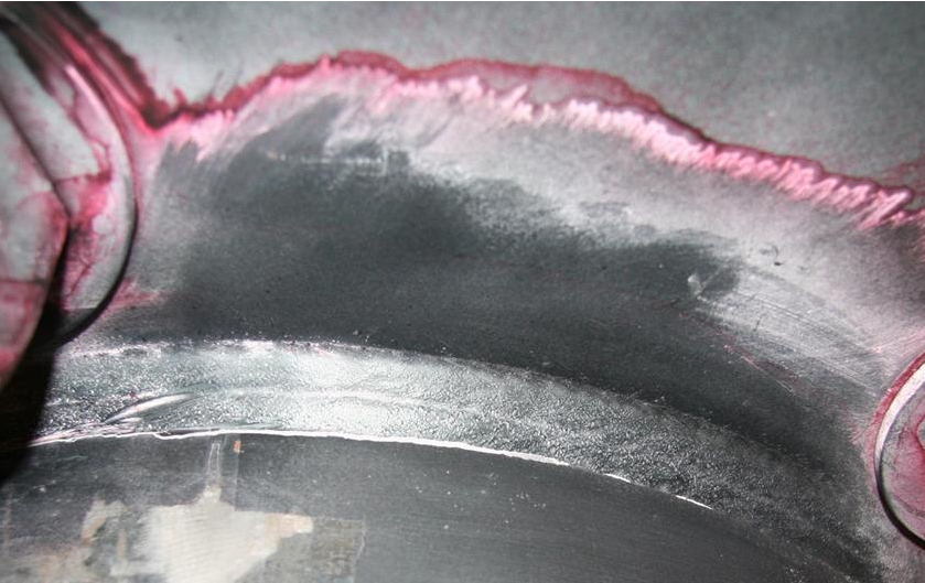
Liquid penetrant testing is used for many different parts of all different sizes. Figure 19.12 below shows possible crack indications on a part around the bolt holes in the image. If this is a cast part or a part with a rough surface, the cracks might be hard to see with the naked eye. The liquid penetrant and the developer provide the contrast that is needed to identify cracks and other discontinuities.
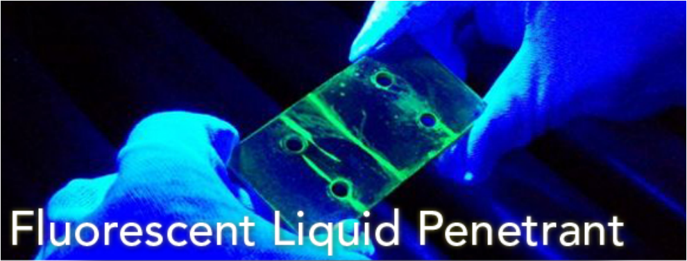
Sometimes even more contrast is required to detect defects in fabrications. Fluorescent liquid penetrant testing provides additional contrast as shown in Figure 19.13. A black light is used in a dark room to react with the fluorescent liquid penetrant to provide the bright indications for the inspector to interpret. Again, note the gloves being used to protect the inspector from the chemicals used; the liquid penetrant would easily dye the inspector’s hands and would likely be difficult to remove.
Leak Testing (LT)
Leak testing (LT) is a process that pressurizes the system, typically a piping system, tank, or other vessel, for a given period of time to detect any leaks in the system. Figure 19.17 shows hoses being attached to a piping system to test for leaks prior to the pipes being buried underground.
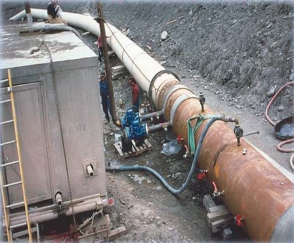
Finding leaks prior to burial makes repairs much easier because the dirt does not have to be removed, and it is also safer because the pump that is pressurizing the system has a much lower flow rate than the normal flow within the piping system at in-service conditions, meaning that a weld failure during leak testing won’t leak as much volume of liquid. Think of your garden hose that you turn off at the valve on the side of a building; the hose is still pressurized but when you open the other end of the hose only a small burst of water comes out.
Magnetic Particle (MT)
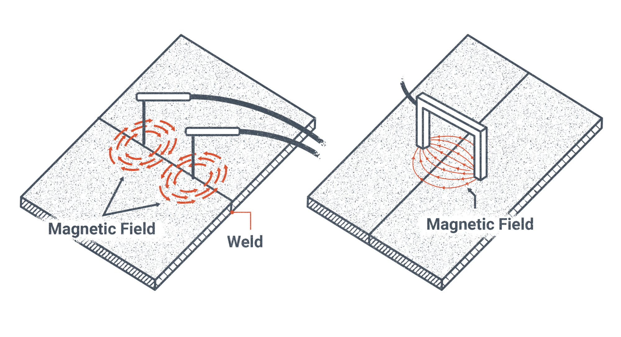
Magnetic Particle (MT) is a process that uses a magnetic field and fine magnetic particles that will orient themselves in that magnetic field to make discontinuities visible. Figure 19.15 below shows different types of prods inducing magnetic fields around a weld.
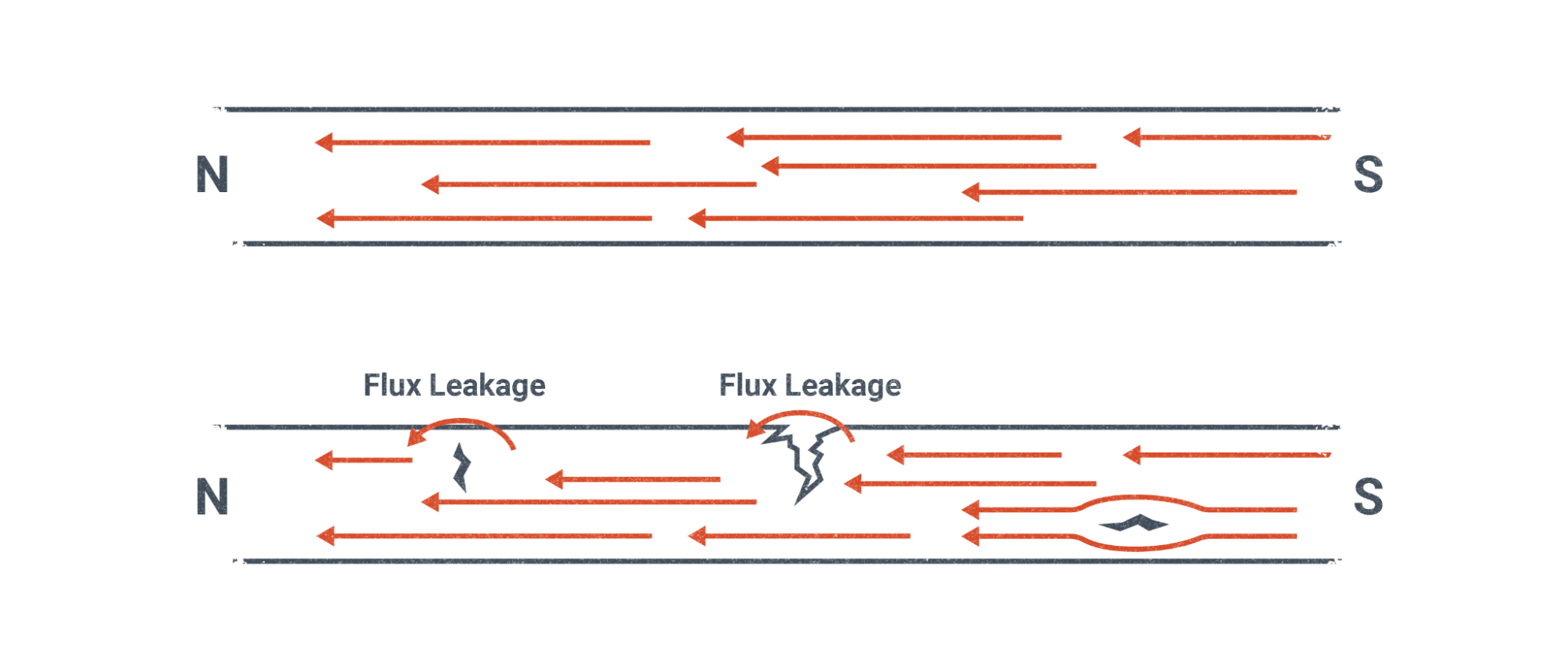
Magnetic particle testing can only be performed on magnetic materials to be effective. Because defects within magnetic materials change the direction of the magnetic field, the magnetic particles located on the surface of the weldment will move and align themselves in a particular pattern due to the shape of the discontinuity. Only discontinuities that are not parallel to the magnetic field are detectable, see the right side of Figure 19.16.
In practice the magnetic particle inspector will apply the magnetic particles from a bottle, similar to applying baby powder from a bottle. Figure 19.17 below shows the inspector actively applying the iron powder from a red bottle in their right hand while holding the yoke in their left hand. The massive fillet weld along the T-Joint that is being illuminated by the flash light in the picture is likely being inspected.
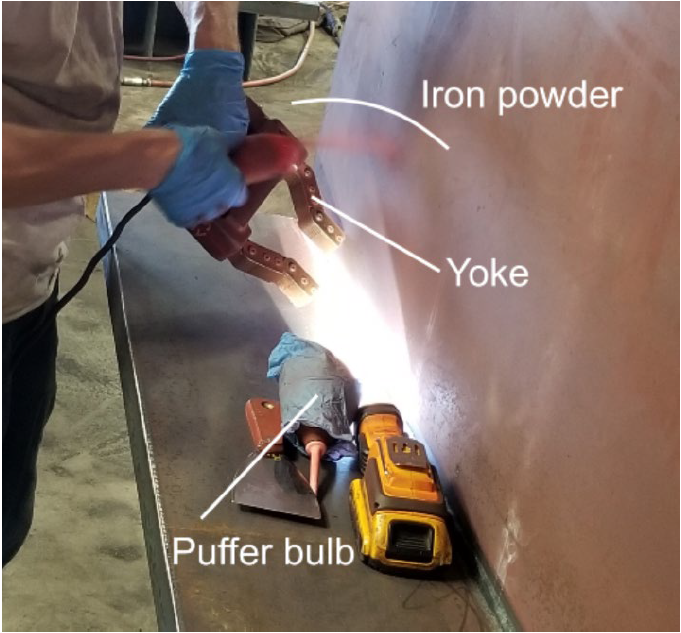
The magnetic particle inspector will take great care to gently blow the excess magnetic particles with the puffer bulb. If the inspector is too aggressive with the puffer bulb, they will blow too many magnetic particles away and possibly miss an indication of a discontinuity. If they don’t blow away enough particles, then the indication of a discontinuity will be masked.
Eddy Current Testing (ECT)
Eddy Current Testing (ECT) is a process that induces currents into the weldment being inspected. Figure 19.18 shows an electric coil with an alternating current (AC) signal applied to it. Alternating current is current that changes direction regularly. The electricity that is supplied from the wall outlets in your home or at school are 60 Hz AC, meaning the signal has 60 cycles per second with two changes in direction per cycle for 120 changes per second.
You may have heard the term electromagnetism before. This term refers to the fact that electricity and magnetism are forces that act together. To be super technical about it, electricity and magnetism are two effects that result from an electric charge; magnetism results from a moving charge while electricity can occur with both a moving and non moving charge. For moving charges think of electricity in a wire and for non-moving charges think static electricity or a disconnected charged battery.
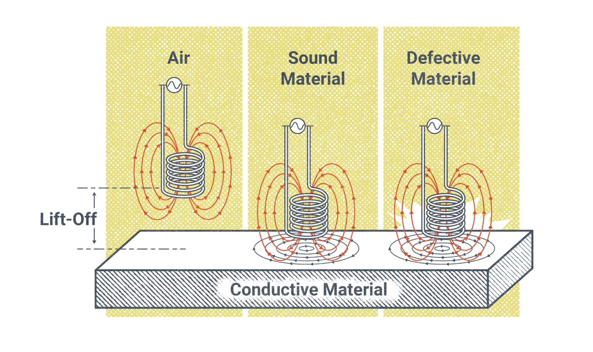
Figure 19.18 shows the magnetic field from the coil when it is too far away from the conductive material to induce a magnetic field. In the middle of Figure 19.18 the coil is close enough to induce a magnetic field with a uniform field because there are no discontinuities, while the position on the right has a disturbed magnetic field.
Similar to the magnetic particle testing in the previous section, eddy current testing can only detect discontinuities that are not parallel to the lines of the magnetic field. Discontinuities that are parallel, or mostly parallel to the lines of the magnetic field do not produce a strong enough signal to detect. Figure 19.19 shows the disturbed lines of magnetic force due to the presence of the discontinuities. If the discontinuities did not exist in Figure 19.19, then the lines of magnetic force would be concentric circles. Notice in the Figure that the crack that is perpendicular to the magnetic lines interrupts the magnetic lines by pushing them further apart as they go around the crack, and the crack parallel to the magnetic lines does not affect the magnetic lines enough to notice.
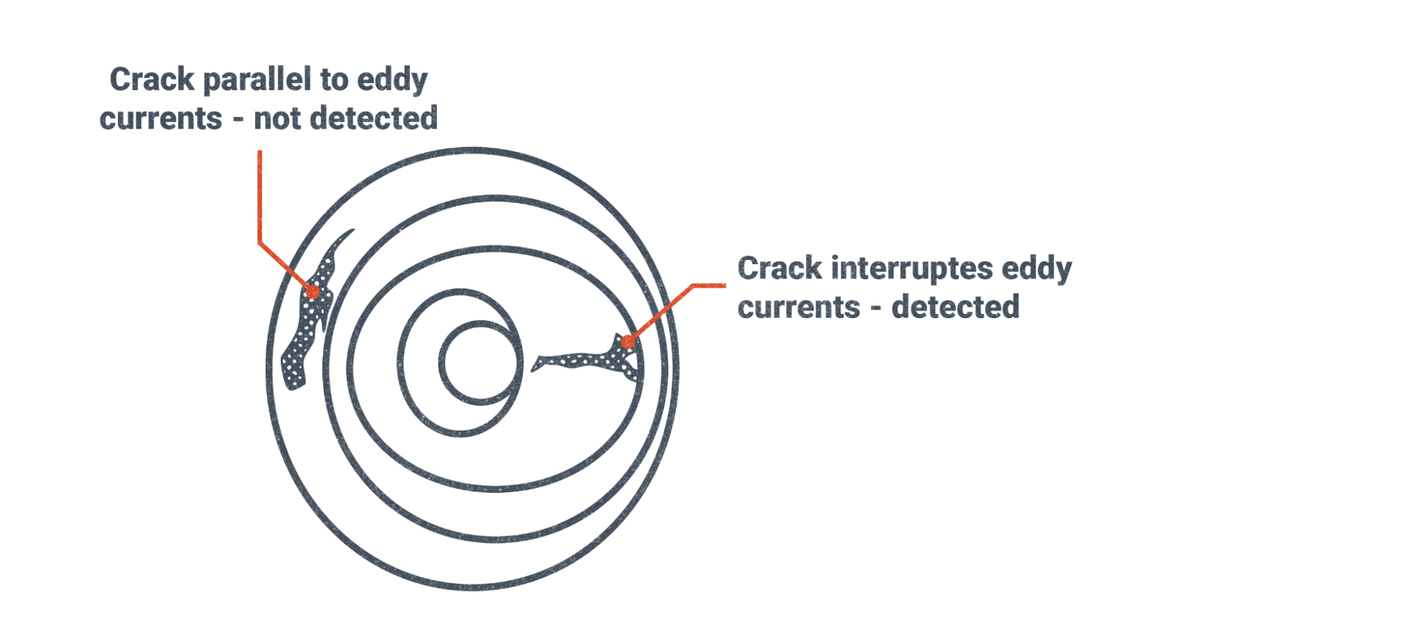
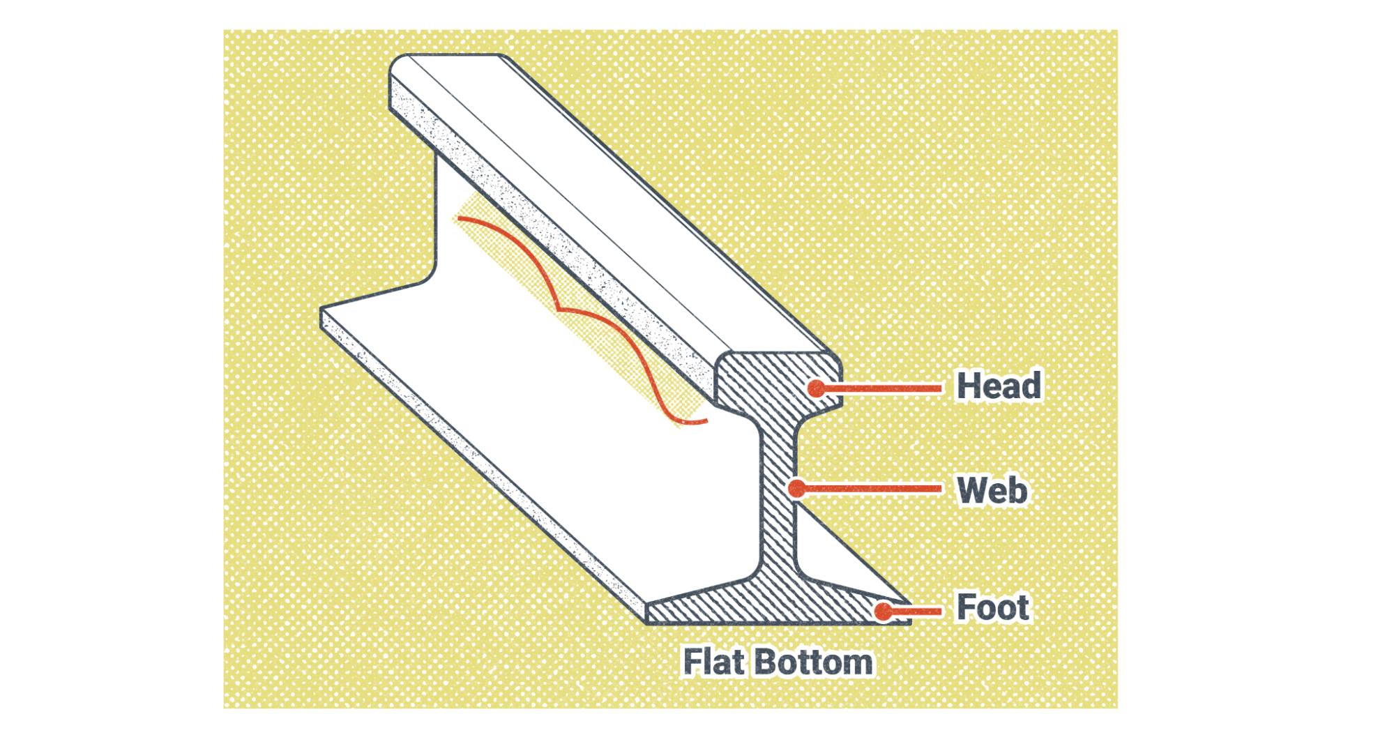
Figure 19.20 illustrates a crack that exists on a small piece of a railroad rail. Figure 19.21 is a composite of multiple pictures that show the indications of the cracks on the screen and pictures of the rail and close up pictures of the cracks that are being displayed on the screen.
Before we look at Figure 19.21 in detail let’s explain why there are two screens shown, one labeled “Real part of Impedance” and the other “Imaginary part of Impedance.” Mathematically, electromagnetism has real and imaginary values when measuring it. We are all familiar with real numbers such as whole numbers, decimals and fractions. We use them in welding settings on our machines such as 95 Amps, or 24 Volts. For engineers and technicians working with electromagnetism it is easier to describe electromagnetism with a complex number, meaning a number with a real and imaginary part than to describe it using amperage, voltage, capacitance, and inductance.
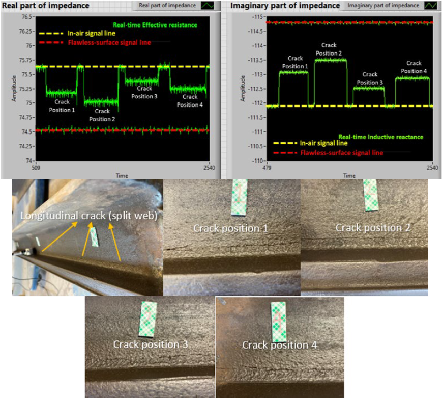
An in depth discussion of complex numbers is beyond the scope of this chapter, but it was worth mentioning in case you were curious about the “Imaginary part of impedance.” capacitance is the resistance to a change in voltage while inductance is the resistance to a change in current. Inductance is a setting on your welding machine to control spatter when welding GMAW in the short circuit transfer mode. By increasing the inductance you reduce the amount of spatter that occurs when the wire short circuits with the workpiece. Turning up the inductance too much will cause stubbing where the wire hits the workpiece and pushes your welding gun away. Inductance will be discussed more in the GMAW and/or welding machine chapter.
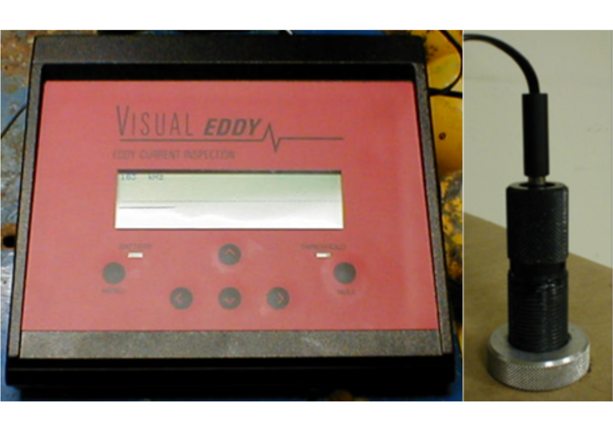
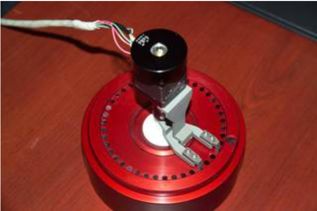
Figure 19.22 shows another example of a digital readout of an eddy current test with a flaw being indicated on the screen (Left) and an eddy current probe (Right). Below that Figure 19.23 shows another type of eddy current probe that you may see in the field.
Radiographic Testing (RT)
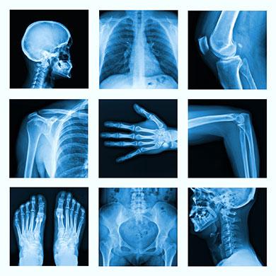
Radiographic Testing (RT) uses X-rays to penetrate weldments so we can see into what is normally not visible to the naked eye. If you have ever had an x-ray for medical reason or even had a friend showing off an x-ray of a broken bone you are familiar with some of the images in Figure 19.24. If you haven’t seen an x-ray of the human body, Figure 19.24 shows the powerful imagery it can provide.
An X-Ray works by positioning your weldment between the X-Ray source and a piece of film or digital sensor.
As times change so does Radiography. With the market for analog film being mostly medical, once the medical field goes to all digital radiography the cost of film would skyrocket and welding inspectors will switch to digital radiography also. Figure 19.25 shows film under the weldment, but in digital radiography a digital sensor would replace the film.
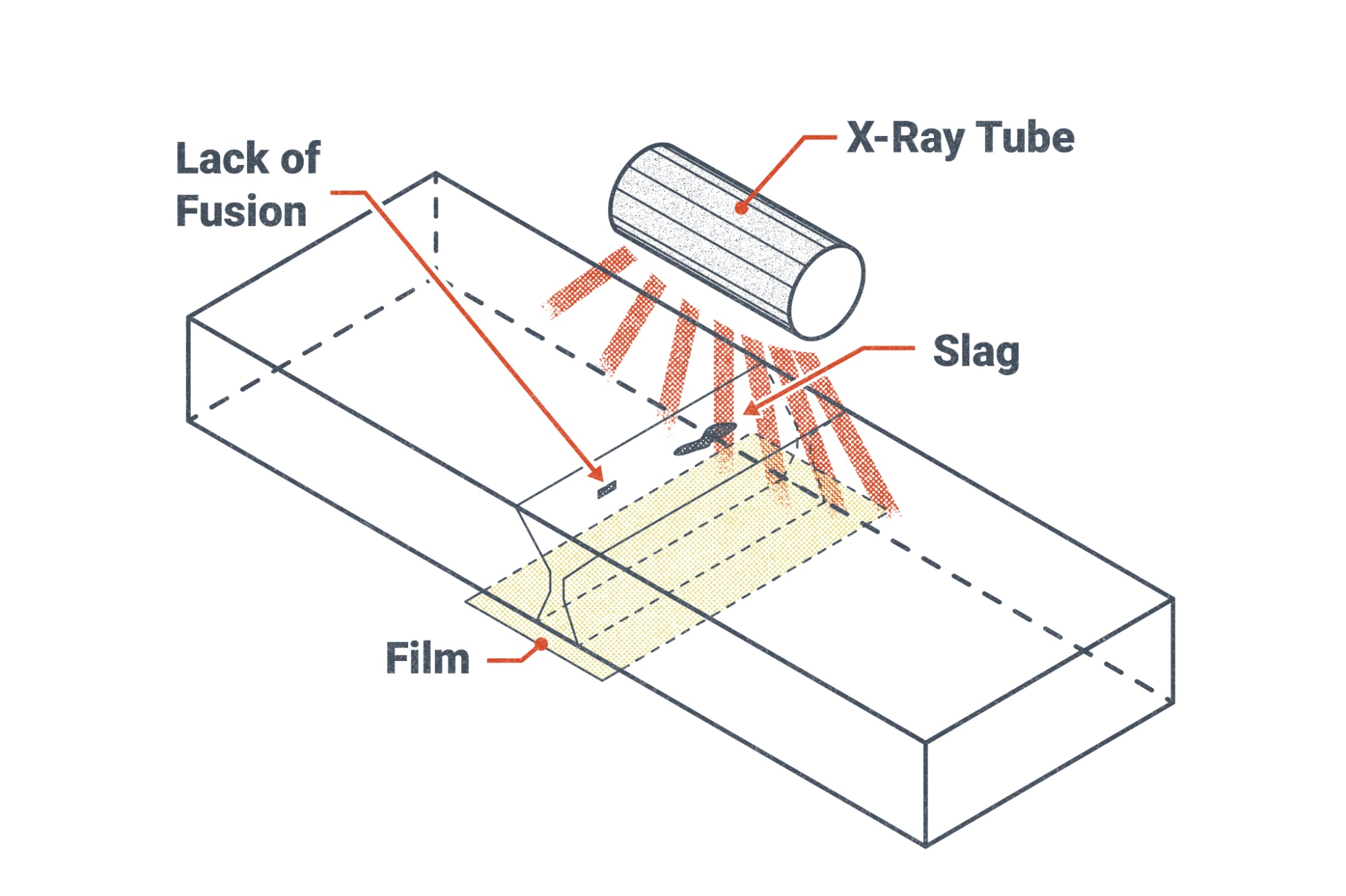
An actual image of a similar X-Ray tube used in Figure 19.25 is found in Figure 19.26 below.
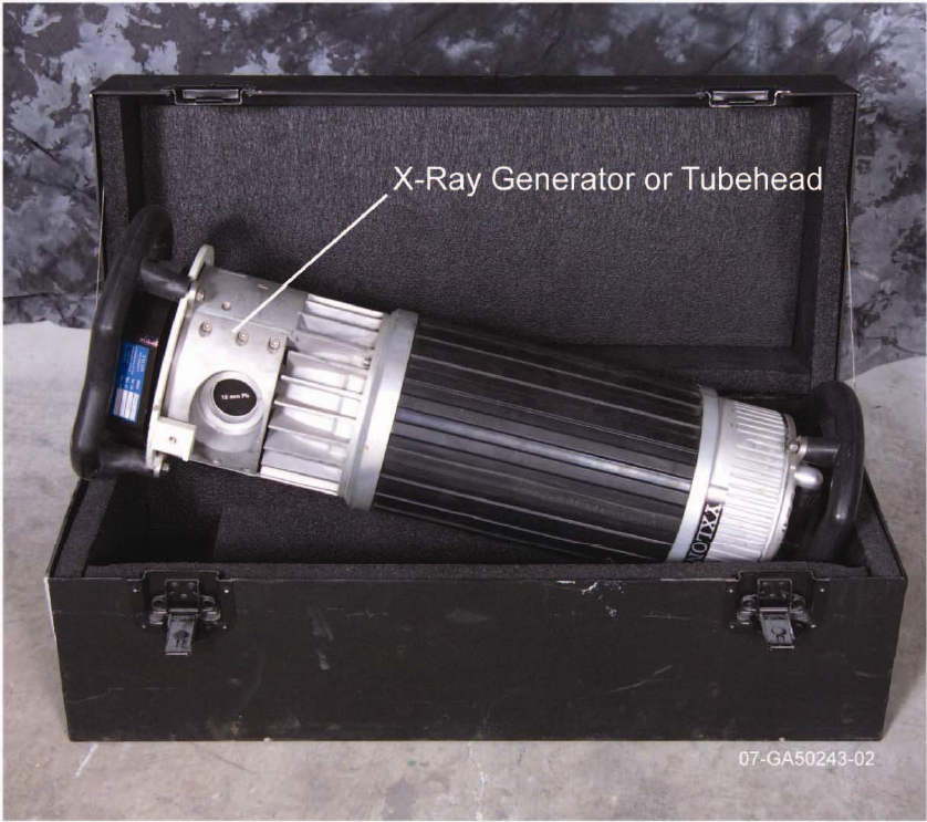
For safety the X-Ray generator has a lead plug to protect against the X-Rays when not in use. These generators should only be handled by qualified personnel or personnel being trained under the supervision of a qualified inspector because they can generate a lethal x-ray dose. Any time radiation is involved as an occupational hazard, the term ALARA is used which stands for As Low As Reasonably Achievable. ALARA is achievable through decreased exposure time and increased distance to/from the radiation source.
In practice this means that only those personnel who have to be near the X-Ray generator will be near it for as short a time as possible. Otherwise personnel will make as much distance between themselves and the source of radiation as possible. This is why when you get a medical x-ray the technician leaves the room; you getting a handful of X-Rays in your lifetime is much much different from the technician getting exposed to a dozen X-rays per working day.
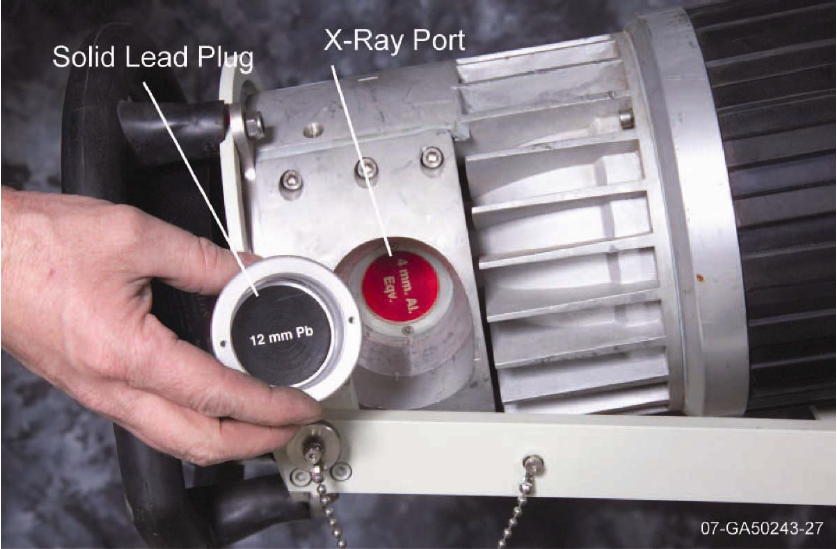
Figure 19.27 shows the plug removed with the X-Ray source behind it. Figure 19.28 shows a radiographic inspection of a weldment. In this Figure you can see the weldment is in between the X-Ray source and a plate of film which is underneath the weld. As part of the inspection process Image Quality Indicators (IQIs) are used to ensure that the radiograph can detect a minimum required detail. If the letters of the IQI are not readable, the radiographic inspection is not acceptable and must be redone. These IQI’s can be seen in Figure 19.29.
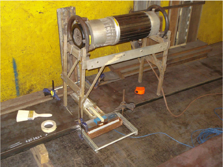
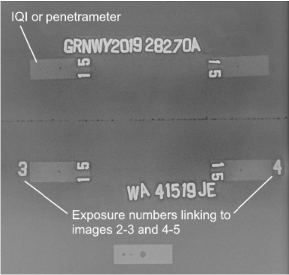
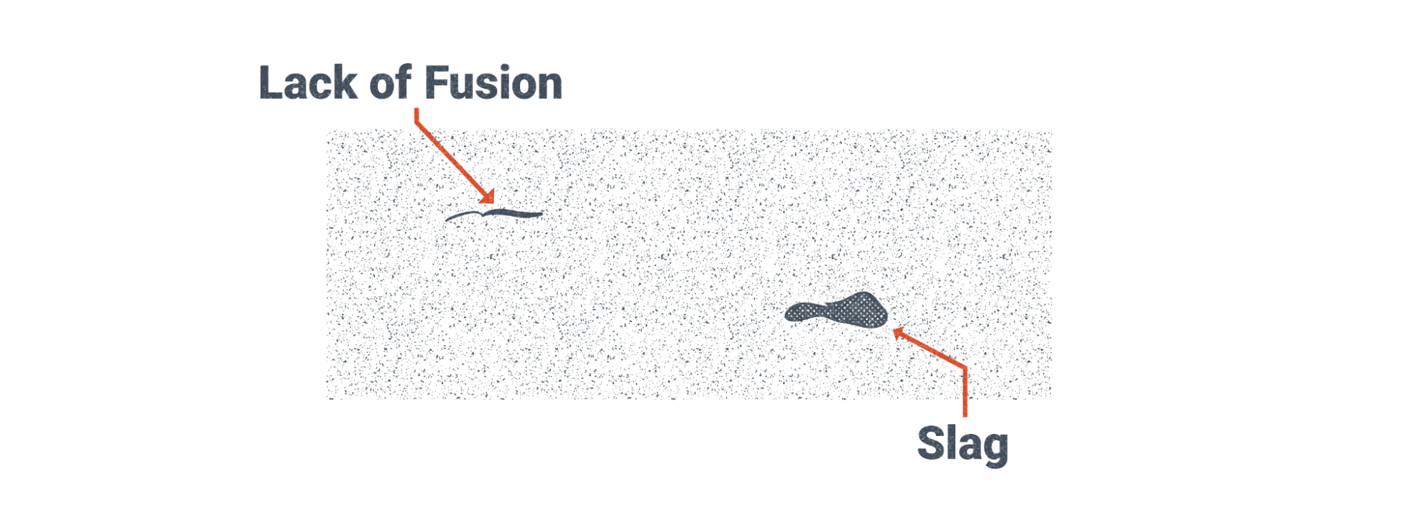
Figure 19.30 and Figure 19.31 show illustrations of what welding discontinuities would look like. Trained welding inspectors know what to look for when they are inspecting weldments.
Ultrasonic Testing (UT)
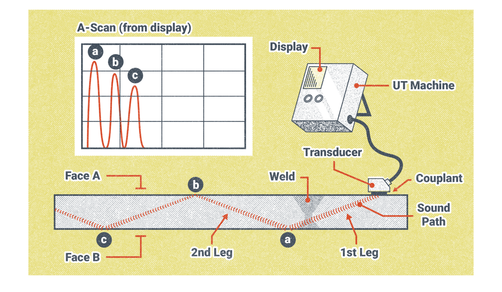
Ultrasonic Testing (UT) is a technology that was adapted from the medical field similarly to Radiographic Testing which was discussed in the previous section. Instead of using radiation, such as X-Rays, ultrasonic testing uses sound waves. The transducer shown in Figure 19.32 and 19.33 both sends and receives the sound waves.
There are many different types of UT, for the discussion in this chapter we will stick to the UT depicted in Figure 19.32. Other forms of UT are immersed UT where the specimen being inspected is submerged in a pool of water and the transducer is located away from the surface of the weldment. There is also UT where there is an air gap between the transducer and the weldment being inspected. These two forms of UT are beyond the scope of this chapter and will not be discussed.
In Figure 19.32 there is a couplant which is usually in the form of a gel that is applied to the surface of the weldment. This couplant ensures that the transducer is “coupled” to the weldment in a way that allows sound waves to pass through the transducer and into the weldment. If an air gap existed between the transducer and the weldment due to a non-level surface, the air gap would interfere with the results of the UT inspection.
The inspector then slides the transducer into position. This sliding action requires a smooth surface generally free of spatter. Remove spatter prior to UT if requested or required.
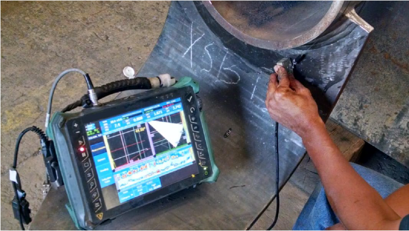
As we saw in the first Chapter image, and in Figure 19.37, the inspector holds the transducer with their fingers and moves it around while watching the display. If you have watched a tv show, commercial, or been in a doctors office when an ultrasound was being performed you are familiar with the technician moving the transducer around on the patient’s body as they watch the image on the screen. You may even remember the gel couplant that was applied to the skin.
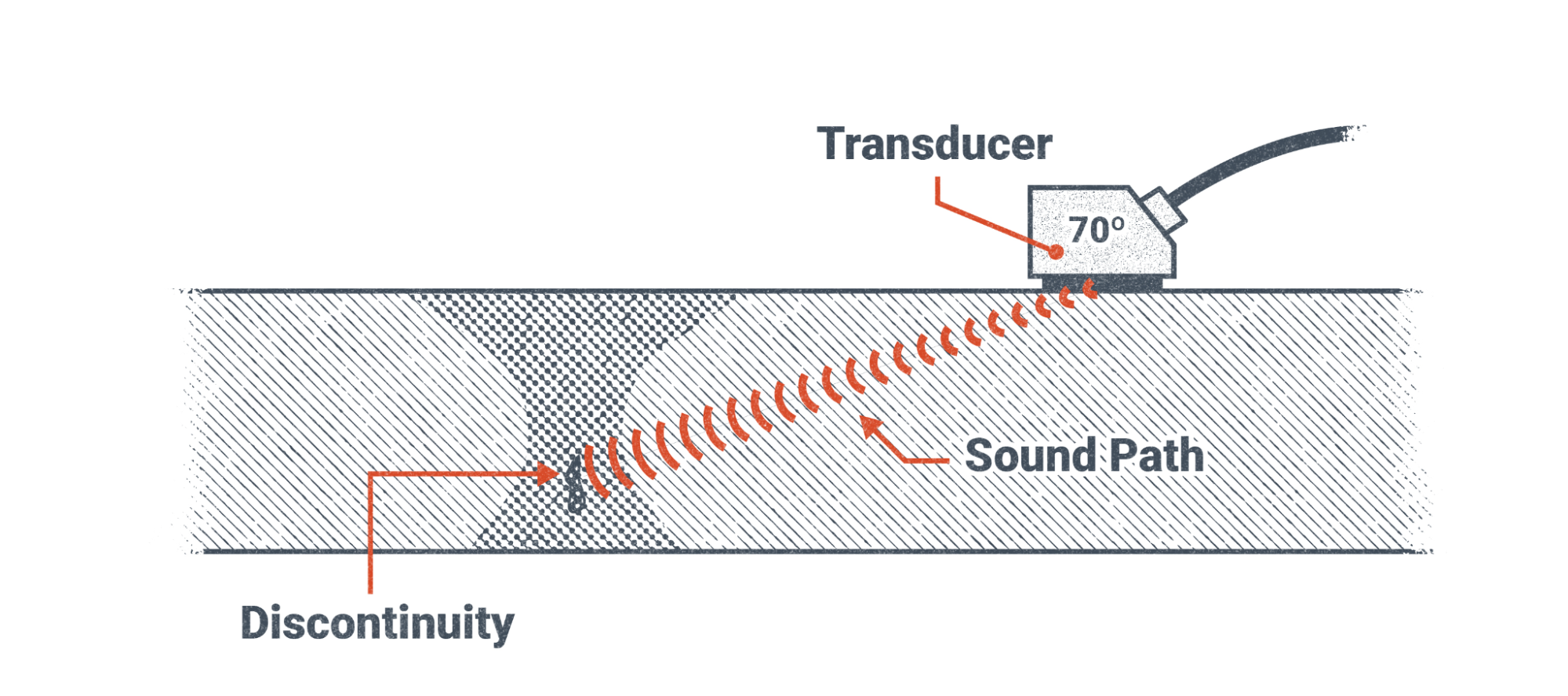
The distance between the weldment and the transducer allows for the depth of the discontinuity to be calculated. In reality the time it takes for the ultrasonic wave to return determines the distance, and the angle of the transducer allows for the depth to be calculated from the distance the sound traveled. The spikes seen in Figure 19.32 are interpreted by the trained technician. Some spikes are expected, such as the initial bang which represents sound bouncing back from the surface of the material directly next to the transducer, spikes from surface reflectivity as shown in Figure 19.32, and discontinuities.
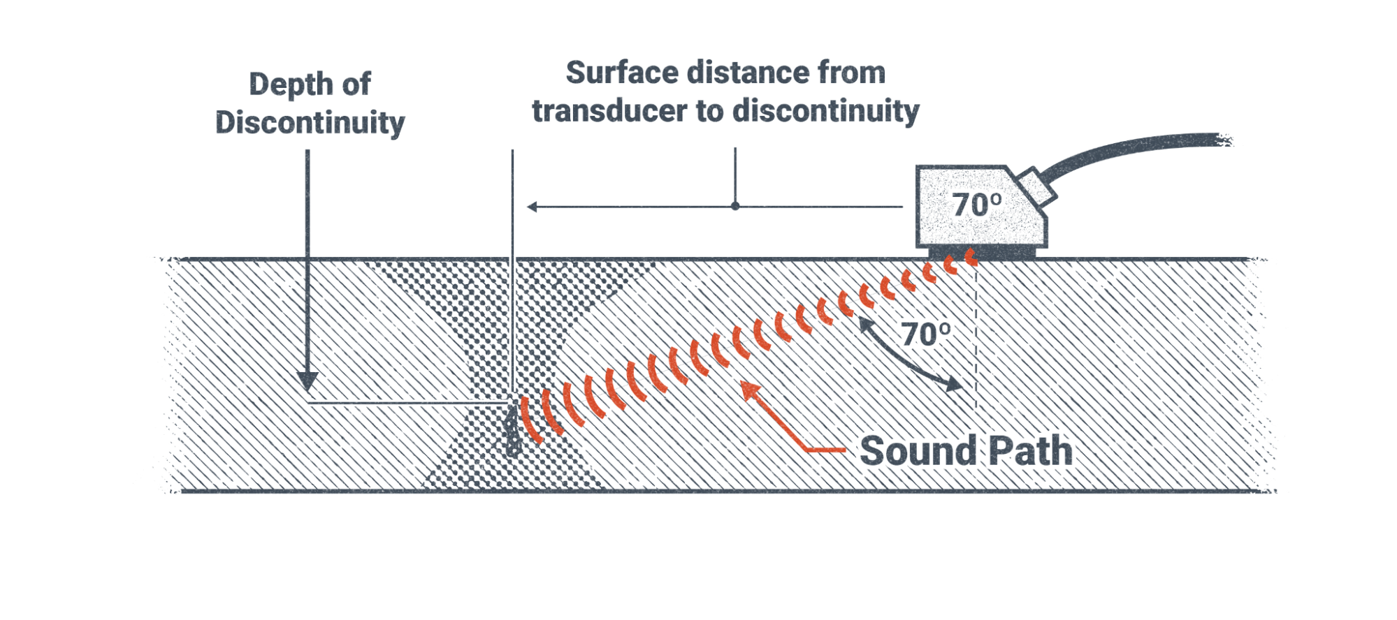
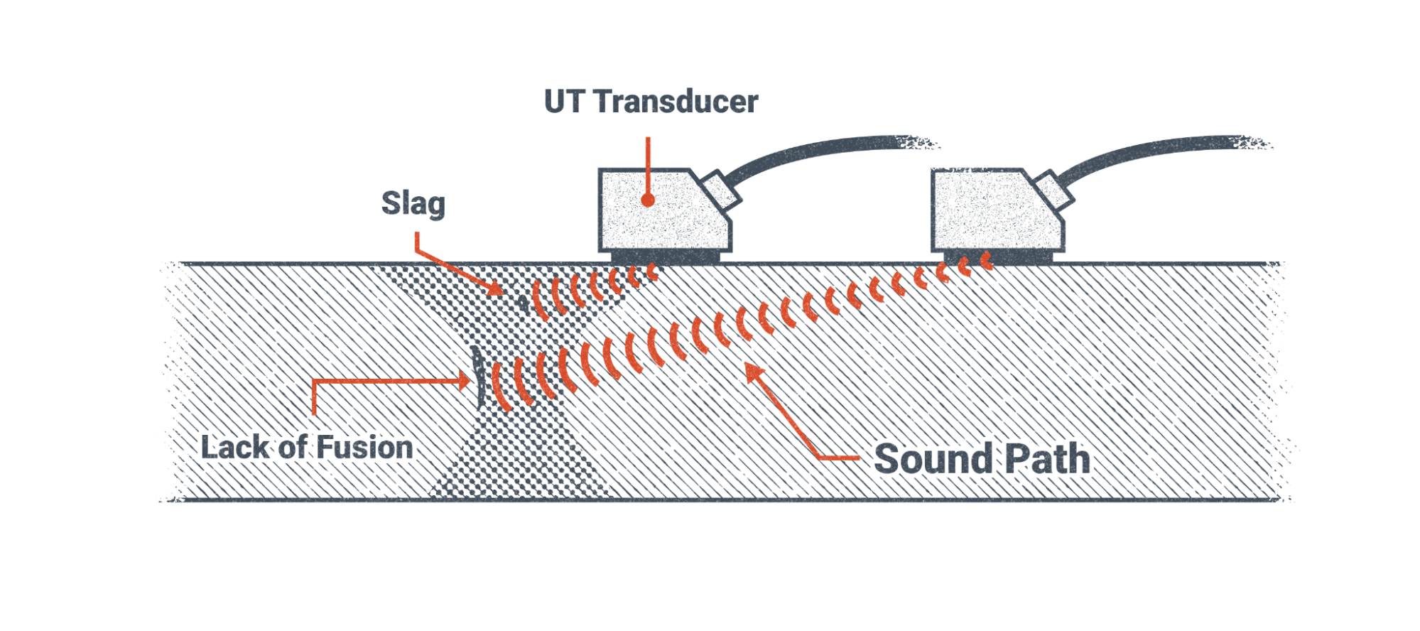
Figure 19.35 below shows two transducers in the figure. This image is showing how the position of the transducer will detect different discontinuities at different depths into the weldment based upon the transducer’s position. The closer the transducer is to the discontinuity, the shallower it is.
An improvement upon the single transducer previously discussed is Phased Array UT (PAUT). With a phased array, multiple transducers within a single element transmit ultrasonic sound waves into the weldment being examined. This allows for a more complete picture to be formed on the screen. See the images in Figure 19.37 and Figure 19.38.
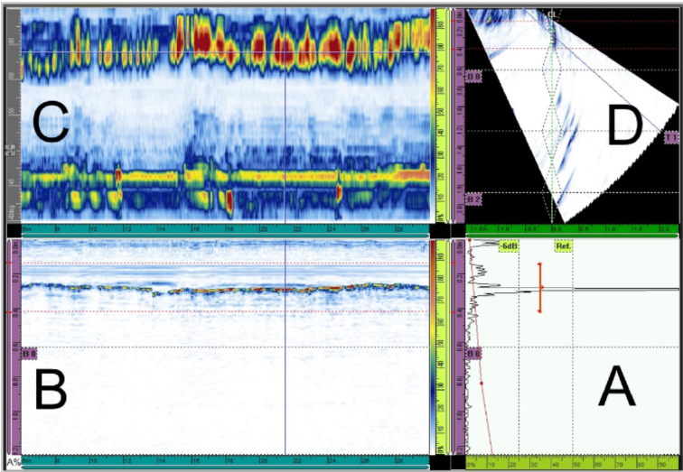
The image shown in section D of Figure 19.38 depicts discontinuities encountered in a weldment being inspected. Again, these images are interpreted by a trained inspector and not by welders. That being said, it is still important for the welder to be familiar with the inspection techniques used so the proper preparation of the weldment can be performed prior to the inspection.
Attributions
- Figure 19.1: Overlap in a fillet weld by United States Department of Transportation, Federal Highway Administration in the Public Domain; United States government work
- Figure 19.2: Example of porosity by United States Department of Transportation, Federal Highway Administration in the Public Domain; United States government work
- Figure 19.3: Example of slag trapped in a CJP weld by United States Department of Transportation, Federal Highway Administration in the Public Domain; United States government work
- Figure 19.4: Metal Weld Cracks by Nicholas Malara, for WA Open ProfTech, © SBCTC, CC BY 4.0
- Figure 19.5: Example of crack in underfilled weld crater by United States Department of Transportation, Federal Highway Administration in the Public Domain; United States government work
- Figure 19.6: Example of weld spatter by United States Department of Transportation, Federal Highway Administration in the Public Domain; United States government work
- Figure 19.7: Examples of Arc Strikes by United States Department of Transportation, Federal Highway Administration in the Public Domain; United States government work
- Figure 19.8: Applying Dye Penetrant to Surface by United States Department of Transportation, Federal Highway Administration in the Public Domain; United States government work
- Figure 19.9: Cleaning Surface to Remove Dye by United States Department of Transportation, Federal Highway Administration in the Public Domain; United States government work
- Figure 19.10: Applying Developer to Provide Contrast with Dye Emerging from a Crack by United States Department of Transportation, Federal Highway Administration in the Public Domain; United States government work
- Figure 19.11: Crack Indication Formed by Dye Emerging from Crack by United States Department of Transportation, Federal Highway Administration in the Public Domain; United States government work
- Figure 19.12: Peening evidence on Specimen 1U3 by United States Department of Transportation, Federal Highway Administration in the Public Domain; United States government work
- Figure 19.13: Part Inspection/Evaluation by U.S. Department of Energy, Office of Energy, Efficiency and Renewable Energy, National Renewable Energy Laboratory in the Public Domain; United States government work
- Figure 19.14: Test Pressure by U.S. Department of Transportation in the Public Domain; United States government work
- Figure 19.15: Magnetic Testing Prods (L) Yoke (R) by Nicholas Malara, for WA Open ProfTech, © SBCTC, CC BY 4.0
- Figure 19.16: Magnetic Testing Particle Accumulation by Nicholas Malara, for WA Open ProfTech, © SBCTC, CC BY 4.0
- Figure 19.17: Magnetic Testing by United States Department of Transportation, Federal Highway Administration in the Public Domain; United States government work
- Figure 19.18: Eddy Current Testing by Nicholas Malara, for WA Open ProfTech, © SBCTC, CC BY 4.0
- Figure 19.19: Eddy Currents and Flows by Nicholas Malara, for WA Open ProfTech, © SBCTC, CC BY 4.0
- Figure 19.20: Crack Location in a Rail by Nicholas Malara, for WA Open ProfTech, © SBCTC, CC BY 4.0
- Figure 19.21: Magnetic Testing by United States Department of Transportation, Federal Highway Administration in the Public Domain; United States government work
- Figure 19.22: Left: Eddy Current Equipment used in the Project. This is one of several systems that are commercially available for eddy current inspection of thread regions. The authors, the RSPA and the DOT do not endorse any specific system manufacturer. Right: Closeup of an Eddy Current Probe Threaded onto the Calibration Block by Research and Special Programs Administration and the Department of Transportation in the Public Domain; United States government work
- Figure 19.23: An eddy current probe fixture is used to evaluate a thruster center body diffuser nozzle. by NASA White Sands Test Facility in the Public Domain; United States government work
- Figure 19.24: Radiation in Healthcare: X-Rays by U.S. Department of Health and Human Seervices, Centers for Disease Control and Prevention in the Public Domain; United States government work
- Figure 19.25: Radiographic Testing by Nicholas Malara, for WA Open ProfTech, © SBCTC, CC BY 4.0
- Figure 19.26: X-ray generator shipping box by Idaho National Laboratory in the Public Domain; United States government work
- Figure 19.27: Installing solid plug by Idaho National Laboratory in the Public Domain; United States government work
- Figure 19.28: Radiography in a bridge shop by U.S. Department of Transportation, Federal Highway Administration in the Public Domain; United States government work
- Figure 19.29: Radiography in a bridge shop by U.S. Department of Transportation, Federal Highway Administration in the Public Domain; United States government work
- Figure 19.30: Radiographic Testing by Nicholas Malara, for WA Open ProfTech, © SBCTC, CC BY 4.0
- Figure 19.31: Illustration of notional radiographic inspection of metal weld cracks by NASA in the Public Domain; United States government work
- Figure 19.32: Ultrasonic Testing Butt Joint Schematic by Nicholas Malara, for WA Open ProfTech, © SBCTC, CC BY 4.0
- Figure 19.33: Ultrasonic Testing with a 70° Transducer by Nicholas Malara, for WA Open ProfTech, © SBCTC, CC BY 4.0
- Figure 19.34: Ultrasonic Testing Discontinuity Distance by Nicholas Malara, for WA Open ProfTech, © SBCTC, CC BY 4.0
- Figure 19.35: Ultrasonic Testing by Nicholas Malara, for WA Open ProfTech, © SBCTC, CC BY 4.0
- Figure 19.36: Phased Array Ultrasonic Testing by Nicholas Malara, for WA Open ProfTech, © SBCTC, CC BY 4.0
- Figure 19.37: Use of PAUT for an unusual CJP bridge weld by U.S. Department of Transportation, Federal Highway Administration in the Public Domain; United States government work
- Figure 19.38: PAUT examination output by U.S. Department of Transportation, Federal Highway Administration in the Public Domain; United States government work
The use of carbon rods make a sizeable impact in welding’s history in 1800 with Sir Humphrey Davy who created an arc between to carbon rods and again 1881 with Nikolay Benardos & Stanisław Olszewski who used that discovery to create Carbon Arc Welding (CAW). The use of carbon rods have been the kick off of welding. But they were late in the game when it came to their use as a cutting process. Air carbon arc cutting originated in the 1940’s. The process was used to cut away rivets in the overhead and vertical positions in hopes that gravity would then assist with the molten material to drop from place. This was a time consuming and erratic process. Not only was the molten dross or sparks unpredictable, but the rivets would not always fall away as planned. Sometimes they would reweld themselves back in place. (The History of Welding, 2020)
In 1948 a local Washingtonian named Myron Stepath added compressed air to the carbon arc process (Arcair, 2010). The streams of high-pressurized compressed air act as a blower to push the molten dross, sparks, and material to be removed, away from the cutting area. This not only was more efficient but allowed the workers to increase their speed and expand the process to flat positions as well. The process then became known as air arc cutting (aac). AAC required two workers, one to operate the carbon arc, and the other to operate the compressed air needed to blow away the molten metal.
In 1956 the process was then refined even further with the development of the electrode holder we use today (Arcair, n.d.). This development brought the compressed air stream into an easy to use handheld electrode holder, eliminating the need for two people for the job.
Basics of the process
Carbon Arc is an electric arc process where the heat generated from the arc of a carbon electrode melts the base metal it comes in contact with. Carbon arc welding is one of the oldest versions of welding, and in its day was called atomic hydrogen carbon arc welding or AHW for short (“Atomic Hydrogen Welding,” 2023). However, CAW aka AHW has become largely obsolete. The cutting technique, Carbon Arc Cutting (CAC), which uses carbon electrodes to cut and gouge parent material is still very popular in fabrication, welding and thermal cutting industries today.
Carbon arc cutting is used to cut away unwanted material by means of a carbon coated consumable rod or electrode held in the jaws of a holder that looks very similar to the holder used in shielded metal arc welding (SMAW). There are a few key differences with the equipment and the process. The biggest is, that unlike welding where we are adding metal, CAC-A removes metal, welds, cracks and helps bevel grooves in fit up operations.
The bottom or lower jaw of the holder used in carbon arc cutting has a head that rotates to insure accuracy and is outfitted with several holes in the head for the compressed air to pass through. Recall that compressed air is needed to blow away molten metal from the cutting area. There is an air valve on the handle to turn the air on or off to the head. When positioned correctly and with the right air pressure, the compressed air then blasts the molten metal away from the site directly under the electrode.
There is no shielding gas used or needed, but as the carbon rod is consumed it produces both carbon monoxide and carbon dioxide gas which is also blasted away by the air stream. Because this process uses carbon electrodes, carbon deposits are left behind on the surface metal. It is important to take care in cleaning the surface afterwards with a grinder to avoid brittleness and cracking should the area need to be rewelded, or back-welded.
Carbon arc cutting does not require that the carbon electrode react to the base metal. Which allows for more versatility than oxy-acetylene cutting (OAC), which is only effective on metals that can be oxidized. Stainless steel, carbon steel, titanium, copper alloys, nickel alloys, and aluminum alloys are just a few of the materials an individual may use CAC-A process with.
Carbon arc cutting can be used in all positions. The process can be done fully manual or semi-automatic when connected to a carriage or machine that controls the speed and movements. The cutting process requires a constant current (CC) power source capable of an operating voltage of at least 28 volts or higher. Carbon arc cutting can be operated with AC or DCEP, however DCEN should be avoided, as the arc is too unstable.
Uses of CAC-A in industry today
- Boilermakers
- Railway
- Steel mills
- Steel Fabrication
- Construction
- Chemical and Petroleum industry
- Casting finishing
- Mining industry
- Foundries
- Lumber industry
- Military

Overview
When was the last time you were in a large steel-framed building, like a skyscraper or crossed over a steel bridge? When did you last pass by a crane or excavator on a construction site or see a large steel ship sailing in the ocean? These things are very different, but they share one thing in common: they were all likely welded using the flux-cored arc welding (FCAW) process.
FCAW is a widely employed process used in a variety of heavy industries, including the steel frames of buildings and bridges, shipbuilding, and heavy equipment manufacturing. This chapter will introduce readers to the development of the process and its equipment, industrial applications, and fundamental techniques.
Objectives
After completing this chapter, students will be able to:
- List the uses of FCAW-G & FCAW-S in industry
- Describe the advantages and limitations of FCAW
- Identify equipment associated with FCAW
- Classify electrodes and shielding gasses used for FCAW
- Explain the fundamentals of FCAW welding techniques
Key Terms
- Automation
- Constant voltage (CV)
- Deoxidizing and denitrifying
- Electrical stickout
- Electrode
- FCAW-G
- FCAW-S
- Ferrous
- Flux
- Mechanization
- Non-ferrous
- Semiautomatic
- Shielding gas
- Volt-amp curve
Attributions
- Chapter opening image: High-rise buildings of Manhattan during sunset by Ben o'bro is released under CC0
Components
FCAW is a semiautomatic process, which has an impact on the complexity of the equipment involved. With welding processes that are considered manual, the equipment is usually solid-state; that is, there are no moving parts. In contrast, FCAW always involves a mechanical wire-feeding unit that feeds the electrode into the weld pool with the touch of a button (or, more typically, a trigger), which sharply increases productivity and reduces the required operator skill. The trade-off is a higher initial investment in the equipment and a more in-depth troubleshooting process to solve welding issues.
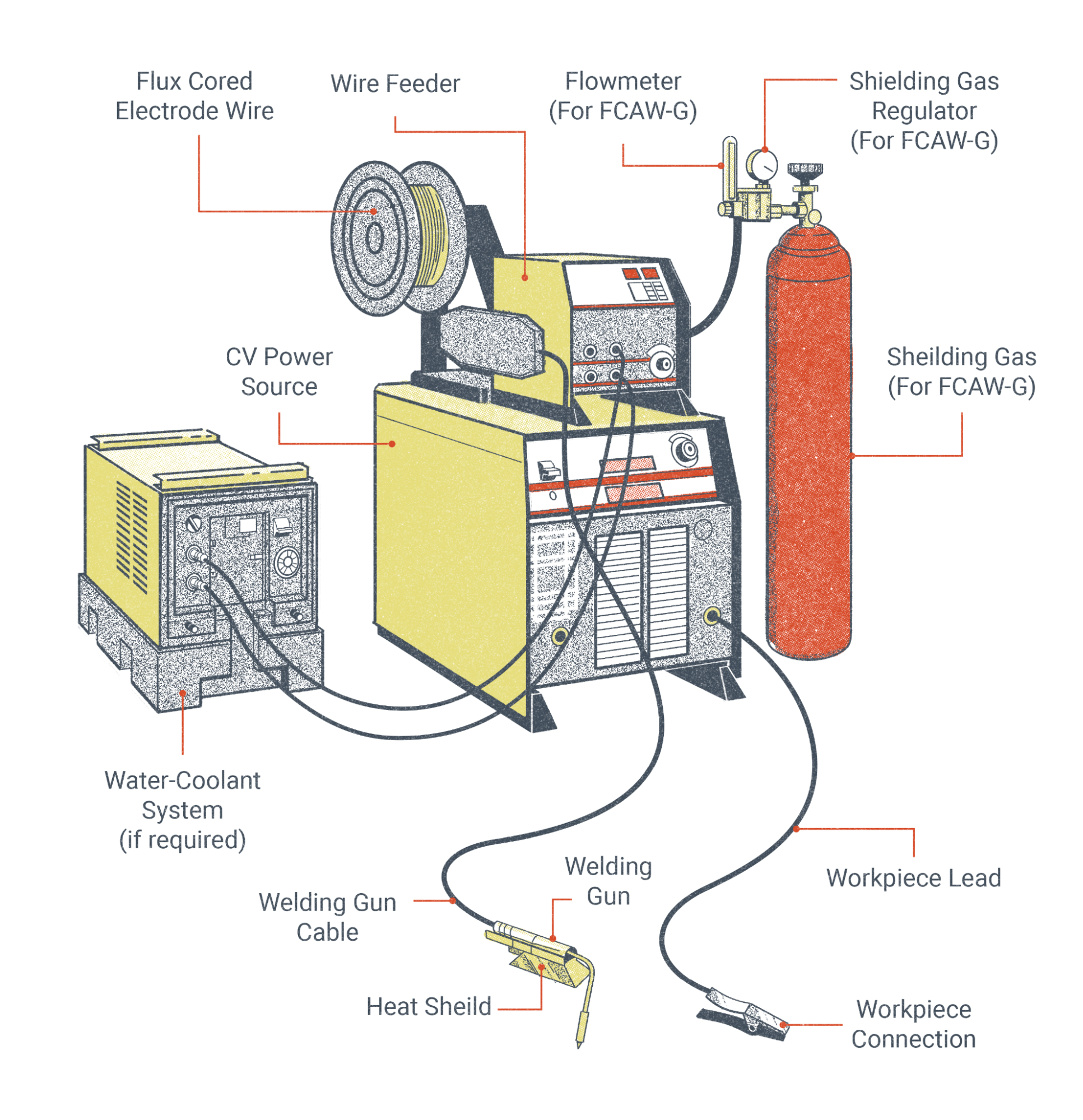
The major components necessary for the FCAW process include:
- Welding power source
- Welding gun and cable
- Workpiece lead and clamp (ground cable/clamp)
- Wire feeder
- External shielding gas (needed for FCAW-G but not FCAW-S)
- Flux-cored wire electrode
The rest of this section explores these components in depth, with the exception of electrodes and shielding gas, which have their own devoted sections.
Welding Power Source
Welding power sources for FCAW may come in the form of transformer rectifiers, though inverter machines—which are capable of multiple welding processes—are becoming the mainstay of the modern welding industry. These welding machines may range in size from compact light-duty units, with the wire feeder and power source integrated into one unit, to large engine-driven welder generators. In industrial applications, an FCAW power source will typically be heavy duty, capable of operating at 100% duty cycle at currents of up to 400 amps or more.
Power sources for FCAW must be capable of producing constant voltage (CV) output, sometimes referred to as constant potential (CP). CV machines produce a volt-amp curve that is nearly flat as opposed to constant current (CC), which produces a steeply sloped volt-amp curve. What this means for you, the welder, is that the welding arc will have small voltage changes and drastic amperage changes depending on your electrode extension. Also, unlike CC, CV processes do not give the welder direct control over welding amperage; instead, the welding voltage is controlled directly at the power source while the amperage is dependent on the wire feed speed and electrode diameter. These three things—voltage, wire feed speed, and electrode diameter—must all be selected in conjunction with each other for a smooth welding operation. It should be noted that many modern welding machines are capable of producing either a CV or CC output, so you won’t necessarily be using or avoiding specific machines. Note that alternating current (AC) should not be used with wire-fed processes like FCAW.
When selecting the polarity at the power source, it is important to check the recommended welding parameters for whatever electrode you will be using. While some of the most commonly used FCAW electrodes for steel operate on direct current electrode positive (DCEP), many are designed to run on direct current electrode negative (DCEN).
Welding Gun and Cable
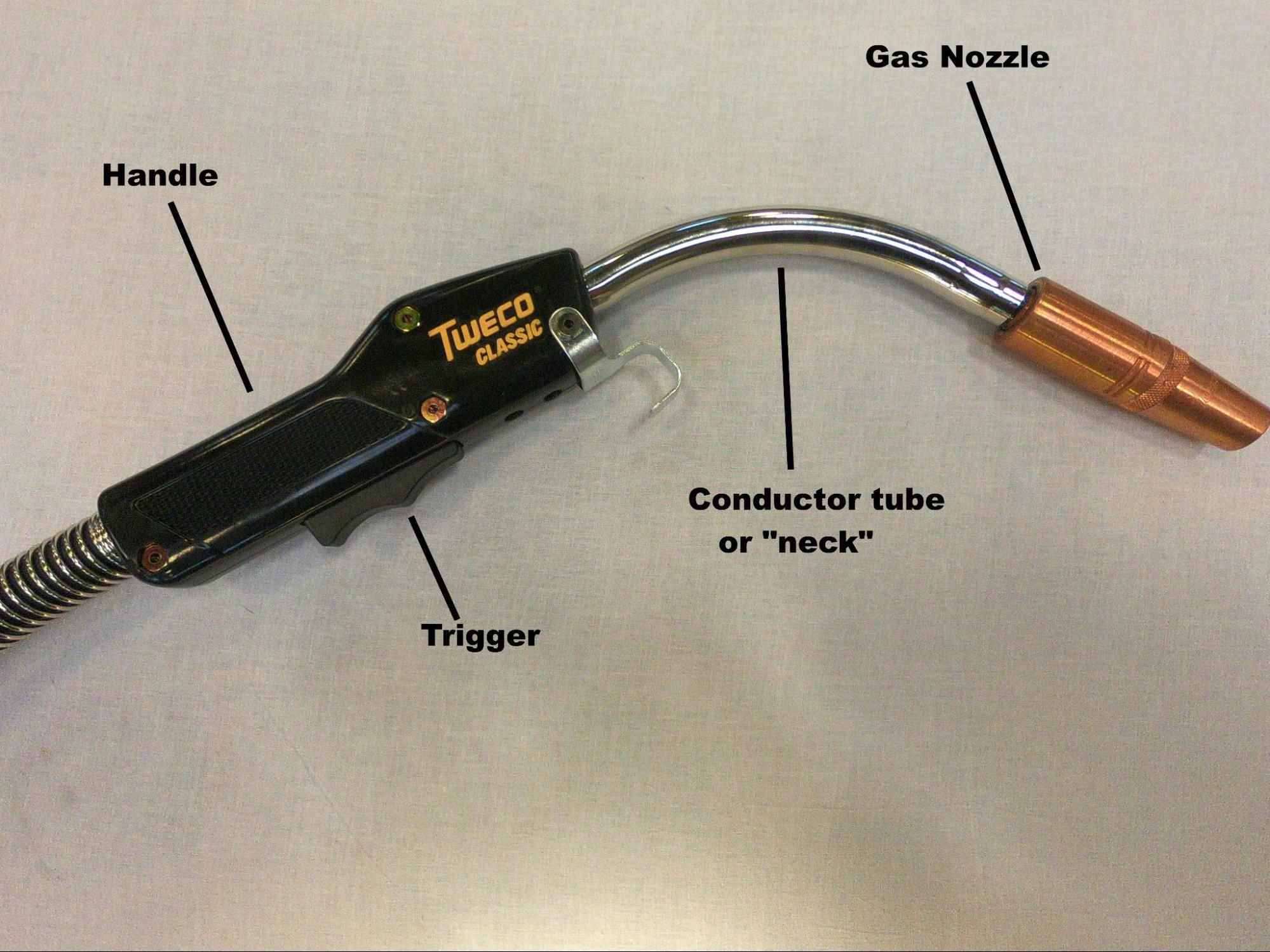
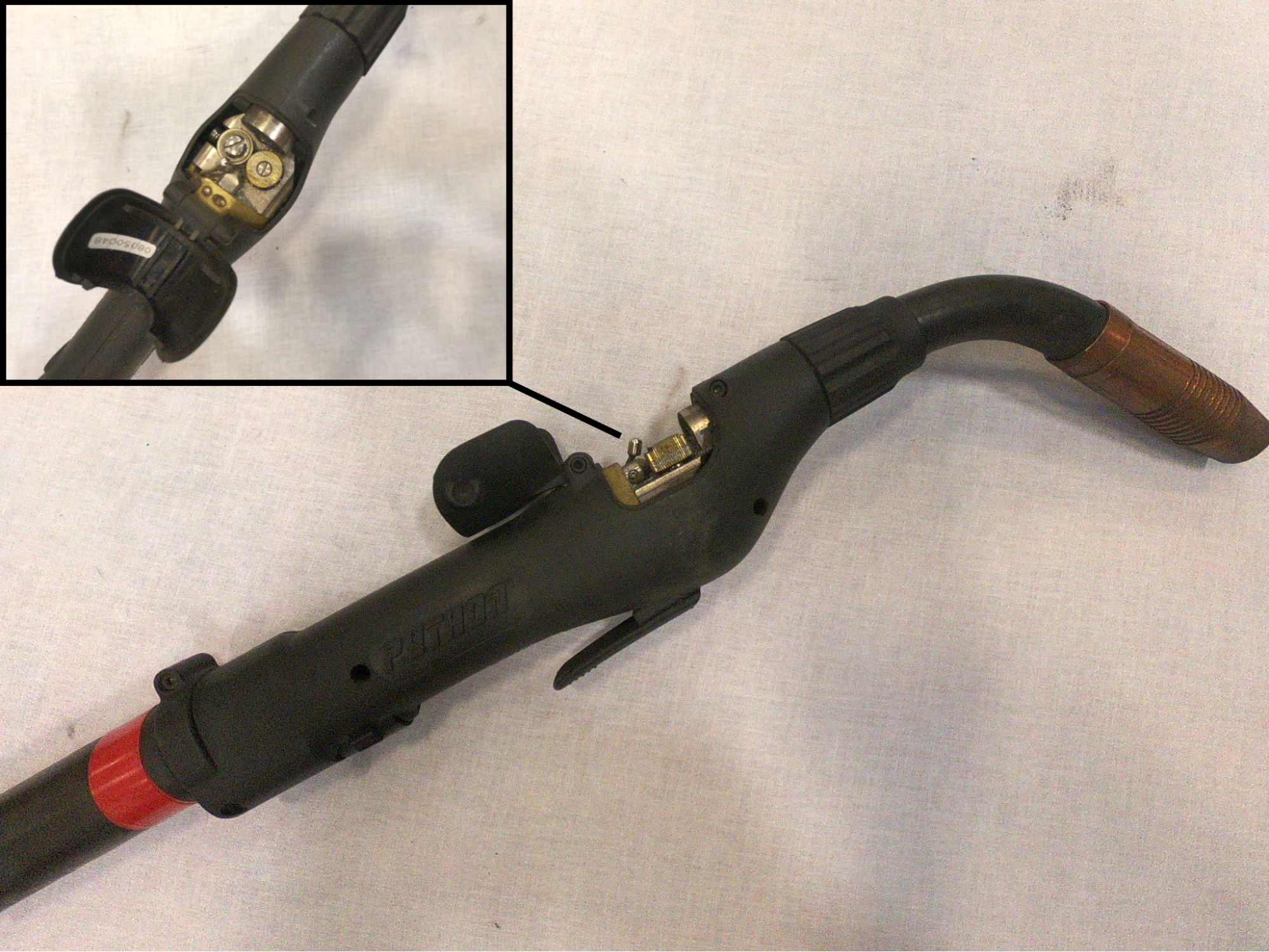
Welding guns, informally referred to as torches or whips, come in a number of configurations from many manufacturers. The primary function of the gun and cable is to conduct the electrode, shielding gas, and welding current from the wire feeding unit to the weld pool. The welding gun insulates the welder's hand from the welding current and allows them to direct and manipulate the wire electrode. It is especially worth discussing the different parts of the welding gun, as many items are consumable and must be replaced as they wear out.
The handle is typically a heavy-duty plastic that is non-conductive and heat-resistant and serves to insulate the welder’s hands from electrical shock. A trigger, when activated by the welder, will send a signal to the wire feeder to push the electrode and complete the welding circuit. Handles for FCAW-S often have a metal heat-shield to further protect the welder’s hand. If the handle has technical problems, it should be serviced by a qualified technician.
The conductor tube, often simply called the neck, is a piece that screws into the handle. This tube conducts power, electrode, and shielding gas past the handle. Curved conductor tubes of various angles are usually used in semiautomatic applications, and it is more common to see straight conductor tubes in mechanized operations. Flexible conductor tubes and length extensions are also available. The tube must be replaced when it becomes worn, but with proper care it can have a very long service life.
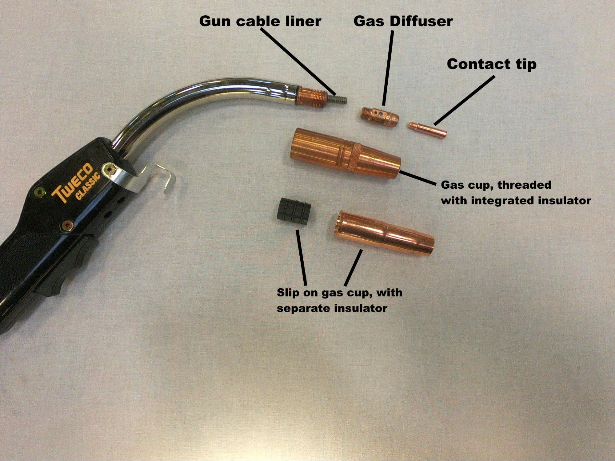
A gas diffuser, a consumable item, attaches to the conductor tube. Diffusers have a series of evenly spaced holes that distribute shielding gas evenly as it leaves the conductor tube. If you encounter porosity, the holes in the diffuser may have become clogged or misshapen. The diffuser also typically conducts power to the contact tip.
The contact tip is where the wire electrode becomes electrified. Contact tips are simply copper cylinders with holes through the center. The hole is sized according to the electrode diameter and must fit well to provide a good electrical connection. Over time, as the tip is heated and cooled repeatedly, the hole may become misshapen and prevent smooth wire feeding. A worn tip may be to blame if wire is not feeding or if the feeding is irregular.
The gas nozzle, or gas cup, directs the shielding gas towards the weld area. The nozzle acts like a shroud, covering the contact tip and gas diffuser. The nozzle must also be insulated from the welding circuit. The insulator, usually ceramic but always non-conductive, may be a separate piece that screws onto the conductor tube just below the gas diffuser, but many gas nozzles have integrated insulators. If the insulator fails, an electrical arc can jump between the base metal and gas nozzle, causing arc strikes. The nozzle should be cleaned regularly, as it will fill up with weld spatter. A pair of “welpers” or MIG pliers are useful for getting the job done. If the nozzle fills up with too much spatter, the flow of shielding gas will be impeded (causing porosity) or the gas nozzle may become electrified (causing arc strikes).
Like many components in the welding system, the welding gun will have an amperage rating. If the welding current exceeds the amperage rating of the gun, it will become overheated and rapidly deteriorate. Guns rated up to 400 amps are typically gas-cooled, meaning the flow of shielding gas through the gun is sufficient to keep it cool. Welding guns with higher amperage ratings tend to be liquid-cooled, such that coolant is circulated through the gun as it is operated. It is important to make sure coolant is present in the system and the coolant pump is running before operating those guns.
The cable of the welding gun contains a power cable to transmit the welding current, a gas line for shielding gas, and a liner through which the wire electrode is pushed. In the case of liquid-cooled torches, there will also be coolant-out and coolant-return lines. Of all the lines within the cable, there is one that you, the welder, may be expected to service: the cable liner the electrode moves through. As the wire is fed through the liner, it often introduces dust and debris to the liner and, over time, this will cause wire feeding issues. This can be prevented by installing cleaning and lubricating pads over the wire at the wire feeder, though the cable liner will still need to be cleaned and possibly replaced after a long enough time.
There is another way in which the cable can lead to wire feeding issues. If, at any time during welding, you are experiencing erratic wire feeding, take a look at the cable. Does it have numerous sharp twists and turns in it? If so, this may be the source of the problem. Every tight turn in the gun cable makes it that much more difficult for the wire feeder to move the wire through the gun cable liner. Keep any curves in the cable large and gentle.
Workpiece Lead and Clamp
The workpiece lead and clamp, often collectively referred to as the ground clamp, connect the work to the welding circuit. Both the lead (cable) and clamp have amperage ratings, just as with the welding gun. If this rating is exceeded, the components will rapidly heat up and deteriorate.
FCAW is a welding process that uses direct current (DC) electricity. These processes are susceptible to arc blow, which is an unstable welding arc caused by the strong magnetic force produced by the welding circuit. Arc blow can be a difficult issue to solve; however, moving the workpiece clamp to a different location will often be enough to help minimize or eliminate it. Additionally, slowing the wire feed rate will result in a lower welding amperage, which may also be helpful for this issue.
Wire-Feeding Unit
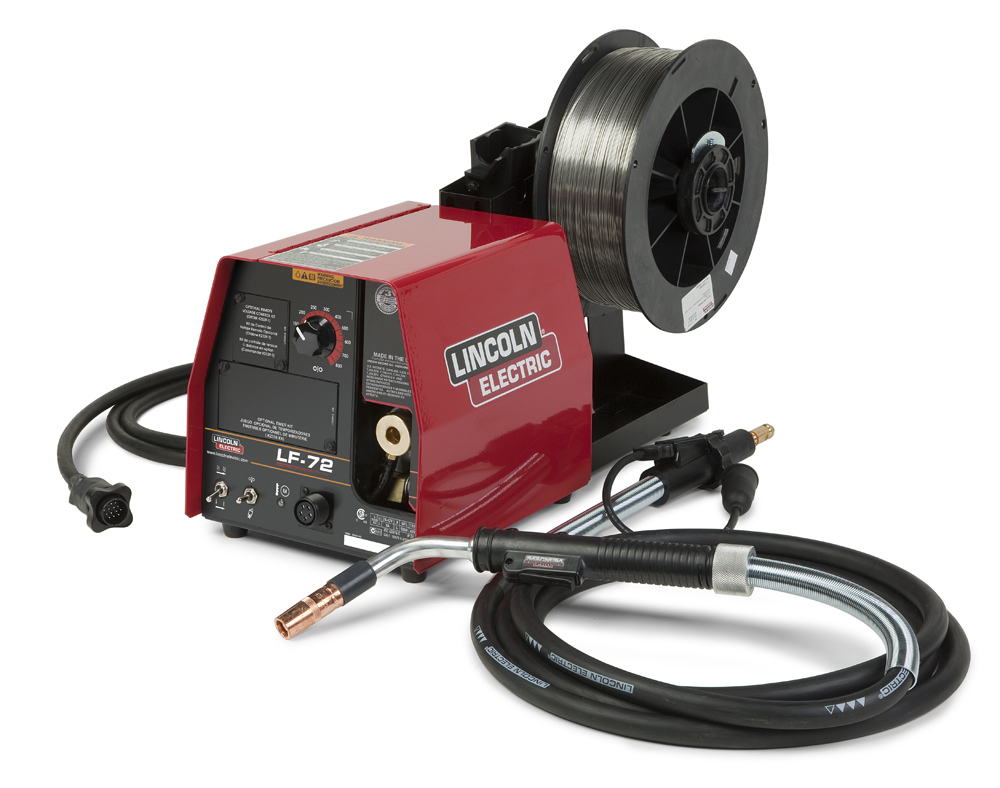
Wire feeders, which are really wire-feeding systems, can come in a number of different configurations. In industry, it is most common to see wire feeders as separate machines that are connected to the welding power source. The electrode lead will run from the negative or positive terminal on the welder to a power block inside the wire feeder, which will provide electricity for both the motor in the wire feeder and the welding circuit itself. Shielding gas, if necessary, will also be piped in from the cylinder or gas system to a connection in the wire feeder. The coil of wire electrode typically mounts to a spindle on the wire feeder and passes through a set (or sets) of drive rolls that push (and in some cases pull) the electrode through the gun cable, along with the shielding gas and electricity of the welding circuit.
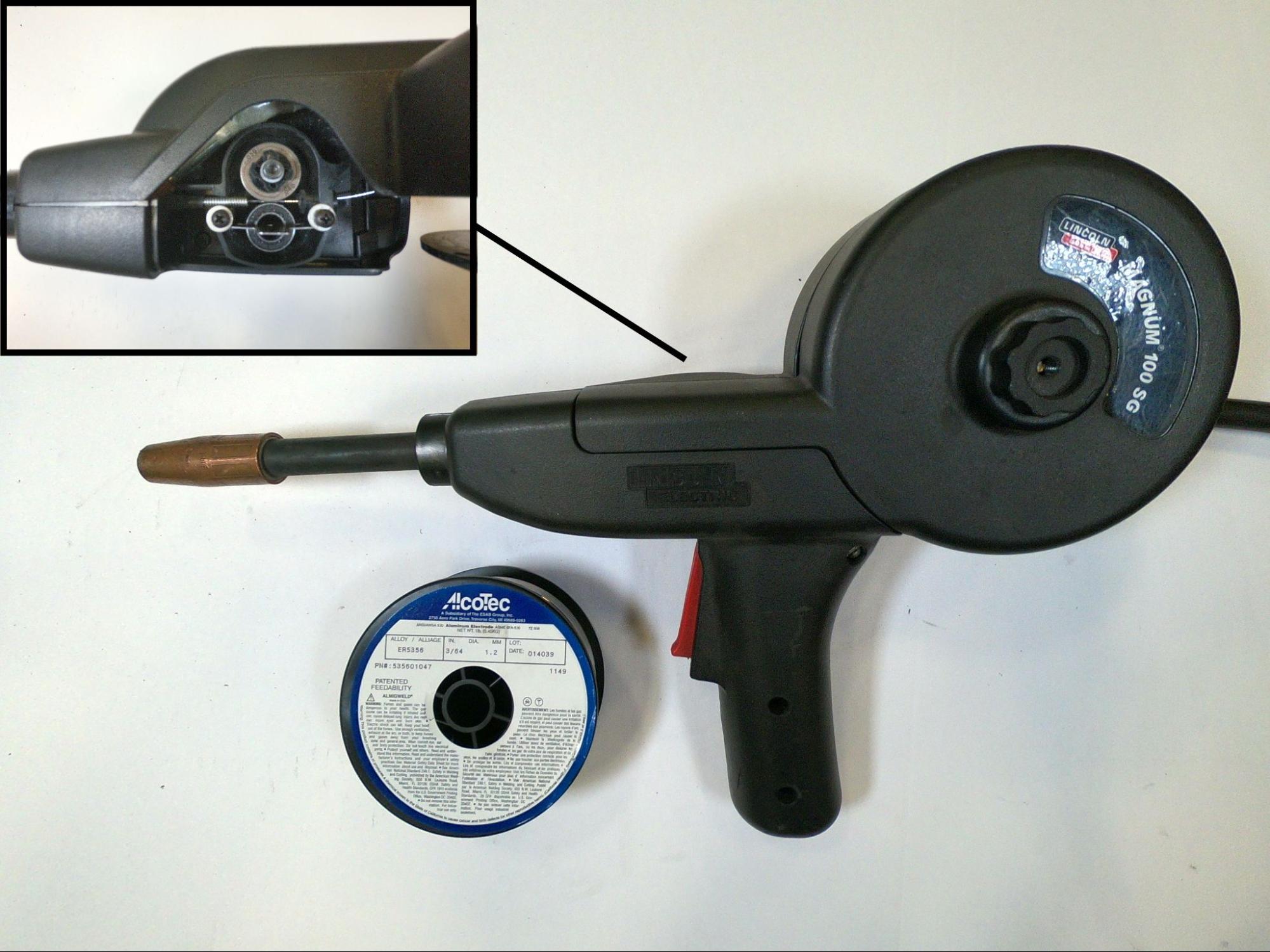
Although what was just described is the most common wire-feeding system, that is not the only way they may be encountered. Smaller welding power sources, meant for hobbyists or light-duty work, may have the welding machine and wire feeder integrated into one unit. In the case of push-pull systems, part of the wire-feeding system is integrated into the welding gun. In the case of spool guns, the entire wire-feeding system is integrated into the welding gun itself.
The primary function of the wire-feeding system is to feed the long coil of wire electrode to the welding area where it is melted off, transferred to the weld puddle, and then solidified into weld metal. The simplest and most common wire feeding system is a push-pull system. In this system a pair (or pairs) of motorized drive rolls, driven by an electric motor in the feeder, pull the coiled wire electrode off the spool and push it through the gun cable, which is activated by the trigger on the welding gun.
Wire feeders are complex machines, so if any serious repair is required a qualified technician should service the machine. However, there are parts that must be changed out, replaced, or adjusted on a routine basis, and it is a common expectation that the welders themselves will be able to recognize and service these items. Let’s cover some of those parts.
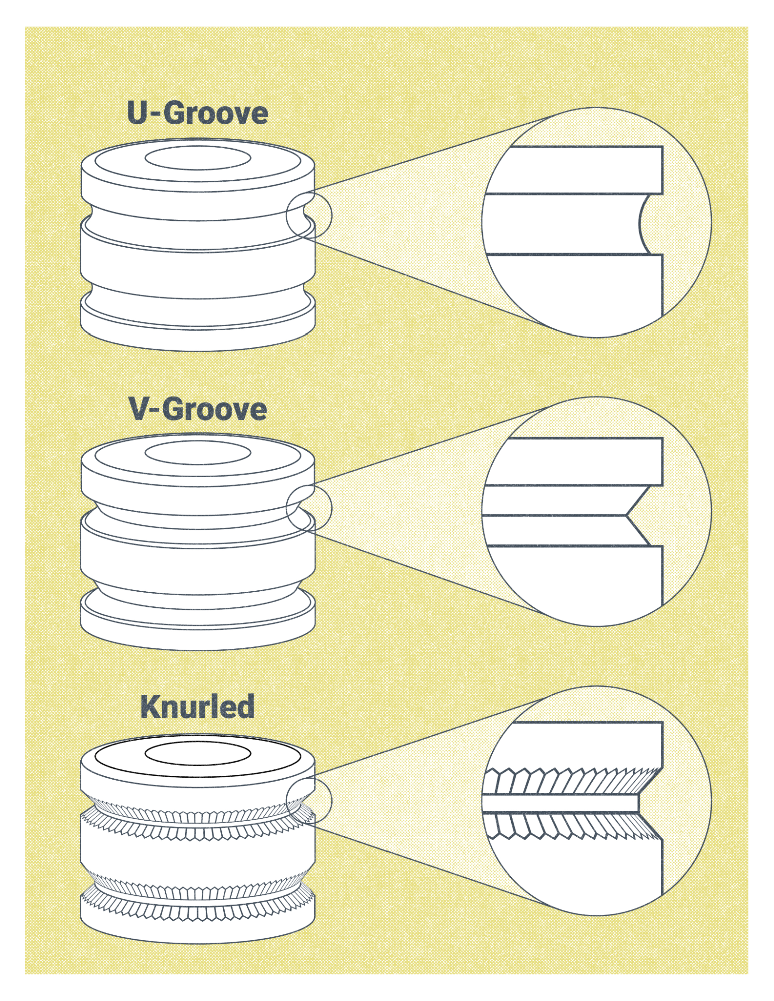
- Drive rolls are a pair of wheels with specifically sized grooves, and the wire electrode fits inside the grooves and is squeezed. The drive rolls are turned by a variable-speed motor, pushing the electrode through the gun cable. Their size corresponds with being designed to work with a specific diameter of electrode. Additionally, there are several types of grooves that drive rolls may have:
-
- V groove drive rolls are commonly used for steel electrodes, which have a solid composition
- U groove drive rolls are used with solid wire electrodes that are soft, like aluminum, and may be deformed if squeezed between V groove drive rolls. If the wire is deformed or squished out of its round shape, it makes it difficult or impossible to feed it through the gun cable and contact tip.
- Knurled drive rolls have small teeth in the grooves. This allows the drive rolls to grip and push the electrode without applying too much pressure. These rolls are used for FCAW, as those electrodes are not solid, but consist of a tubular sheath filled with flux.
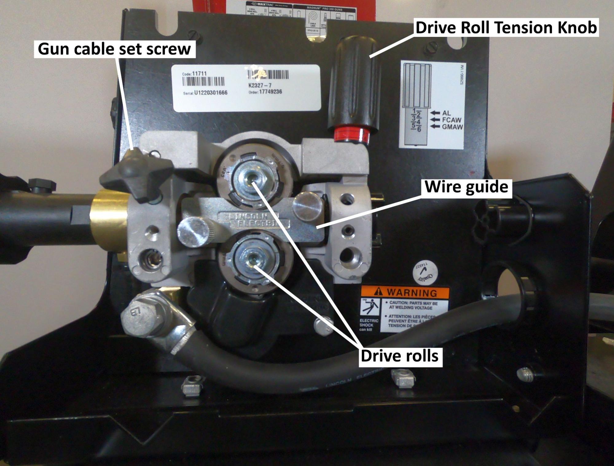
- The drive roll tension knob adjusts the pressure the drive rolls squeeze the electrode with. Too much tension deforms or damages the wire, leading to inconsistent feeding and introducing debris into the gun cable, while too little tension will cause the drive rolls to slip rather than push the wire.
- The wire guide ensures the wire accurately passes through the groove in the drive rolls. The wire feeder pictured in Figure 9.10 has a single guide that fits over the drive rolls. Other feeders may have two guides, one on the inlet and another on the outlet side of the drive rolls. Like drive rolls, wire guides are designed to work only with specific electrode diameters. Accordingly, a given electrode diameter must be used only with matching drive rolls and guides.
- The gun cable set screw secures the gun cable into a bushing in the wire feeder. This gun cable receiver bushing is where the electrode, power, and shielding gas enter the gun cable. This screw must be tightened securely to prevent the gun cable from working its way out of the wire feeder.
A push system is the simplest, most economical wire-feeding system and is the one most commonly employed for FCAW. Spool guns and push-pull systems are used when needed to feed particularly soft electrodes (like aluminum) or for very small diameter electrodes (0.023 inch and smaller), which have a high likelihood of bird-nesting, a phenomenon that occurs when the wire electrode folds over the top of itself rather than smoothly traveling through the gun cable. This results in a tangle of wire balling up near the drive rolls and must be removed before welding can continue.
Since FCAW is mostly used for welding thicker sections of steel, the process requires wire electrodes large and stiff enough to be fed with a push system. To ensure consistent wire feeding, a couple of things must be taken into consideration. First, the length of the gun cable should not be excessive. The longer the cable, the harder the wire feeder has to work; a 10-foot to 12-foot gun cable is common for most applications. Second, care should be taken to keep the gun cable straight, free of sharp twists and turns. This is relevant because the straighter the gun cable, the easier it is for the wire feeder to successfully push the electrode through the length of the gun cable.
There are many adjustments and settings on modern wire feeders. Some of these, like wire feed speed, are essential variables to the welding process. Others, like trigger interlock, make the work easier and increase operator appeal.
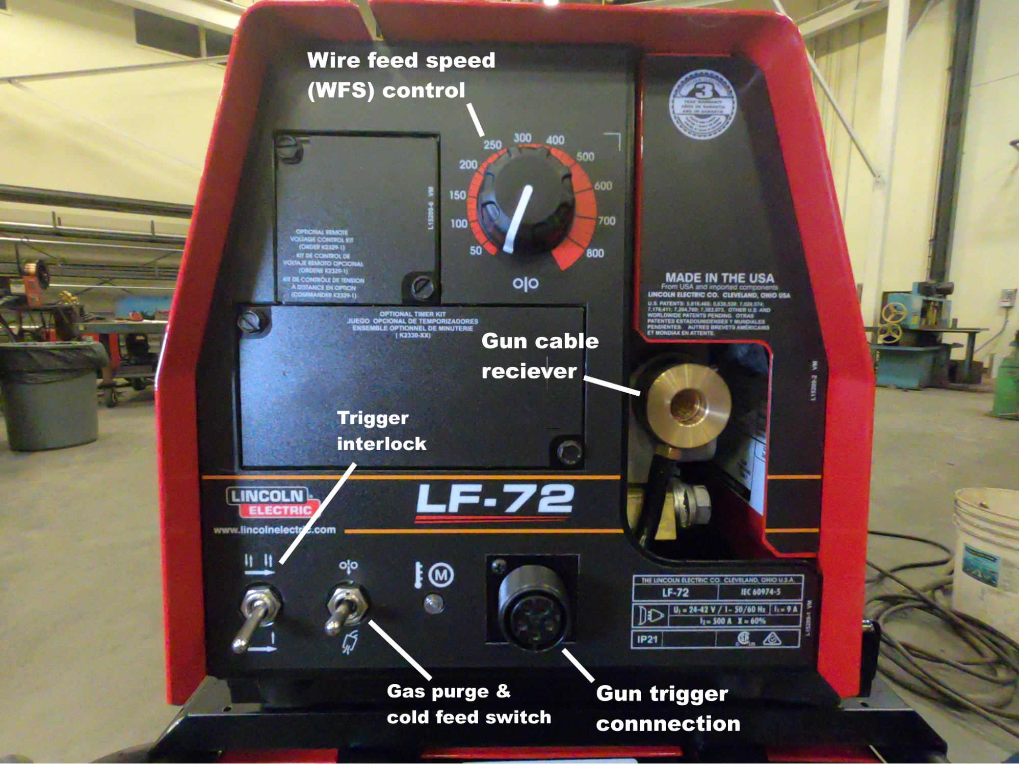
- Wire feed speed (WFS) is controlled by a knob that adjusts the voltage sent to the motor, which turns the drive rolls. In the U.S., wire speed is measured in inches per minute (IPM). On the wire feeder shown in Figure 9.12, the knob has a scale in IPM, but this is not always the case. Use this method to accurately determine wire speed: trim the wire flush with the gas nozzle, use a stopwatch to feed wire for exactly 15 seconds, then measure how many inches of wire fed out of the gun in that time, and multiply that by four. This will calculate the inches of wire fed per minute. WFS, in conjunction with the electrode diameter, determine the appropriate welding current or amperage.
- A gas purge and cold feed switch is common on most modern wire feeders. These are items of convenience. Cold feed, sometimes called jog, feeds wire without electrifying the welding circuit. It is helpful when fitting the machine with a new spool of electrode. The gas purge button pushes shielding gas through the system without feeding wire; it is used when adjusting gas flow rates or troubleshooting shielding gas problems.
- The trigger interlock switch changes how the gun trigger functions. Without trigger interlock, the gun trigger must be constantly held in place to continuously feed wire. With trigger interlock in place, the gun trigger functions with a toggle, the welder need only pull the trigger once to begin feeding wire and once again to stop the feeding. Trigger interlock can help reduce fatigue for your hands when making especially long welds.
- The gun cable receiver is a bushing where the gun cable attaches to the wire feeder and receives the electrode, power, and shielding gas.
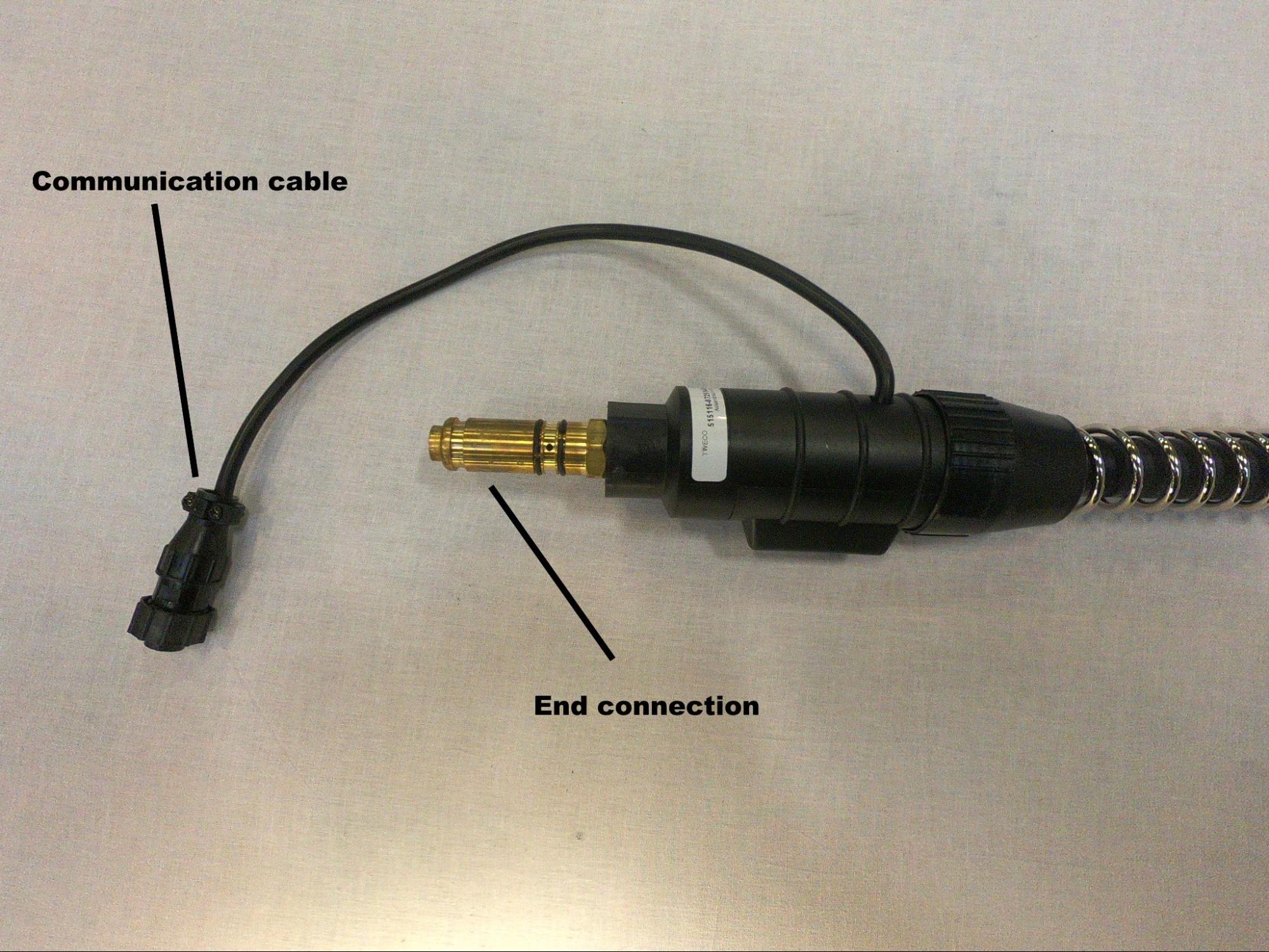
- The gun trigger connection is where a communication cable connects from the gun cable to the feeder. This allows the gun trigger to communicate with switches inside the feeder, which control the drive rolls, power, and shielding gas flow. On some feeders, this cable can easily come unplugged and is a good first inspection point if the wire feeder seems to stop working suddenly.
Setting Up the Welding System
The first step in setting up any arc welding system is getting power to the welding power source. This is as simple as plugging in the machine, but the circuit must have the proper voltage and amperage. Light- and medium-duty machines may plug into 110-volt or 220-volt circuits, respectively, and 20 or 30 amps on the circuit are common. Do not take these numbers at face value, though; the required electrical input for any welding machine will be specified by the manufacturer and listed on the machine itself or the owner’s manual. Heavy-duty machines commonly require a 480-volt, 50-amp circuit. These types of circuits have what is called three-phase power, a type of electrical power that is not typical to a home or outside of industrial environments.
Once power is supplied, the machine should be set up to run DCEP polarity . A properly sized power cable should be connected from the positive terminal of the machine to a terminal inside the wire feeding unit. The workpiece lead and clamp should be connected to the negative terminal of the welding machine. DCEP is overwhelmingly the norm for FCAW, but there are a few wire electrodes that should be used with DCEN; in any case, always follow the electrode manufacturer’s recommendations
The next step is to turn your attention to the wire feeder. If you’ll be using FCAW-G, you will need a supply of external shielding gas to protect the molten weld puddle from atmospheric gasses properly. A cylinder of the proper shielding gas should be fitted with a regulator and flow meter. From the flow meter, a gas line is connected and run to a shielding gas inlet, usually located on the back of the wire feeder. The type of shielding gas used will depend on the material being welded. In this and all other cases, the high pressure cylinder of shielding gas should be anchored to the welding cart of a wall by a chain to prevent it from falling. If using FCAW-S, shielding gas is not required.
Then the wire feeder must be fitted with the proper drive rolls, wire inlet, and outlet guides. When installing these components, the diameter of the wire electrode must be considered, as these parts are made to accommodate specific wire sizes.
Next, the spool of wire electrode can be put on. The spool must be oriented so that the end of the wire rolls off the spool from the bottom. It is critical that once the end of the wire is freed from the spool frame you do not let go of it. If you do, the spool of wire will uncoil and create a huge mess, and it can be difficult or impossible to salvage the spool if this happens. Keeping hold of the wire, pass it through the inlet hole on the back of the feeder housing, then feed it through the wire guides and drive rolls, clamping the drive rolls onto the wire and securing them in place with the tension knob. Once the wire is clamped in the drive rolls there is no danger the spool will uncoil.
The wire can then be fed through the gun cable using the gun trigger or cold feed switch. When feeding new wire through the gun cable, the gas nozzle and contact tip should first be removed from the gun, as the wire can get hung up on the contact tip—but be sure to reinstall them once you are done. The gun cable should also be kept as straight as possible while you perform this step to ease the feeding of the wire.
With this completed, the system is ready to weld. Connect the workpiece clamp to the welding machine, and you can get to welding!
Attributions
- Figure 9.3: Major Pieces Of Equipment Used In The FCAW Process by Nicholas Malara, for WA Open ProfTech, © SBCTC, CC BY 4.0
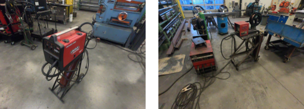
- Figure 9.4: Two FCAW Welding Systems by Cameron Kjeldgaard, for WA Open ProfTech, © SBCTC, CC BY 4.0
- Figure 9.5: Assembled Welding Gun by Cameron Kjeldgaard, for WA Open ProfTech, © SBCTC, CC BY 4.0
- Figure 9.6: Disassembled Welding Gun and Consumables by Cameron Kjeldgaard, for WA Open ProfTech, © SBCTC, CC BY 4.0
- Figure 9.7: FCAW Wire Feeder by Mgschuler is released under CC BY 3.0
- Figure 9.8: Spool Gun by Cameron Kjeldgaard, for WA Open ProfTech, © SBCTC, CC BY 4.0
- Figure 9.9: Push-Pull Welding Gun by Cameron Kjeldgaard, for WA Open ProfTech, © SBCTC, CC BY 4.0
- Figure 9.10: Wire Feeder, Interior by Cameron Kjeldgaard, for WA Open ProfTech, © SBCTC, CC BY 4.0
- Figure 9.11: Drive Rolls Used In Welding Wire Feeders by Nicholas Malara, for WA Open ProfTech, © SBCTC, CC BY 4.0
- Figure 9.12: Wire Feeder, Front by Cameron Kjeldgaard, for WA Open ProfTech, © SBCTC, CC BY 4.0
- Figure 9.13: Gun Cable End by Cameron Kjeldgaard, for WA Open ProfTech, © SBCTC, CC BY 4.0
Components
FCAW is a semiautomatic process, which has an impact on the complexity of the equipment involved. With welding processes that are considered manual, the equipment is usually solid-state; that is, there are no moving parts. In contrast, FCAW always involves a mechanical wire-feeding unit that feeds the electrode into the weld pool with the touch of a button (or, more typically, a trigger), which sharply increases productivity and reduces the required operator skill. The trade-off is a higher initial investment in the equipment and a more in-depth troubleshooting process to solve welding issues.
The major components necessary for the FCAW process include:
- Welding power source
- Welding gun and cable
- Workpiece lead and clamp (ground cable/clamp)
- Wire feeder
- External shielding gas (needed for FCAW-G but not FCAW-S)
- Flux-cored wire electrode
The rest of this section explores these components in depth, with the exception of electrodes and shielding gas, which have their own devoted sections.
Welding Power Source
Welding power sources for FCAW may come in the form of transformer rectifiers, though inverter machines—which are capable of multiple welding processes—are becoming the mainstay of the modern welding industry. These welding machines may range in size from compact light-duty units, with the wire feeder and power source integrated into one unit, to large engine-driven welder generators. In industrial applications, an FCAW power source will typically be heavy duty, capable of operating at 100% duty cycle at currents of up to 400 amps or more.
Power sources for FCAW must be capable of producing constant voltage (CV) output, sometimes referred to as constant potential (CP). CV machines produce a volt-amp curve that is nearly flat as opposed to constant current (CC), which produces a steeply sloped volt-amp curve. What this means for you, the welder, is that the welding arc will have small voltage changes and drastic amperage changes depending on your electrode extension. Also, unlike CC, CV processes do not give the welder direct control over welding amperage; instead, the welding voltage is controlled directly at the power source while the amperage is dependent on the wire feed speed and electrode diameter. These three things—voltage, wire feed speed, and electrode diameter—must all be selected in conjunction with each other for a smooth welding operation. It should be noted that many modern welding machines are capable of producing either a CV or CC output, so you won’t necessarily be using or avoiding specific machines. Note that alternating current (AC) should not be used with wire-fed processes like FCAW.
When selecting the polarity at the power source, it is important to check the recommended welding parameters for whatever electrode you will be using. While some of the most commonly used FCAW electrodes for steel operate on direct current electrode positive (DCEP), many are designed to run on direct current electrode negative (DCEN).
Welding Gun and Cable
Welding guns, informally referred to as torches or whips, come in a number of configurations from many manufacturers. The primary function of the gun and cable is to conduct the electrode, shielding gas, and welding current from the wire feeding unit to the weld pool. The welding gun insulates the welder's hand from the welding current and allows them to direct and manipulate the wire electrode. It is especially worth discussing the different parts of the welding gun, as many items are consumable and must be replaced as they wear out.
The handle is typically a heavy-duty plastic that is non-conductive and heat-resistant and serves to insulate the welder’s hands from electrical shock. A trigger, when activated by the welder, will send a signal to the wire feeder to push the electrode and complete the welding circuit. Handles for FCAW-S often have a metal heat-shield to further protect the welder’s hand. If the handle has technical problems, it should be serviced by a qualified technician.
The conductor tube, often simply called the neck, is a piece that screws into the handle. This tube conducts power, electrode, and shielding gas past the handle. Curved conductor tubes of various angles are usually used in semiautomatic applications, and it is more common to see straight conductor tubes in mechanized operations. Flexible conductor tubes and length extensions are also available. The tube must be replaced when it becomes worn, but with proper care it can have a very long service life.
A gas diffuser, a consumable item, attaches to the conductor tube. Diffusers have a series of evenly spaced holes that distribute shielding gas evenly as it leaves the conductor tube. If you encounter porosity, the holes in the diffuser may have become clogged or misshapen. The diffuser also typically conducts power to the contact tip.
The contact tip is where the wire electrode becomes electrified. Contact tips are simply copper cylinders with holes through the center. The hole is sized according to the electrode diameter and must fit well to provide a good electrical connection. Over time, as the tip is heated and cooled repeatedly, the hole may become misshapen and prevent smooth wire feeding. A worn tip may be to blame if wire is not feeding or if the feeding is irregular.
The gas nozzle, or gas cup, directs the shielding gas towards the weld area. The nozzle acts like a shroud, covering the contact tip and gas diffuser. The nozzle must also be insulated from the welding circuit. The insulator, usually ceramic but always non-conductive, may be a separate piece that screws onto the conductor tube just below the gas diffuser, but many gas nozzles have integrated insulators. If the insulator fails, an electrical arc can jump between the base metal and gas nozzle, causing arc strikes. The nozzle should be cleaned regularly, as it will fill up with weld spatter. A pair of “welpers” or MIG pliers are useful for getting the job done. If the nozzle fills up with too much spatter, the flow of shielding gas will be impeded (causing porosity) or the gas nozzle may become electrified (causing arc strikes).
Like many components in the welding system, the welding gun will have an amperage rating. If the welding current exceeds the amperage rating of the gun, it will become overheated and rapidly deteriorate. Guns rated up to 400 amps are typically gas-cooled, meaning the flow of shielding gas through the gun is sufficient to keep it cool. Welding guns with higher amperage ratings tend to be liquid-cooled, such that coolant is circulated through the gun as it is operated. It is important to make sure coolant is present in the system and the coolant pump is running before operating those guns.
The cable of the welding gun contains a power cable to transmit the welding current, a gas line for shielding gas, and a liner through which the wire electrode is pushed. In the case of liquid-cooled torches, there will also be coolant-out and coolant-return lines. Of all the lines within the cable, there is one that you, the welder, may be expected to service: the cable liner the electrode moves through. As the wire is fed through the liner, it often introduces dust and debris to the liner and, over time, this will cause wire feeding issues. This can be prevented by installing cleaning and lubricating pads over the wire at the wire feeder, though the cable liner will still need to be cleaned and possibly replaced after a long enough time.
There is another way in which the cable can lead to wire feeding issues. If, at any time during welding, you are experiencing erratic wire feeding, take a look at the cable. Does it have numerous sharp twists and turns in it? If so, this may be the source of the problem. Every tight turn in the gun cable makes it that much more difficult for the wire feeder to move the wire through the gun cable liner. Keep any curves in the cable large and gentle.
Workpiece Lead and Clamp
The workpiece lead and clamp, often collectively referred to as the ground clamp, connect the work to the welding circuit. Both the lead (cable) and clamp have amperage ratings, just as with the welding gun. If this rating is exceeded, the components will rapidly heat up and deteriorate.
FCAW is a welding process that uses direct current (DC) electricity. These processes are susceptible to arc blow, which is an unstable welding arc caused by the strong magnetic force produced by the welding circuit. Arc blow can be a difficult issue to solve; however, moving the workpiece clamp to a different location will often be enough to help minimize or eliminate it. Additionally, slowing the wire feed rate will result in a lower welding amperage, which may also be helpful for this issue.
Wire-Feeding Unit
Wire feeders, which are really wire-feeding systems, can come in a number of different configurations. In industry, it is most common to see wire feeders as separate machines that are connected to the welding power source. The electrode lead will run from the negative or positive terminal on the welder to a power block inside the wire feeder, which will provide electricity for both the motor in the wire feeder and the welding circuit itself. Shielding gas, if necessary, will also be piped in from the cylinder or gas system to a connection in the wire feeder. The coil of wire electrode typically mounts to a spindle on the wire feeder and passes through a set (or sets) of drive rolls that push (and in some cases pull) the electrode through the gun cable, along with the shielding gas and electricity of the welding circuit.
Although what was just described is the most common wire-feeding system, that is not the only way they may be encountered. Smaller welding power sources, meant for hobbyists or light-duty work, may have the welding machine and wire feeder integrated into one unit. In the case of push-pull systems, part of the wire-feeding system is integrated into the welding gun. In the case of spool guns, the entire wire-feeding system is integrated into the welding gun itself.
The primary function of the wire-feeding system is to feed the long coil of wire electrode to the welding area where it is melted off, transferred to the weld puddle, and then solidified into weld metal. The simplest and most common wire feeding system is a push-pull system. In this system a pair (or pairs) of motorized drive rolls, driven by an electric motor in the feeder, pull the coiled wire electrode off the spool and push it through the gun cable, which is activated by the trigger on the welding gun.
Wire feeders are complex machines, so if any serious repair is required a qualified technician should service the machine. However, there are parts that must be changed out, replaced, or adjusted on a routine basis, and it is a common expectation that the welders themselves will be able to recognize and service these items. Let’s cover some of those parts.
- Drive rolls are a pair of wheels with specifically sized grooves, and the wire electrode fits inside the grooves and is squeezed. The drive rolls are turned by a variable-speed motor, pushing the electrode through the gun cable. Their size corresponds with being designed to work with a specific diameter of electrode. Additionally, there are several types of grooves that drive rolls may have:
-
- V groove drive rolls are commonly used for steel electrodes, which have a solid composition
- U groove drive rolls are used with solid wire electrodes that are soft, like aluminum, and may be deformed if squeezed between V groove drive rolls. If the wire is deformed or squished out of its round shape, it makes it difficult or impossible to feed it through the gun cable and contact tip.
- Knurled drive rolls have small teeth in the grooves. This allows the drive rolls to grip and push the electrode without applying too much pressure. These rolls are used for FCAW, as those electrodes are not solid, but consist of a tubular sheath filled with flux.
- The drive roll tension knob adjusts the pressure the drive rolls squeeze the electrode with. Too much tension deforms or damages the wire, leading to inconsistent feeding and introducing debris into the gun cable, while too little tension will cause the drive rolls to slip rather than push the wire.
- The wire guide ensures the wire accurately passes through the groove in the drive rolls. The wire feeder pictured in Figure 9.10 has a single guide that fits over the drive rolls. Other feeders may have two guides, one on the inlet and another on the outlet side of the drive rolls. Like drive rolls, wire guides are designed to work only with specific electrode diameters. Accordingly, a given electrode diameter must be used only with matching drive rolls and guides.
- The gun cable set screw secures the gun cable into a bushing in the wire feeder. This gun cable receiver bushing is where the electrode, power, and shielding gas enter the gun cable. This screw must be tightened securely to prevent the gun cable from working its way out of the wire feeder.
A push system is the simplest, most economical wire-feeding system and is the one most commonly employed for FCAW. Spool guns and push-pull systems are used when needed to feed particularly soft electrodes (like aluminum) or for very small diameter electrodes (0.023 inch and smaller), which have a high likelihood of bird-nesting, a phenomenon that occurs when the wire electrode folds over the top of itself rather than smoothly traveling through the gun cable. This results in a tangle of wire balling up near the drive rolls and must be removed before welding can continue.
Since FCAW is mostly used for welding thicker sections of steel, the process requires wire electrodes large and stiff enough to be fed with a push system. To ensure consistent wire feeding, a couple of things must be taken into consideration. First, the length of the gun cable should not be excessive. The longer the cable, the harder the wire feeder has to work; a 10-foot to 12-foot gun cable is common for most applications. Second, care should be taken to keep the gun cable straight, free of sharp twists and turns. This is relevant because the straighter the gun cable, the easier it is for the wire feeder to successfully push the electrode through the length of the gun cable.
There are many adjustments and settings on modern wire feeders. Some of these, like wire feed speed, are essential variables to the welding process. Others, like trigger interlock, make the work easier and increase operator appeal.
- Wire feed speed (WFS) is controlled by a knob that adjusts the voltage sent to the motor, which turns the drive rolls. In the U.S., wire speed is measured in inches per minute (IPM). On the wire feeder shown in Figure 9.12, the knob has a scale in IPM, but this is not always the case. Use this method to accurately determine wire speed: trim the wire flush with the gas nozzle, use a stopwatch to feed wire for exactly 15 seconds, then measure how many inches of wire fed out of the gun in that time, and multiply that by four. This will calculate the inches of wire fed per minute. WFS, in conjunction with the electrode diameter, determine the appropriate welding current or amperage.
- A gas purge and cold feed switch is common on most modern wire feeders. These are items of convenience. Cold feed, sometimes called jog, feeds wire without electrifying the welding circuit. It is helpful when fitting the machine with a new spool of electrode. The gas purge button pushes shielding gas through the system without feeding wire; it is used when adjusting gas flow rates or troubleshooting shielding gas problems.
- The trigger interlock switch changes how the gun trigger functions. Without trigger interlock, the gun trigger must be constantly held in place to continuously feed wire. With trigger interlock in place, the gun trigger functions with a toggle, the welder need only pull the trigger once to begin feeding wire and once again to stop the feeding. Trigger interlock can help reduce fatigue for your hands when making especially long welds.
- The gun cable receiver is a bushing where the gun cable attaches to the wire feeder and receives the electrode, power, and shielding gas.
- The gun trigger connection is where a communication cable connects from the gun cable to the feeder. This allows the gun trigger to communicate with switches inside the feeder, which control the drive rolls, power, and shielding gas flow. On some feeders, this cable can easily come unplugged and is a good first inspection point if the wire feeder seems to stop working suddenly.
Setting Up the Welding System
The first step in setting up any arc welding system is getting power to the welding power source. This is as simple as plugging in the machine, but the circuit must have the proper voltage and amperage. Light- and medium-duty machines may plug into 110-volt or 220-volt circuits, respectively, and 20 or 30 amps on the circuit are common. Do not take these numbers at face value, though; the required electrical input for any welding machine will be specified by the manufacturer and listed on the machine itself or the owner’s manual. Heavy-duty machines commonly require a 480-volt, 50-amp circuit. These types of circuits have what is called three-phase power, a type of electrical power that is not typical to a home or outside of industrial environments.
Once power is supplied, the machine should be set up to run DCEP polarity . A properly sized power cable should be connected from the positive terminal of the machine to a terminal inside the wire feeding unit. The workpiece lead and clamp should be connected to the negative terminal of the welding machine. DCEP is overwhelmingly the norm for FCAW, but there are a few wire electrodes that should be used with DCEN; in any case, always follow the electrode manufacturer’s recommendations
The next step is to turn your attention to the wire feeder. If you’ll be using FCAW-G, you will need a supply of external shielding gas to protect the molten weld puddle from atmospheric gasses properly. A cylinder of the proper shielding gas should be fitted with a regulator and flow meter. From the flow meter, a gas line is connected and run to a shielding gas inlet, usually located on the back of the wire feeder. The type of shielding gas used will depend on the material being welded. In this and all other cases, the high pressure cylinder of shielding gas should be anchored to the welding cart of a wall by a chain to prevent it from falling. If using FCAW-S, shielding gas is not required.
Then the wire feeder must be fitted with the proper drive rolls, wire inlet, and outlet guides. When installing these components, the diameter of the wire electrode must be considered, as these parts are made to accommodate specific wire sizes.
Next, the spool of wire electrode can be put on. The spool must be oriented so that the end of the wire rolls off the spool from the bottom. It is critical that once the end of the wire is freed from the spool frame you do not let go of it. If you do, the spool of wire will uncoil and create a huge mess, and it can be difficult or impossible to salvage the spool if this happens. Keeping hold of the wire, pass it through the inlet hole on the back of the feeder housing, then feed it through the wire guides and drive rolls, clamping the drive rolls onto the wire and securing them in place with the tension knob. Once the wire is clamped in the drive rolls there is no danger the spool will uncoil.
The wire can then be fed through the gun cable using the gun trigger or cold feed switch. When feeding new wire through the gun cable, the gas nozzle and contact tip should first be removed from the gun, as the wire can get hung up on the contact tip—but be sure to reinstall them once you are done. The gun cable should also be kept as straight as possible while you perform this step to ease the feeding of the wire.
With this completed, the system is ready to weld. Connect the workpiece clamp to the welding machine, and you can get to welding!
Attributions
- Figure 9.3: Major Pieces Of Equipment Used In The FCAW Process by Nicholas Malara, for WA Open ProfTech, © SBCTC, CC BY 4.0
- Figure 9.4: Two FCAW Welding Systems by Cameron Kjeldgaard, for WA Open ProfTech, © SBCTC, CC BY 4.0
- Figure 9.5: Assembled Welding Gun by Cameron Kjeldgaard, for WA Open ProfTech, © SBCTC, CC BY 4.0
- Figure 9.6: Disassembled Welding Gun and Consumables by Cameron Kjeldgaard, for WA Open ProfTech, © SBCTC, CC BY 4.0
- Figure 9.7: FCAW Wire Feeder by Mgschuler is released under CC BY 3.0
- Figure 9.8: Spool Gun by Cameron Kjeldgaard, for WA Open ProfTech, © SBCTC, CC BY 4.0
- Figure 9.9: Push-Pull Welding Gun by Cameron Kjeldgaard, for WA Open ProfTech, © SBCTC, CC BY 4.0
- Figure 9.10: Wire Feeder, Interior by Cameron Kjeldgaard, for WA Open ProfTech, © SBCTC, CC BY 4.0
- Figure 9.11: Drive Rolls Used In Welding Wire Feeders by Nicholas Malara, for WA Open ProfTech, © SBCTC, CC BY 4.0
- Figure 9.12: Wire Feeder, Front by Cameron Kjeldgaard, for WA Open ProfTech, © SBCTC, CC BY 4.0
- Figure 9.13: Gun Cable End by Cameron Kjeldgaard, for WA Open ProfTech, © SBCTC, CC BY 4.0
This section will introduce you to the general steps of developing a WPS so you are aware of the general process, however there are many details of WPS development that are beyond the scope of this chapter. It is important to note that this discussion is intended to be generic and not exact since different welding codes and fabrications have different requirements that will make those processes look different, however the basic process will be common to what is presented here.
Going back to the cooking examples, imagine you are hungry and want to make a meal, but you want to use the ingredients available to you at home. If you haven’t done this yourself before, you may have had friends or someone who loves to cook do this in front of you. First, a look at the ingredients that are available is done and ideas form as what to make. Inside their mind they are thinking through what they can cook, how best to cook it, and details about spices or processes such as on the stovetop, oven, or grill.
With welding a similar process occurs for code welds, where a fabrication is made to the requirements of a welding code. An engineer or senior certified welding inspector, depending upon the complexity of the build and familiarity with the type of fabrication will develop an initial educated guess as to what welding process, machine settings, and technique will create a successful weld. This information is written down on a preliminary WPS or pWPS, and a welder or welding operator will try it out while someone records the essential variables such as the important settings and characteristics of the weld on a Procedure Qualification Record (PQR). The sample weld is then visually inspected and mechanically tested. If it passes all of the requirements of visual and mechanical testing and the PQR is reviewed and accepted in accordance with the company procedures and the quality program, then the PQR is qualified.
Let’s look at each of these closer:
Preliminary Welding Procedure Specification
The preliminary welding procedure specification, or pWPS, is an initial educated guess at what the welding essential variables are, based upon the code being used, manufacturer’s recommendations and experience welding the same or similar material. If the material or process is not one that is often used by the company, a welding engineer will very likely research the joint design and setting needed to create a successful weld.
This information is then used by the welding or welding operator to create a weld. The PQR is then used to record the settings used.
Procedure Qualification Record
A pWPS provides a range for the essential variables that the welder or welding operator uses to create the weld. For example, if welding with SMAW, a range could be 90 to 110 amps. The welder would use a value within that range to perform the weld. As the welder is welding, another person would write down all of the essential information on a procedure qualification record, or PQR, to record the inputs used. A single value is typically written down for each essential variable, such as an average current used. This single value is important because welding codes will provide ranges of +/- X% (plus or minus the percentage) so a range can be listed on a WPS.
As a welder you may be asked to weld for the development of a PQR. It is common for companies to ask a relatively new welder to do the welding for a PQR because a newer welder will typically listen more and follow directions more easily than a welder that has been welding for a long time. If you weld for a PQR and it passes visual and mechanical testing, the welding codes typically make you a qualified welder for that weld. It is worth asking if your welding in support of the PQR has qualified you as a welder, as this could be mistakenly overlooked by those asking you to weld.
Welding Procedure Specification
The PQR is then used to create a Welding Procedure Specification (WPS). A single PQR can be used to create many WPSs depending upon the rules of the welding code being used. There are various reasons for creating multiple WPSs from one PQR. One reason is that different alloys might be welded, and creating many WPSs might make the WPS easier to read rather than containing many options. This will depend upon the company preferences. Another reason would be finer control of the welder's machine settings. The ranges that are developed from the PQR come from single values. If a welder uses the low end of voltage range for GMAW, and the high end of the range for wire feed speed, the welder is technically within the WPS; however those settings are likely not the best for success. A certain level of common welding sense that is learned by the welder is assumed.
Standard Welding Procedure Specification
Developing a PQR for a WPS is a time consuming and expensive process. The American Welding Society, American Society of Mechanical Engineers, and others have welding codes that allow for Standard Welding Procedure Specifications (SWPS) which are developed for common welding configurations of geometry, welding processes, base materials, and filler materials. A company will purchase an SWPS for an application that they wish to create WPSs for. The SWPS has the advantage of having the backing of the various welding codes and societies that allow them. This reduces liability of the company if something were not 100% with their PQR.
Development of welding cast aluminum
Cast aluminum like other cast products was originally welded using oxyfuel gas welding because that was the process that was available in the early days. Oxyacetylene and oxyhydrogen forms of OAW were used. To protect the aluminum weld a flux was used with OAW that was then removed to prevent corrosion of the weldment. With the invention of GTAW, OAW is rarely used for welding cast aluminum however it may be found in your career for non critical welds.
GTAW and GMAW are used today to weld cast aluminum similarly to their use for welding wrought aluminum.
Basics of welding cast aluminum
Cast aluminum like other cast products is welded for repairs at the foundry to fill in missing surfaces. It is also welded to repair cracks on castings that have been in service. Just like other castings, cleanliness is important because many casts are repairs of equipment that were used in service and could be covered in or soaked up oil, greases, fuels, and other hydrocarbons used to lubricate the machine parts or fuel the parts if it is an engine block, for example. You may not be able to remove all of the impurities but you must do the best that you can.
If you are repairing a casting, it is very important to identify the size of the repair. If you are repairing a crack in a casting you must determine how long the crack is. First clean the surface of the casting in the area of the crack by removing any paint but also being careful not to smear metal over the crack through mechanical removal of the paint. You can use dye penetrant tests if doing a repair at home and follow the instructions for timing of the application. The crack is likely longer than you can see with the naked eye, and the dye penetrant might show you a crack that is a few inches longer than first thought.
The next step is to end drill the cracks to prevent them from spreading any further. Drilling the ends of the cracks removes the sharp point of the crack and replaces it with a round hole. Structurally round holes do not allow a stress concentration to form and the stress flows around the hole. When you end drill the hole, make sure to countersink it so you can inspect the metal below the surface to see if the crack is extending below the surface.
Preheating aluminum is important due to the brittle nature of casts. The thermal conductivity, the ability of heat to travel through a material, is lower than other materials. Check to see what preheat is needed for your cast aluminum so thermal stresses can be reduced as much as possible in an effort to reduce the possibility of your cast repair failing due to cracking.
It is equally important to have all of your welding equipment and materials ready to go before preheating begins. That way once preheating is completed you are ready to start welding, and are not off spending 30 minutes looking for something while the part cools off. Preheating of casts costs money, and any additional preheating caused by delays means more money. As discussed with wrought aluminum, aluminum oxide forms quickly and you want to start welding shortly after cleaning and preheating. With all of the equipment for welding in place, you can begin preheating.
Due to the thermal stresses discussed above, it is very important to slowly and evenly heat up castings to their required preheat temperature. Larger casting generally requires more preheat than smaller ones, and castings with different sized parts sticking out from the main fabrication require more preheat also. Check the base material’s temperature often and use additional preheat to maintain the temperature as needed.
Now that the base materials have been prepped, welding should start immediately. If the heat of welding reveals new cracks in the casting, stop welding and address the crack as if it were an original crack. This will likely mean that the weldment will have to cool back down to room temperature. This must be done slowly. Air cooling is generally too fast. If you used an oven to heat the cast, place the weldment back into the turned off oven and allow it to cool inside. The thermal insulation of the oven will slow the cooling process. Welding blankets or burying the weldment in sand can also be used to slow the cooling process.
If using GTAW as the welding process, you will likely see a lot of junk and dirt floating to the surface of your weld pool. This is normal and you will not be able to remove all of this junk, however you can add more weld metal in an effort to coax the dirt out and replace it with sound weld metal. There are many good videos online that show what this junk looks like and how the welders in those videos handle it.
If you are interested in welding on cast aluminum, look for some old cast aluminum parts such as broken wheels or junk engine blocks in a shop. Many shops save materials “just in case” they are needed, you could be that “just in case” they had in mind in your journey to learn. Check online for manufacturers of cast aluminum and ask them for a tour of their facilities. This is a great way to network and get used to speaking with people in the manufacturing industry. You may be able to score some scrap cast aluminum to weld on. As always, also ask your welding instructor, there may be cast aluminum in the shop or a way to get some.
Uses of cast aluminum in industry today
Cast aluminum is used in industry in many applications where lightweight yet strong fabrications are needed. An aluminum engine block is a great example where a lighter engine block means less weight of the vehicle and improved fuel economy.
Drag racing cars are less concerned with fuel economy when racing a quarter mile, but they are concerned with shortening the time to the finish line, and aluminum engine blocks compared to iron or steel are lighter and result in faster acceleration. Figure 21.9 above has an image of an aluminum engine block.
Attributions
- Figure 21.9: A cylinder head made of lightweight, high-temperature ACMZ, a new suite of aluminum-based alloys developed by researchers at ORNL. © Jason Richards, Oak Ridge National Laboratory Used with permission. Courtesy of Oak Ridge National Laboratory, U.S. Dept. of Energy. ORNL Security & Privacy Notice
Lincoln, J. F. (1994). Procedure handbook of arc welding (13th edition). James F. Lincoln Arc Welding Foundation.
Welding is a skill that holds immense potential for creating and shaping, yet it is not without its share of risks and hazards. To embark on a welding journey with confidence and competence, it is crucial to navigate and mitigate common welding hazards effectively. By understanding these hazards and implementing appropriate safety measures, welders can ensure their well-being while achieving exceptional results. This reading presents a comprehensive guide to navigating common welding hazards and prioritizing safety in the welding environment.
Arc Flash and Electrical Shock
Arc flash and electrical shock are inherent dangers in welding, particularly during processes like Shielded Metal Arc Welding (SMAW) and Gas Metal Arc Welding (GMAW). The intense light emitted during welding can cause arc flash, potentially leading to eye injuries. Furthermore, improper handling of electrical equipment can result in electrical shock. To navigate these hazards:
- Utilize proper welding helmets with auto-darkening filters to shield your eyes from arc flash.
- Wear dry and insulating gloves and protective clothing to minimize the risk of electrical shock.
- Inspect cables, connectors, and electrical equipment for damage before use, and avoid water or damp areas while welding.
Fire and Explosions
Welding generates extreme heat, sparks, and molten metal, all of which pose a fire hazard. Additionally, when working with flammable materials or in confined spaces, the risk of explosions increases. To mitigate these hazards:
- Clear the work area of flammable materials, liquids, and gases before starting the welding process.
- Place fire-resistant blankets or screens around the welding area to prevent sparks from igniting nearby objects.
- Have a fire extinguisher readily available and ensure all workers know how to use it effectively.
Toxic Fumes and Gases
Welding produces fumes and gases that, if inhaled, can lead to respiratory issues and long-term health problems. Welders must be vigilant about controlling exposure to these hazardous substances. To address this concern:
- Work in well-ventilated areas, ideally with local exhaust ventilation to remove fumes and gases at the source.
- Wear proper respiratory protection, such as N95 respirators or powered air-purifying respirators, when working in confined spaces or areas with inadequate ventilation.
Burns and UV Radiation
The intense heat generated during welding can lead to severe burns on the skin and eyes. UV radiation emitted during welding can cause arc eye, a painful condition similar to sunburn. To protect against burns and UV radiation:
- Wear flame-resistant clothing, including long sleeves, pants, and leather aprons, to shield the skin.
- Employ appropriate welding helmets with shaded lenses to prevent arc eye and protect your eyes from harmful UV rays.
Noise and Hearing Damage
Welding processes produce noise levels that can lead to hearing damage over time. To safeguard your hearing:
- Wear hearing protection, such as earplugs or earmuffs, especially when engaged in prolonged welding tasks or working in noisy environments.
Navigating these common welding hazards necessitates not only awareness but also proactive measures. By following safety protocols, using appropriate personal protective equipment (PPE), and adhering to industry guidelines, welders can confidently tackle their projects while minimizing risks.
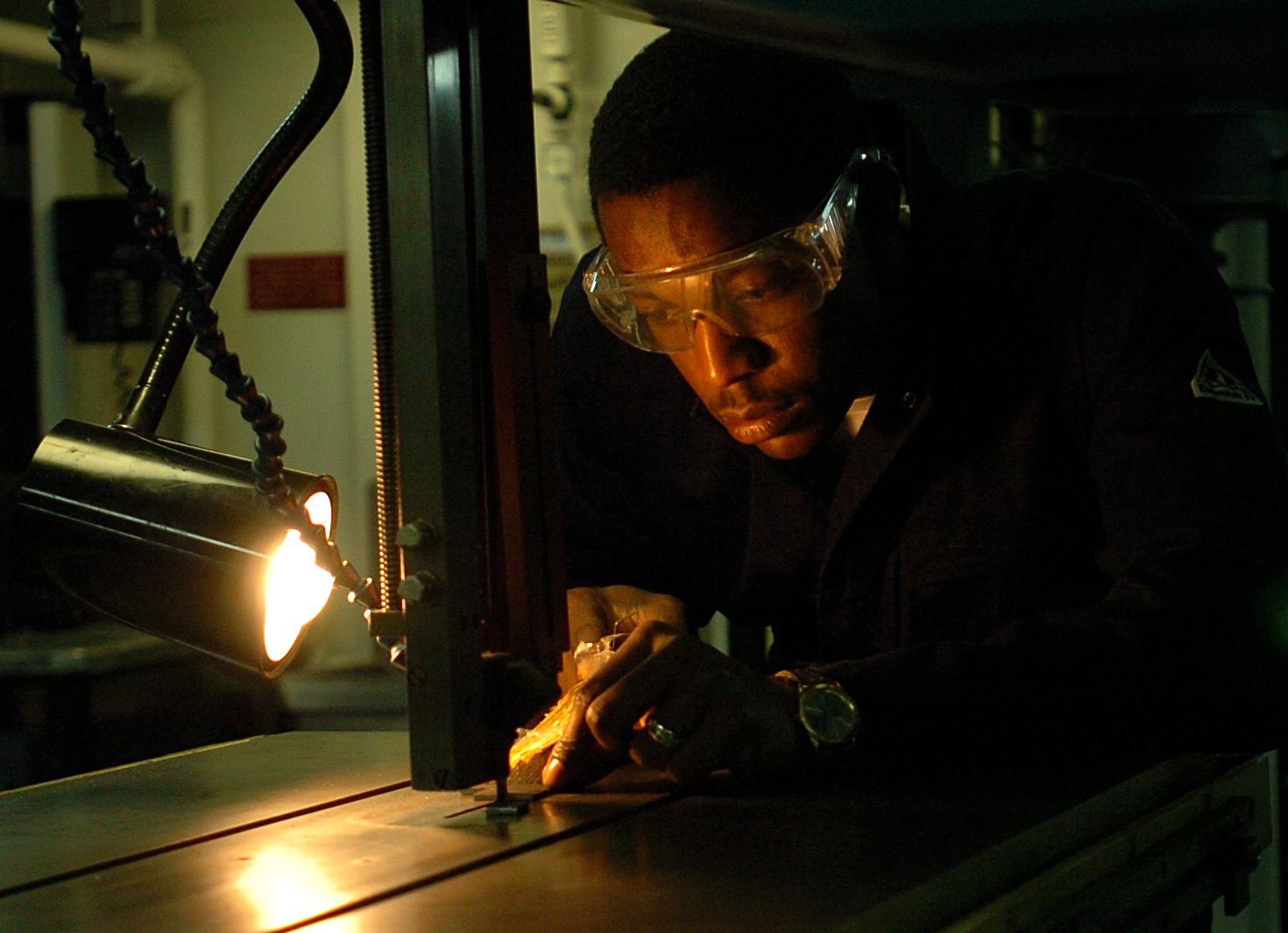
Overview
Consider this common scenario: A fitter surveys her blueprints. After determining the next part's location, she takes her layout tools and marks a line where the part should be placed on the assembly. She finds the correct pre-cut part and tests how well it fits between the parts that are already in place. It doesn’t fit; it is too long. She marks the correct length on the part by comparing it to the available space and, since it’s a fairly small aluminum part, she takes it to the band saw and trims it. After that, she takes it to the belt sander to touch up the cut edge. She returns to the assembly and once again tests the fit of the part. This time it fits like a glove.
As this scenario illustrates, the successful completion of a project relies on the fabricator’s ability to use their tools. Welders should know how to use a wide variety of tools. From simple hand tools like wrenches and pliers, to shop equipment such as drill presses or milling machines, tools are the foundation of the manufacturing industry.
In this chapter you will learn about a variety of tools and tool safety concepts. You will be introduced to many kinds of hand and power tools. We will cover the difference between different grades of shop tools and equipment. You will also be shown some basic fabrication techniques and concepts.
Objectives
After completing this chapter, you should be able to:
- List various hand tools.
- List various power tools and shop equipment.
- Differentiate between home/hobbyist and industrial shop tools and equipment.
- Recall various shop and tool safety concepts.
Key Terms
- Fabricator
- Fitting
- Fixture
- Kerf
- Layout
- Level
- Plumb
- Square
- Stock material
- Tack weld
- Tolerances
- True
- Weldment
Attributions
- Chapter opening image: US Navy 051215-N-7130B-027 Hull Maintenance Technician 2nd Class Matthew Stephens uses a vertical band saw to cut a piece of wood in the machine shop aboard the Nimitz-class aircraft carrier USS Ronald Reagan (CVN 76) by U.S. Navy photo by Photographer's Mate 3rd Class Aaron Burden in the Public Domain; United States government work
Development of welding non-ferrous metals
Whenever a new fabrication is being developed, the designers will look over existing materials to find ones that meet the mechanical properties required and the desired cost. In some cases the material that is needed for the application does not exist yet. This results in research being conducted to create new metal alloys. These application-specific alloys are why we have so many different alloys. New ferrous alloys are still being invented. However, for specialty applications such as space exploration with its need for high-strength, low-weight, and mechanical properties that can withstand large temperature swings, to high efficiency vehicles which require materials with a high strength-to-weight ratio and other applications with extreme in-service environments, non-ferrous metal alloys have and continue to be developed.
Non-ferrous alloys that are used in mass production in industry today that are weldable are usually welded using the main welding processes that you are learning in your welding labs: Gas Metal Arc Welding (GMAW), and Gas Tungsten Arc Welding (GTAW). GMAW is typically used for higher production fabrication needs if they can produce the quality required for the weldment, such as its use with Aluminum. GTAW is used for its exceptional quality and it can weld many more non-ferrous alloys than GMAW such as the Reactive Metals that will be discussed later in this chapter such as titanium and zirconium.
Low hydrogen electrodes are a must with ferrous metals when welding thick pieces of material or other materials that are subject to hydrogen induced cracking. Likewise, the filler metals’ chemical composition is equally important for welding non-ferrous metals with difficult weldability. For example, filler metal when welding pure aluminum is required because autogenous welds, meaning welds without filler metal, will crack. These filler metals were developed through careful research and trial and error before a workable filler metal alloy was found.
Luckily for us welders, companies are constantly developing better welding machines and better filler metals that make welding easier. For GMAW and GTAW, the welding power supplies are more complex than they used to be. Inverter technology for power supplies enables the welding machine to digitally control the electrical signal that is going to the welders torch or gun. Manufacturers of welding machines develop waveforms that they sell which are specific to the material being welded and the filler material. These waveforms get uploaded to the welding machine, through a usb stick, and the welding machine uses that waveform along with any other welder inputs to the machine such as material thickness, shielding gas etc, and the machine produces an electrical output that enables better welding. This is important for welding non-ferrous metals such as aluminum because it can provide more cleaning action to remove oxidation for those tougher welds. Or you can adjust the amount of penetration vs. cleaning action. This technology can also improve the arc start to make it easier for you to start welding. Chapter 5: Welding Machines covers welding machine power supplies in more detail.
Other welding processes that are beyond the scope of this book are also used to weld non-ferrous metals such as Electron Beam Welding (EBW), Laser Beam Welding (LBW), and Friction Stir Welding to name a few. These welding processes are typically performed by welding operators and not welders because they require precision that is not possible with a manual process and are automated processes. Welders perform manual and semi-automatic welding, while welding operators operate machines that perform automated welding such as welding processes that use robots.
Basics of welding non-ferrous metals
There are always exceptions to the rule, but generally speaking non-ferrous metals have a lower weldability than low carbon steels. Because steel has easy weldability and is less expensive than most alloys, usually that is the go to material. When an application needs to have higher strength, higher corrosion resistance, better ability to survive in-service conditions, or a higher strength to weight ratio, other metal alloys are used.
Non-ferrous materials like aluminum do not give off red light when heated to an elevated temperature like ferrous metals. This means that you can’t tell if a metal like aluminum is hot just by looking at it. This means that you need to know how the non-ferrous alloy will react to heating and if it will glow or not. The material's rate of expansion when heated becomes important because the alloy may shrink more than initially expected leading to higher stresses in the weldment and possibly cracking.
In addition, metals like aluminum oxidize very quickly. The rust on iron is oxidation; oxidation can flake off or remain on the metal. We prefer metals that form an oxide layer that remains to protect the underlying base material. The oxide layer on aluminum starts to form immediately after cleaning; if you take a break after cleaning your aluminum you should clean it again to remove any new oxide layer that formed.
Stainless steel wire brushes are typically used for cleaning and working with aluminum and titanium alloys. It is important to mark the handle of these tools with “Aluminum Only” or “Titanium Only” so you do not contaminate your metal by using the brush on another material.
Reactive metals react very strongly with oxygen and nitrogen, both of which are found in air, making the application of adequate shielding gas a must. Sometimes these metals are welded in a glove box so the entire environment of the weldment consists of the shielding gas. The welding glove box is a box with gloves attached that provides a barrier to the outside atmosphere but allows you to place your hands in the gloves to manipulate items in the box.
These non-ferrous alloys typically have specific alloying elements that give the metals their unique properties. This makes the selection of filler metals very important. The WPS for welding non-ferrous metals needs to be followed even more carefully because non-ferrous alloys, especially reactive metals, are much less forgiving to mistakes and/or contamination.
Uses of non-ferrous metals in industry today
Non-ferrous metals such as Aluminum are used for electrical and structural applications due to its high strength to weight ratio. Reactive metals, such as titanium, zirconium, and beryllium are used in harsh environments with corrosive or radioactive substances.
Titanium has an excellent strength to weight ratio, making it an alloy used in the aerospace industry, and it has high corrosion resistance making it a good choice for desalination parts to obtain clean drinking water from sea water. Due to titanium’s corrosion resistance, or lack of reaction to water, titanium is used in medical and dental implants.
Zirconium is used by the nuclear industry in nuclear power plants, especially for the tubes that hold the ceramic fuel pellets because it performs well in high temperature high radiation environments. Zirconium, like titanium, is also highly corrosion resistant and is used in medical and dental implants.
Beryllium is a high strength, highly corrosive resistant metal that is used in the nuclear, aviation, and space industries. This is a highly poisonous metal that should only be fabricated by trained personnel. Undisturbed, the metal is ok to handle. It's the dust from machining that causes berylliosis of the lungs which is a life threatening disease. Your body will have an immune response to inhaled beryllium that could be immediate or take months or years to develop. Anytime you work with a new metal or material it is important that you understand what you are working with so you can safely produce fabrications and not cause unnecessary damage to your health.
