Want to create or adapt books like this? Learn more about how Pressbooks supports open publishing practices.
23 Hand Tools You May Encounter on the Job
Douglas Rupik, M.Ed., JIW
Common Hand Tools and Their Functions
(see Chapter 6 for a more thorough discussion on shop tools)
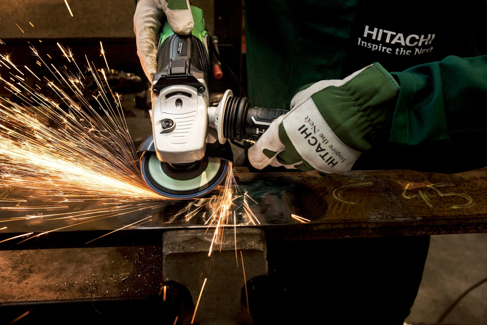
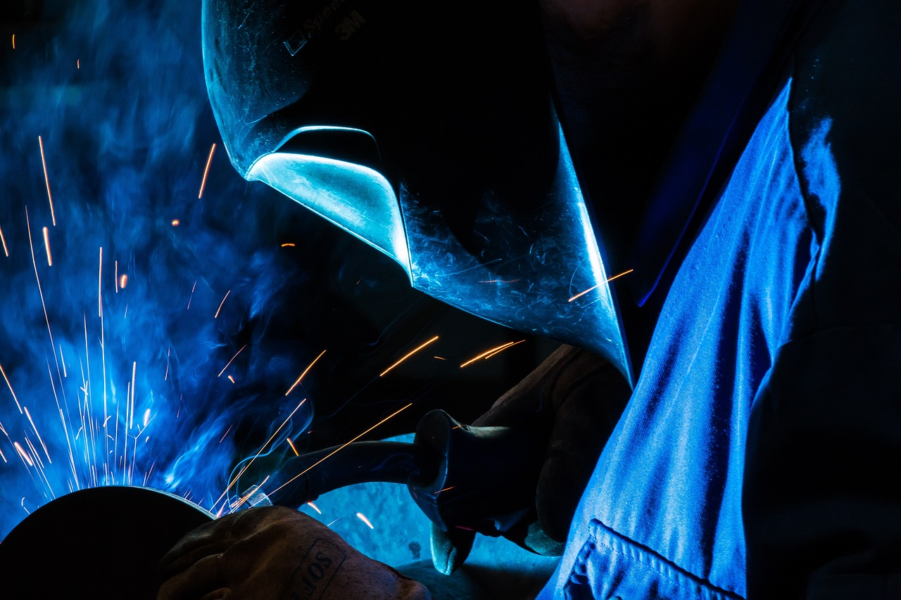
Figure 4.1. Sparks From An Angle Grinder / Photo Credit: Pixabay, Pexels License
After your welding machine, probably the most common tool you will use is an angle grinder. “Grinding and paint make me the welder I ain’t!” “Weld your best; grind the rest!” These jokes abound, but the truth is that electric and pneumatic angle grinders, end grinders, die grinders, and even bench grinders are indispensable tools for joint and surface preparation as well as weld cleaning and repair.
The next most common tool you’ll likely use is from the variety of hammers (chipping hammers, sledgehammers, engineer’s and shop hammers) and struck tools (chisels, punches, stamps, and wedges). A third category of hand tools we will discuss in this chapter are clamps such as C-clamps, bridge clamps, clamping pliers, and half clamps.
Why cover these tools? Because we are discussing safety, and these tools tend to cause more injuries on the job than soapstones and tape measures.
Safe Use of Welder-Specific Tools
First and foremost, only use tools in accordance with the manufacturer’s recommendations. This goes hand in hand with using the correct tool for the task at hand. For example, a screwdriver may seem like a good chisel or pry bar; however, it may chip when hit with a hammer and could send fragments into your eye or perhaps bend or break, and lead you to drop the heavy item it was supporting onto your hand or foot. Improper use of a tool may cause injury or damage to the workpiece.
Further, do not modify or remove a tool’s guards or other safety features. Tools are designed the way that they are partially because it makes for the best way to get a job completed as efficiently as possible while still being safe. Even though your tool modification idea may seem clever at the time, when you are seated on the witness stand in a courtroom explaining to a lawyer how the accident caused by your modification happened, your enthusiasm for the idea may fade a bit.
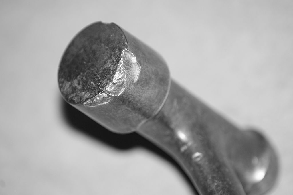
Figure 4.2. A Worn Out Hammer / Photo Credit: Wellcome Collections, CC BY 4.0Figure 4.3. Time To Replace This Hammer / Photo Credit: Noel Hankamer, CC BY-NC-SA 2.0
A third rule for the safe use of tools is that if a tool is or becomes damaged, immediately remove it from use. Have it repaired by a qualified service person or replace it. You may not appreciate this rule unless or until you are injured by a damaged tool.
And finally, always wear the appropriate PPE for the task you are performing.
Handheld Grinders
Handheld grinders may be powered by either electricity or pneumatics. Before using a grinder, always inspect the tool for damage. Is the power cord or air hose damaged? Its powerful supply of 110V of electricity and water can be fatal. Also, a one-inch diameter air supply hose that has a connection failure during use can subject you to a severe beating. Make sure all the safety features work, including any trigger guard mechanism, like a glade guard, and be sure the handle(s) are all in proper working order. Verify that the glade wheel is the proper one for the material you’ll grind and that it has the correct RPM rating for the grinder tool. Using an improper grinding wheel may cause it to break, which would send fragments flying and potentially cause severe injury.
When using a grinder, be aware of which way the wheel or blade rotates and understand how the grinder will react when under load. When you grind with it, which way does the tool want to move? It is not unheard of for a grinding wheel to catch and unexpectedly throw itself into the welder’s face. Make sure the handle is properly located and you have a good grip. Some handheld grinders generate 3.5 horsepower: that is similar to holding a running lawnmower engine in your hands.
Also, be sure you do not have loose or dangling clothing, hair, or jewelry that can get caught in the grinding wheel. A grinding wheel rotating at 4500 RPM will entangle itself in a hoodie’s drawstring and yank itself into your face before you can react. Unfortunately, this really happens. Never use a grinder without a guard and do not remove the guard.
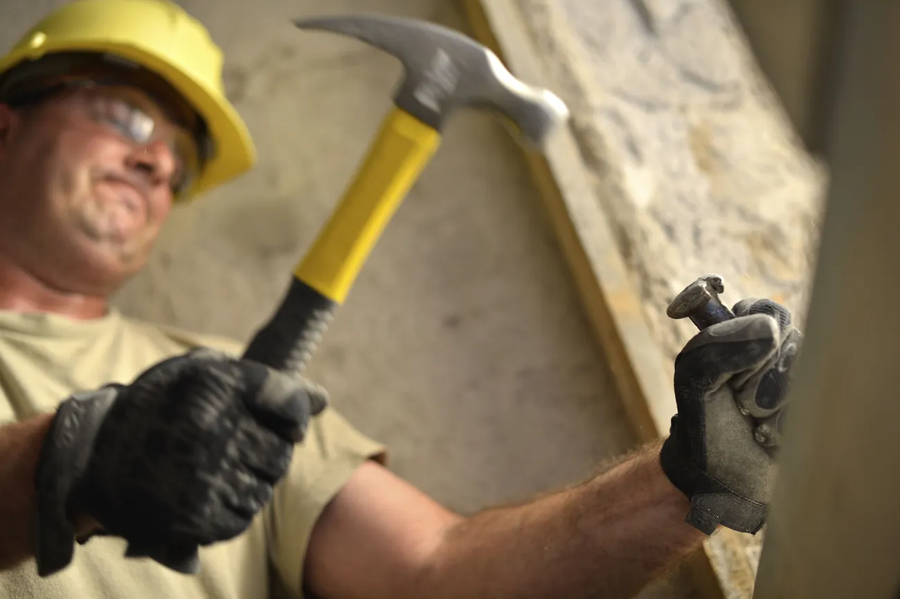
Hammers and Struck Tools
Welders very commonly use hammers and struck tools like punches, stamps, wedges, and chisels. While these are much less complicated than grinders and more on the level of Stone Age tools like rocks, they can still hurt you. I vividly remember working in a shop, swinging a four-pound hammer in one hand at a number stamp held in my other hand and accidentally smashing my thumb. After jumping around for a time, clutching my rapidly swelling thumb, I took a second attempt at stamping the number into my workpiece and hit my thumb again.
Figure 4.4. A Chisel With A Mushroom Head / Photo Credit: U.S. Department of Defense Current Photos, PD
Besides hitting yourself, the primary hazard you face when using hammers and struck items is the risk of fragments breaking off and becoming projectiles. Mushroomed heads on chisels, punches, and stamps may look like cool marks of usage, but they should be ground off before they break off. Be sure that any cracked or otherwise broken hammer handles are replaced. Do not tape them up and hope for the best. If working in an environment where sparks should be avoided, such as a refinery, be sure to use a brass hammer that does not produce sparks. And when using wedges, do not stack them on top of each other: pressure and force on them will increase and the stacked wedges will pop out at you. The more you have to pound them in, the harder they will hit you when they fly out.
Clamps
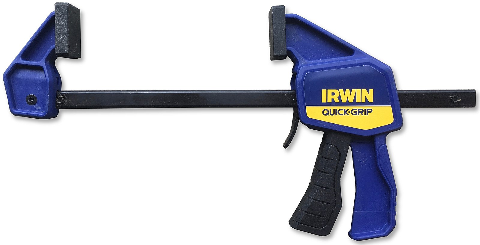
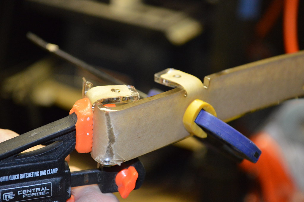
Figure 4.5. Inexpensive Bar Clamp / Photo Credit: J.C. Fields, CC BY-SA 3.0Figure 4.6. Clamps In Use / Photo Credit: zittware, CC BY-NC-ND 2.0
The hazard from using clamps—such as C-clamps, bridge clamps, half-clamps, and bar or pipe clamps—is the possibility of failure under load. Clamps are used to hold things in place and, sometime, to force things into place. They may suddenly fail when under a heavy load, which would mean parts flying out. This is especially dangerous when clamps are used to secure heavy components that may fall or shift if clamps fail. Never position yourself in any place that would put you in harm’s way if clamps were to fail.
Other safe practices to note are that bridge clamps, while especially strong, should never be used as an anchorage for fall protection. When clamping pieces together, be aware that surfaces that are not flat but rather at an angle, such as the legs of a channel, have a chance of slipping as pressure with the clamp is increased. And keep an eye out for a clamp that begins to bend and distort as you tighten: it is trying to warn you that danger is imminent.
Safe Use of Related Tools
The variety of hand tools and small power tools is quite wide, with new types of tools still being developed. With this in mind, keep these safety practices in mind regardless of what tool you are using:
Always use tools according to the manufacturer’s recommendations.
Never modify tools from their original configuration.
Use tools only for their intended purpose.
Repair or replace any damaged tool.
Above all, remember this: creativity and power tools are a bad combination. Only use tools for their intended purpose!
WABO vs. AWS: Understanding Welder Certifications in Washington State
For students preparing for a welding career in Washington State, understanding the difference between WABO and AWS certifications is essential. Both credentials are valuable, but they serve different purposes and are recognized in different contexts.
WABO stands for the Washington Association of Building Officials. WABO certification is designed specifically for structural welding work regulated by Washington State building codes. It is a highly controlled and verified process: testing is only conducted at WABO-accredited facilities by certified WABO examiners. Welders who pass receive a plastic WABO card, similar to a credit card, which lists their qualifications. This card is renewable annually and includes a strict continuity requirement, meaning welders must submit verification that they have used their certified skills regularly.
Because WABO is Washington-specific, it is often required for public infrastructure projects such as bridges and buildings within the state. Employers and inspectors can verify WABO credentials quickly, adding a layer of accountability and trust.
AWS, or the American Welding Society, offers a broader, nationally recognized certification system. AWS credentials, especially when earned through an Accredited Test Facility (ATF), are accepted across the U.S. and internationally. AWS certification is more flexible but may lack the centralized tracking that WABO offers unless taken through an ATF.
Which should you get? If you plan to work in Washington’s construction industry, especially on public or structural projects, WABO is a must. If you want to travel or work out of state, AWS provides wider access. Many professional welders earn both.
Ultimately, your goal should be to build the skills needed to pass either test—and be ready to retest with each new employer, since most require their own in-house exams.
A Welder in a Hood and Coveralls / Photo Credit: Benfe, Pixabay License
Overview
Anytime you are around welding, you may be exposed to a variety of hazards. These could involve a burn on your arm, a spark landing in your ear, a piece of metal dropping on your foot, or falling from a ladder.
Personal protective equipment is used to prevent and protect against these hazards. This equipment is used to safeguard your eyes, face, ears, hands, feet, lungs, and other parts of your body—and even protect you from falling risks.
This chapter will discuss common safety practices related to personal protective equipment you may use on the job. This information is not intended to take the place of employer safety training that may be required by law; rather, it is intended to emphasize the importance of following safe work practices at all times.
Objectives
After completing this chapter, students will be able to:
List and describe welding-specific personal protective equipment
List and describe general industry PPE
Explain why PPE is necessary
Key Terms
Personal protective equipment (PPE)
Occupational Safety and Health Administration (OSHA)
American National Standards Institute (ANSI)
Flash burn
Noise reduction rating (NRR)
National Institute for Occupational Safety and health (NIOSH)
The majority of carbon steels will come in shapes you are familiar with or will become familiar with while welding and fabricating. Plates, pipes, H-beams, and C-channel for example are common shapes you will use to fabricate. As a welder and fabricator, the WPS and blueprints will provide you with the instructions you need to complete the fabrication to the required specifications. If the WPS or blueprint has something that isn’t clear to you, stop and ask a colleague or supervisor for clarification. Spending a few minutes to clarify something is better than spending an hour or more on rework.
Steels can be hot rolled, cold rolled, quenched and tempered, or processed in other ways to achieve the desired properties. When you weld, you are destroying those treatments and mechanical workings of the base material because the metal melts within the weld pool returning the metal to its original state prior to treatment. In areas where the base material does not melt, there is a heat affected zone (HAZ) where grain growth, allotropic changes, and absorption of elements into the crystal structure can occur. The heat applied to the base metal in the HAZ will change the mechanical properties of the base material and/or result in a weld with material properties that are less than desired. The end result could be failure of the weld joint due to cracking which is why following a WPS is so important. If a structural failure occurs, as welders we want that failure to occur in the base material away from the weld and not because of the weld.
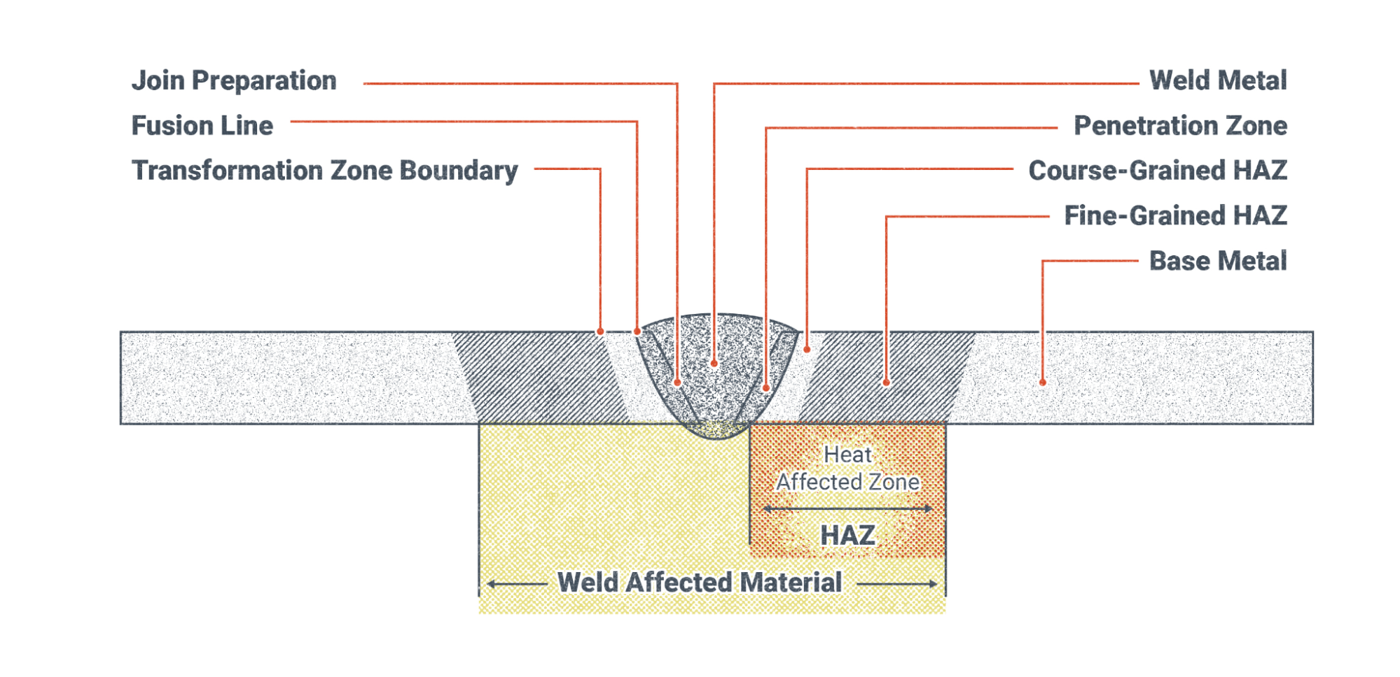
The HAZ is a complex set of sub zones shown in the V-Groove Butt Joint of Figure 20.6 below. The weld metal is at the center, followed by a penetration zone directly next to the weld metal which represents the melted base material that fuses with the weld metal. Moving further outward we next reach the coarse-grained HAZ that experiences elevated temperatures from welding but not hot enough to melt the metal. In this zone the heat causes the metal grains to grow becoming more coarse. The further away we move from the weld bead itself the less heat there is in the base metal due to dissipation of heat. The Fine-grained HAZ has grains that are affected by the heat but grow to a lesser extent. This zone may have been tempered from the heat. Outside of the fine grained HAZ is the base metal which may have been heated up, but has not undergone any mechanical property changes. It is important to note that other sources may break up the HAZ into a more detailed structure. For the purposes of this chapter, this level of detail in the HAZ is adequate.
Figure 20.6. Weld Heat Affected Zone / Photo Credit: Nicholas Malara, CC BY 4.0
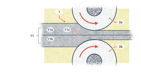
Steels from the mill are processed through cold and hot rolling. Rolling is a process where the steel is forced through rollers to flatten it out. Finer grained steel structures have a higher toughness. Figure 20.7 shows two metals being rolled together. The process for cold and hot rolling a single piece of steel is similar.
Figure 20.7. Rolling Cladded Steel / Photo Credit: Nicholas Malara, CC BY 4.0
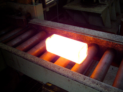
Figure 20.8 below shows a hot ingot that is being sent to a hot rolling process. This ingot of steel will be sent back and forth through a set of rollers that will gradually get closer together so the steel flattens out.
Figure 20.8. Hot Ingot Prior to Hot Rolling / Photo Credit: U.S. Department of Transportation, Federal Highway Administration, PD
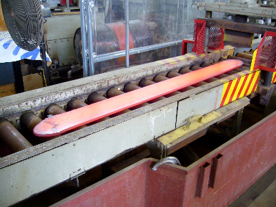
Figure 20.9 shows the results of the hot rolling process that has occurred to the ingot pictured in Figure 20.9.
Figure 20.9. Hot Ingot Being Hot Rolled / Photo Credit: U.S. Department of Transportation, Federal Highway Administration, PD
These cold and hot rolling processes break the larger grain structures into a finer grain structure. Welding on steels that have been cold or hot rolled to form finer grains will result in a coarse grain structure in the HAZ. Post Weld Heat Treatment (PWHT) will relieve some of the residual tensile stresses that exist from the weld metal shrinking after it cools. Temperatures for PWHT are carefully controlled in duration and magnitude based on the base material. Too high a temperature can transform the metal’s crystalline structure into something undesirable where there is a loss of strength, or being held for too long can cause grain growth which results in reduced toughness.
Because of these changes that occur due to the heat of welding to the surrounding base metal, it is important to follow all of the temperatures and other parameters and techniques listed on the WPS.
Whenever you are welding, you should generally know which metal or metal group you are welding on for a more successful weld. Ideally you would know the metal composition because the metal is labeled in one form or another, or can be determined by a device called a spectrometer which will analyze the metal by its light emissions. Figure 20.10 shows a similar but larger hand held spectrometer used for analyzing metal but is used to analyze pavement.
Figure 20.10. Hand Spectrometer / Photo Credit: U.S. Department of Transportation, Federal Highway Administration, PD
One property of metal which may be useful to the welder in identifying the type of steel they have in front of them is a file test. Table 20.1 contains information to help identify which type of steel you have based on its Brinell hardness which is one hardness scale used by metallurgists to rank the hardness of metals. The hardness of steel in Table 20.1 was able to be determined based on the hardness of a standard steel file with that of the metal being tested. Iron becomes steel with the addition of carbon.
Table 20.1. Approximate Hardness of Steel by the File Test
File Reaction
Brinell Hardness
Type of Steel
File bites easily into metal
100 BHN
Mild Steel
File bites into metal with pressure
200 BHN
Medium Carbon Steel
File does not bite into metal except with extreme pressure
300 BHN
High Alloy Steel - High Carbon Steel
Metal can only be filed with difficulty
400 BHN
Unhardened Tool Steel
File will mark metal but metal is nearly as hard as the file and filing is impractical
500 BHN
Hardened Tool Steel
Metal is harder than file
600 + BHN
Unable to determine
Note. From Operator's Circular Welding Theory And Application TC 9-237 (Table 7-6), by the U.S. Army (1993).
Table 20.2 lists the carbon contests of steel and cast iron for comparison.
Table 20.2. Carbon Content of Cast Iron Steel
Item
Approximate % of Carbon
Condition of Incorporated Carbon
Pig Iron
4
Free and Combined
White Cast Iron
3.5
Mostly Combined
Grey Cast Iron
2.5 to 4.5
0.6 to 0.9% free 2.6 to 2.9% combined
Malleable Cast Iron
2 to 3.5
Free and Combined
Tool Steel
0.9 to 1.7
All Combined
High Carbon Steel
0.5 to 0.9
All Combined
Medium Carbon Steel
0.3 to 0.5
All Combined
Cast Steel
0.15 to 0.6
All Combined
Low Carbon Steel
Up to 0.3
All Combined
Note. From Operator's Circular Welding Theory And Application TC 9-237 (Table 7-7), by the U.S. Army (1993).
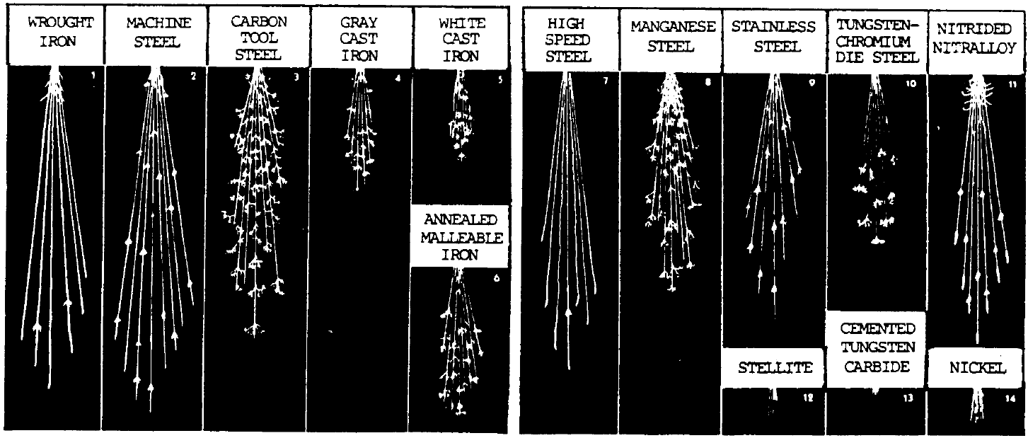
Another identification test that can be performed in the shop is a spark test that is conducted by grinding a metal sample on a grinding wheel and observing the sparks. Figure 20.11 below shows a black and white image of spark test results, color images are available online through an internet search.
Figure 20.11. Grinding Wheel Spark Test Results / Photo Credit: Headquarters, Department of the Army, PD
Lastly, the chip test is conducted by using a sharp cold chisel to remove material. Material may be small broken pieces or one long strip.
Table 20.4. Metal Identification
Metal
Chip Characteristics
White Cast Iron
Chips are small, brittle fragments. Chipped surfaces not smooth
Gray Cast Iron
Chips are about ⅛ inch in length. Metal not easily chipped; therefore, chips break off and prevent smooth cut
Wrought Iron
Low Carbon and Cast Steel
Chips have smooth edges. Metal is easily cut or chipped, and a chip can be taken off as a continuous strip
High Carbon Steel
Chips show a fine grain structure. Edges of chips are lighter in color than chips of low-carbon steel. Metal is hard but can be chipped in a continuous strip.
The table above describes the chip characteristics of different cast irons and steels. This is useful information if you have an unknown metal that you may think is cast iron or steel and are looking for a relatively easy way of determining its type.
Knowing the temperature of steel is important to a welder. Accurate measurements of metal surface temperatures can be taken using a hand held industrial infrared thermometer, using heat sticks to determine if the temperature has exceeded the value of the stick material, or by the least accurate method of visually observing the color of the steel. Table 20.5 below provides the colors steel may emit at different temperatures.
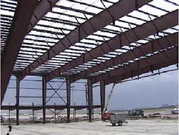
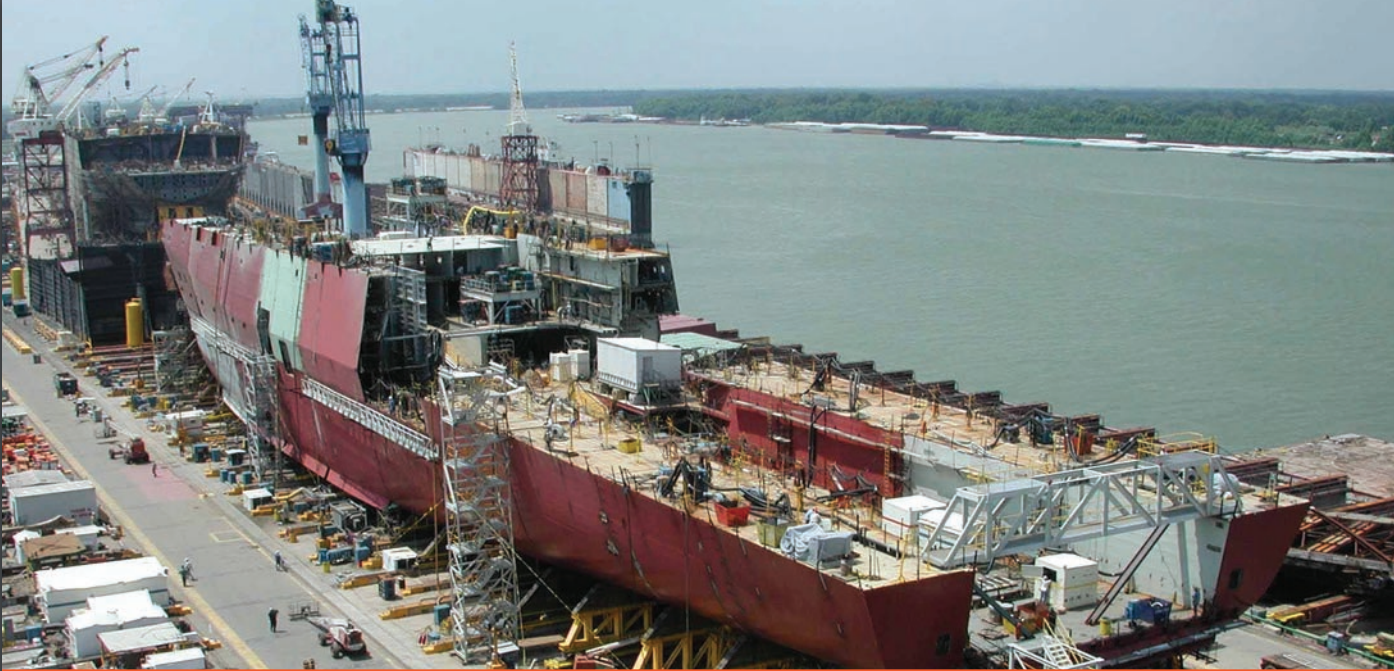
Everything from buildings, ships, bridges, railroads, cars and trucks, shelves, home appliances such as washing machines and dryers, water heaters, pressure vessels, tanks, pipes, and many more daily-used items that improve our everyday lives are made out of carbon steels or have carbon steel components.
Figure 20.12 below shows the uses of steel in a large building. Notice the size of the small trailer in the middle of the structure on the ground.
Figure 20.12. Steel Building / Photo Credit: U.S. Department of Labor, Occupational Safety and Health Administration, PD
Figure 20.13 below shows a steel ship being built.
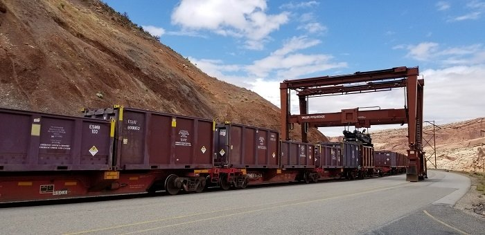
Figure 20.14 shows railcars and presumably a railroad that they are riding upon, which is also made of steel.
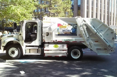
Figure 20.14. Steel Rail Cars & Containers / Photo Credit: U.S. Department of Energy, Office of Environmental Management, PDFigure 20.15. Steel Vehicles / Photo Credit: U.S. Department of Transportation, Federal Highway Administration, PD
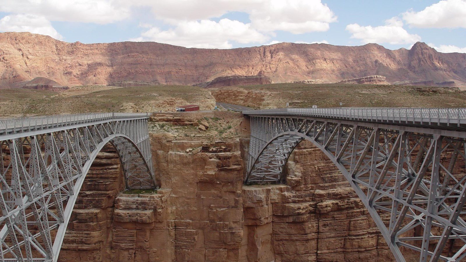
Other uses of steel are for cars and trucks. The sanitation truck in Figure 20.15 above is made of steel and is welded. Figure 20.17 shows two bridges, where the one on the left was built in the 1920’s while the one on the right was built in the 1990’s. Notice how the new bridge uses the same construction style to match the old bridge.
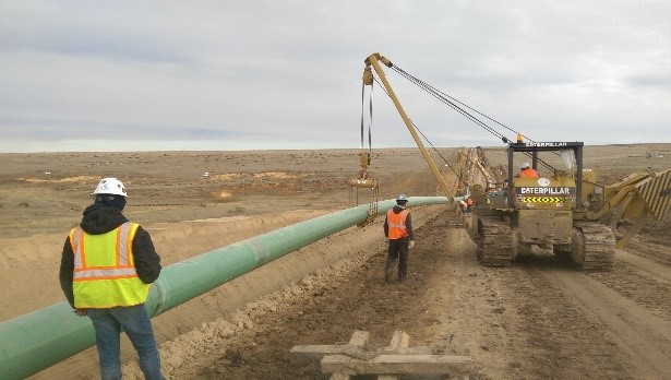
Figure 20.16. Steel Bridges / Photo Credit: U.S. Department of the Interior, National Park Service, PDFigure 20.17. Steel Pipelines / Photo Credit: U.S. Department of Transportation, Pipeline and Hazardous Materials Safety Administration, PD
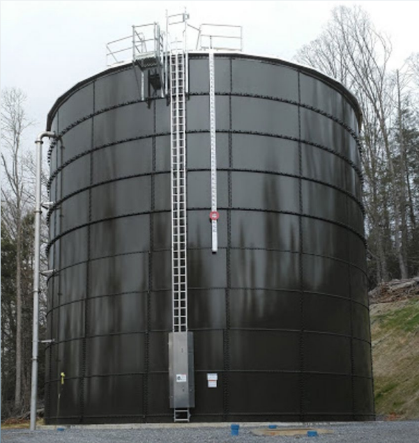
Figure 20.17 above shows a steel pipeline being constructed. Figure 20.19 below shows a steel water tank in green being used for the local towns water supply.
Figure 20.18. Steel Water Tank / Photo Credit: U.S. Environmental Protection Agency, Office of Ground Water and Drinking Water, PD
Welding processes used with carbon steels in industry today
The following list is not exhaustive but is a list with the welding processes you will encounter as a student in your technical program for welding carbon steels. Generally speaking all welding processes at your local community college or vocational school are applicable to welding carbon steels. Table 20.6 below offers a very general overview of how the processes are used, but remember there are always exceptions to generalizations.
Table 20.6. General Welding Process Uses
Welding Process
General Use
SMAW (Stick)
General Use: Fabrication in shop and field, repairs, tack welding
FCAW-G (Flux Cored Gas Shielded)
Fabrication in the shop, repair, used on dirtier parts
FCAW-S (Flux Cored Self-Shielded)
Fabrication in the field, repair
GMAW (MIG)
Fabrication and repair on clean surfaces
GMAW-S (MIG Short Circuit)
Fabrication and repair on clean thin surfaces
GTAW (TIG, Heliarc)
Fabrication and repair of all metals including welds requiring high quality such as specialty alloys and critical welds
SAW
Fabrication of thick materials in heavier industries such as bridge building, pipe fabrication, and very large fabrications.
Note. Heliarc is the original trade name by the Union Carbide Corporation
It is important that you learn to use as many welding processes as possible while in your welding program because many processes are used together in industry such as using GTAW for root passes followed by SMAW on pipe welding. These next few sections provide a high level overview of the welding processes. Please see the chapters on these welding processes for more information.
Shielded Metal Arc Welding (SMAW)
Shielded Metal Arc Welding is a tried and true welding process that has relatively inexpensive equipment that can get into tight spaces to weld. The process has various electrode types of different alloys, tensile strengths, and sometimes hydrogen contents. Low hydrogen electrodes are used for applications where cracking is an issue such as when welding thick base materials. If low hydrogen electrodes are not used, that hydrogen may not have enough time to diffuse out of the base material which could lead to cracks. Use of low hydrogen electrodes and even a post weld heat treatment may be used to reduce and remove hydrogen from the weldment. Chapter 8 discusses SMAW in detail.
Gas Metal Arc Welding (GMAW)
Gas Metal Arc Welding (GMAW) is a process that does not produce a slag, is a higher deposition process than SMAW meaning that it can lay down more weld. GMAW has the ability to deposit more weld metal than SMAW due to the filler wire being continuously fed into the welding gun with the pull of the trigger. The drawback of GMAW is that it suffers from being susceptible to air drafts which does not make it a good candidate for field welding. Air drafts will blow away the shielding gas that is needed to protect the weld metal while it is hot from the elements such as nitrogen and oxygen that are in the air which will result in porosity in the weld. Chapter 10 discusses GMAW in detail.
Flux Cored Arc Welding (FCAW)
Flux Cored Arc Welding is a semi automatic wire feed process that is being adopted by welders in the field. This process has a self shielded and a gas shielded variation. The self shielded FCAW, or FCAW-S, is similar to SMAW in that the electrode contains flux material that shields the weld from the air. The other variation is FCAW-G which uses a cored electrode that has a flux in it and a shielding gas which together protect the weld from the air.
One question that might be asked is “Can I use a FCAW-S wire with a shielding gas if I run out of FCAW-G wire?” You certainly could set up a machine to do this, but it is not advised because the elements that are in the FCAW-S wire will not react with the air to form a slag as they are intended and will instead end up in the weld pool which will likely negatively affect the chemistry of the weld and in turn the mechanical properties of the weldment. This is similar to hauling construction materials in a compact car vs. a truck; you can do it but unintended damage is likely to occur. If it is a code weld, you can not use FCAW-S wire because it is not listed on the FCAW-G WPS.
The benefits of using FCAW are that it has a higher deposition rate and it can be considered a low hydrogen process even though the hydrogen levels in the electrode are not as low as some low hydrogen SMAW electrodes. The downside to FCAW is that it may not have the versatility that SMAW has for tight spaces, and the welding machine needs to be close by because longer welding leads will suffer from worn out liners because the wire will rub more on the liner as it makes its way through the lead. Chapter 9 discusses FCAW in detail.
Gas Tungsten Arc Welding (GTAW)
Gas Tungsten Arc Welding (GTAW) is also used to weld carbon steels. This process produces high quality welds due to the control the welder has over the heat input and the general welding process. These welders are highly trained professionals.
The downside to GTAW is that it is not a field welding process and is typically done in a shop due to the shielding gas being susceptible to drafts blowing it away. Like FCAW, the welding leads are short because the welding machine is typically close by. Also GTAW suffers from a low deposition rate and would take a very long time to fill groove welds that are easily filled by SMAW, FCAW, and GMAW. For this reason, GTAW might be used for the root pass of a groove weld in a pipe butt joint, while the interpasses and cover passes are welding using another process. This is an important example as to why you should be learning as many processes as you can at school because it is not uncommon to find multiple processes being used together. Chapter 11 discusses GTAW in detail.
Other Processes
As mentioned in the previous section for GTAW, sometimes multiple processes are used together such as a GTAW root pass on a pipe weld, followed by SMAW. Sometimes even GMAW and FCAW can be used in succession. If you have a particular welding industry in mind to work in upon graduation, it is highly recommended that you intern at a company or at the very least go on a company tour and find out what welding processes they use. You might be surprised and find that you should learn an additional process you didn’t think was used in that industry.
While not covered in this book due to its limited instruction in community colleges, Submerged Arc Welding (SAW) is a process that is used to weld thick pieces of carbon steel together in bridge building, and construction of very large weldments making it worthwhile to introduce to you since you may find it during your welding career. The process uses a granular flux and is welded in the flat and horizontal positions only. Welding in the horizontal position requires the use of barriers that keep the flux covering the weld pool because the flux would otherwise fall out of the weld joint.
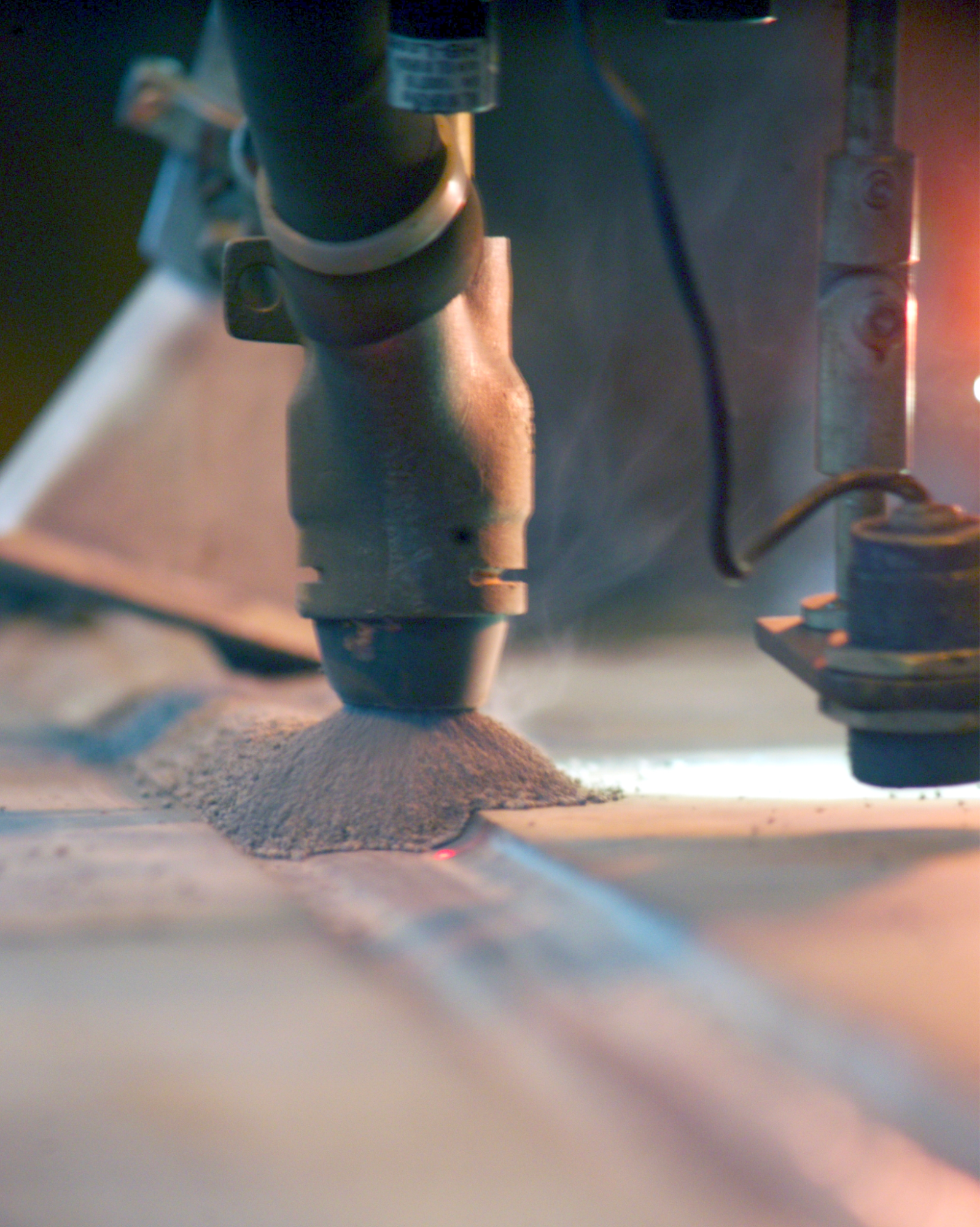
Figure 20.19 below shows a submerged arc weld being performed on a very large weldment for underwater wind turbine foundations shown in Figure 20.21. Notice the granular flux that is used which protects the weld. This flux is typically low hydrogen and must be kept in an oven at about 150 °F to up to 550 °F. As with the name, the arc is submerged and you cannot see it. SAW is a neat process to use that you should try out if given the opportunity.
The flux in Figure 20.17 above is covering the hot weld bead. Sometimes this flux will be recycled. Note that the welding does not emit fumes or smoke through the flux. SAW is used primarily on thick materials and can be used to make I-Beams and pipes.
This section discussed the uses of carbon steel and the different welding processes used to weld it. The most important thing to note is how important it is to learn more than one welding process because you may have to use multiple processes at a time during your career. Welding pipe with a GTAW root followed by SMAW interpass and cover passes is a great example.
Figure 20.10: Handheld XRF spectrometer by U.S. Department of Transportation, Federal Highway Administration in the Public Domain; United States government work
Figure 20.12: Field-assembled building by U.S. Department of Labor, Occupational Safety and Health Administration in the Public Domain; United States government work
Figure 20.13: Shipbuilding and Ship Repair by U.S. Environmental Protection Agency in the Public Domain; United States government work
Figure 20.15: Airflow Deflector Side Guard by U.S. Department of Transportation, Federal Highway Administration in the Public Domain; United States government work
Figure 20.17: A pipeline being lowered into the trench by U.S. Department of Transportation, Pipeline and Hazardous Materials Safety Administration in the Public Domain; United States government work
Figure 20.18: Erwin Water Storage Tank Replacement by U.S. Environmental Protection Agency, Office of Ground Water and Drinking Water in the Public Domain; United States government work


