26 Welding Power
David Ridge
Components of Electricity
Disclaimer: The purpose of this section is to teach you about electricity only inasmuch as it applies to welding. The subject of electricity and all the ways we use it is a much broader topic and not the focus of this chapter. Every effort will be made to keep the discussion narrowly focused on how electricity is used to weld.
To start, all matter is made up of atoms. Atoms have three main parts: protons, neutrons, and electrons. The protons and neutrons of an atom are clustered together in a little ball at the center of the atom called the nucleus. The electrons of an atom circle the nucleus in tiny orbits. Any given material is determined by the number of protons, neutrons, and electrons in the atoms that it’s composed of.
Each of the three parts of an atom has a different electrical charge. Protons have a positive electrical charge, neutrons have no electrical charge, and electrons have a negative electrical charge. If an atom has more protons than electrons, then the overall electrical charge of the atom is positive, and vice versa.
The atoms in certain materials have weak bonds with their electrons, which allows the electrons to travel to and from the other atoms in the material. These materials are called conductors, and the more readily a conductor allows the movement of electrons between atoms, the better of a conductor it is. This is important because electricity, also called an electric current, can be described as the movement, or flow, of electrons from one atom to another in a conductor.

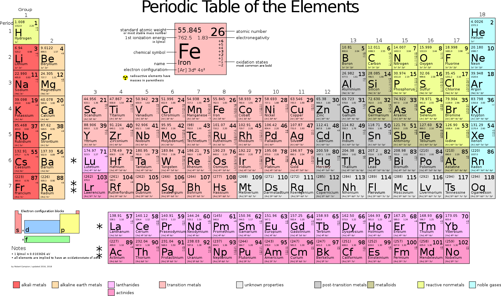
Some common conductors include iron (atomic symbol Fe) and copper (atomic symbol Cu).
There are some materials,e called insulators, that resist the flow of electricity, meaning that they do not allow electricity to flow through them very well, or even at all in some cases. Insulators are just as important to how we use electricity as conductors, and you will often find conductors and insulators used together. For example, a power cable is a copper conductor wrapped in a rubber insulator for safety. This keeps anyone from coming in contact with a dangerous electric current.
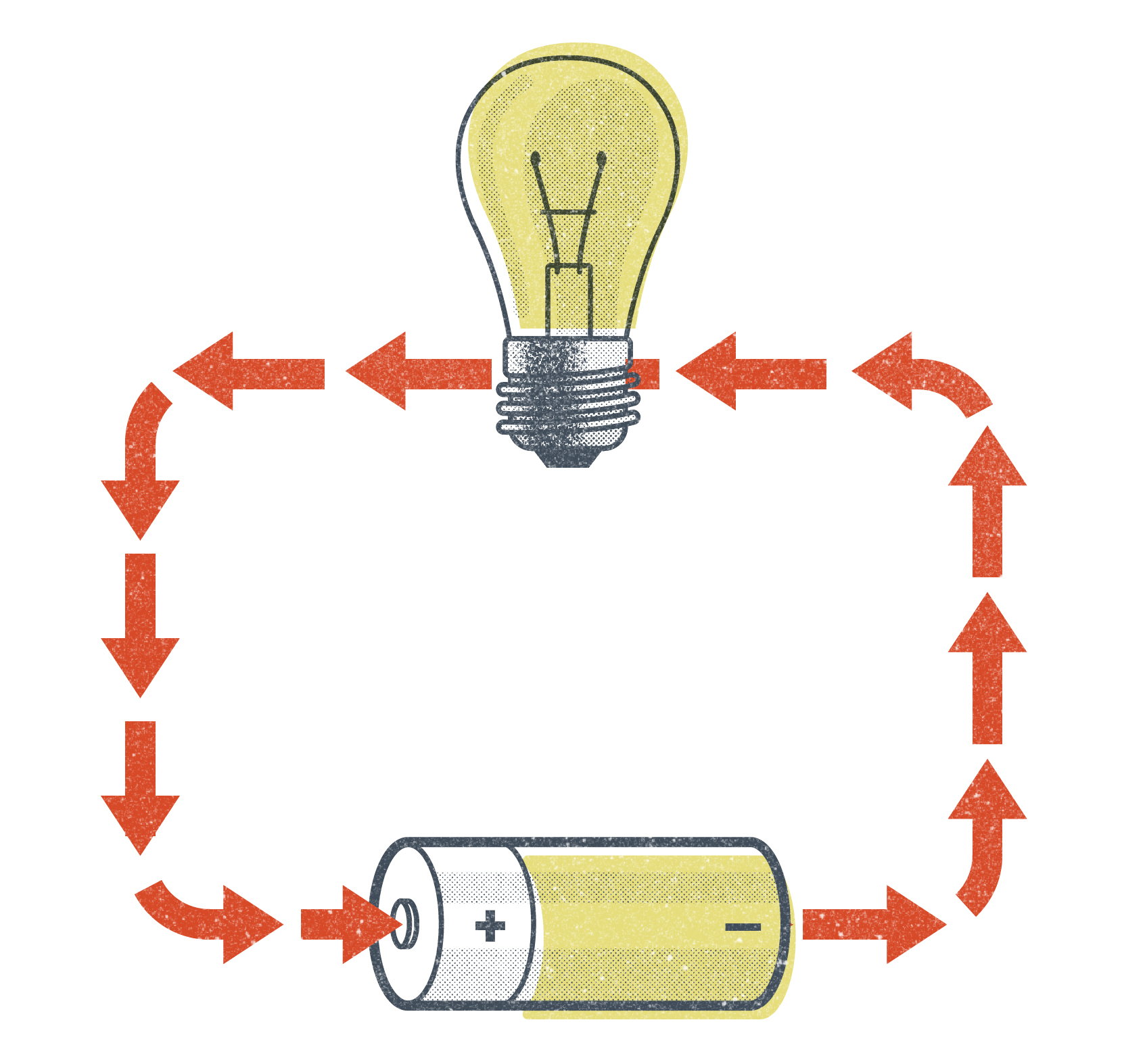
When talking about the flow of electricity, we say that an electric current flows in a circuit. This means that the electrons are flowing in a cyclical path. In fact, without a complete circuit to follow, electrons won’t flow at all. When electricity is flowing in a completed circuit, we say that the circuit is “closed.” When there is a break in the circuit (and electricity isn’t flowing), we say that the circuit is “open.”
There are a number of terms that describe and measure the flow of electricity. The most common for welders to use and hear are voltage, amperage, wattage, and ohms. Of these terms, voltage, and amperage will be the most important for you to understand as a welder because welding machine settings are based on these.
Volts/Voltage
A volt is a measure of electrical “pressure.” If we think about electricity flowing in a conductor like water flows in a hose, voltage can be compared to the water pressure. In a similar way to how the amount of water pressure determines how much force the water is pushed through a hose, voltage determines the amount of electromotive force that moves the electrons through a conductor.
In terms of welding, voltage is important for two primary reasons. First, voltage determines the actual temperature of the arc and, thereby, the weld pool. This, in turn, determines how fluid the weld puddle is. Voltage and amperage must be balanced when making a weld. So if you need your weld to be more fluid and spread out easier, you either need more voltage or less amperage.

The second reason voltage is important in welding is that voltage is needed to initiate and maintain the arc. In the case of SMAW and GTAW, there is no voltage setting on your welding machine; instead, as the welder, you control the voltage by physically manipulating the arc length. This is because these processes run on what is called constant current welding power. The longer the arc, the more voltage the welding machine will output to maintain it. Conversely, if you need less voltage, you can hold a shorter arc length to reduce the amount of voltage. In the case of the wire-feed welding processes, there is a control setting for your voltage on the machine. The machine automatically controls the voltage during welding to maintain a consistent arc length. If you need a longer or shorter arc length, you would adjust the voltage up or down on the welder. These processes use constant voltage welding power. The different types of welding power and ways of adjusting voltage are discussed in more depth later in this chapter and in the respective welding process chapters.
Open-circuit Voltage
When using processes like SMAW and scratch-start GTAW, you may notice the voltage display on your welding machine hovering at or around 80V. This voltage reading is what is called open-circuit voltage, as this is the voltage in the system when the welding circuit is open and electricity is not flowing. Processes like SMAW and GTAW use constant current welding power (discussed in more detail later in this chapter), and it takes a significant amount of voltage to initiate the arc. Once the arc is initiated though, the voltage drops down to a lower output called the welding voltage or operating voltage, which is usually between 20V and 40V as determined by how the welder maintains the arc length.
The setting of 80V for the open-circuit voltage was developed as a sort of safety mechanism. It provides enough voltage to initiate the arc but not enough to cause serious harm to a person if they came in contact with a live part of the welding circuit. Anything below 80V is not enough for the electrical current to penetrate the outer layer of skin, though it still wouldn’t feel good.
Remember that large amounts of electricity are used when welding and that the danger of electrical shock is always present. The electrodes for SMAW and scratch-start GTAW are always electrically “hot” when attached to the machine and the power is on. Always be aware of your surroundings, and don’t put yourself in a position where you could become part of a live electrical circuit. One safety tip is to always wear gloves when handling electrical components.
Amps/Amperage
An amp (or ampere) is a measure of the number of electrons flowing in a circuit. In a way, you could say that amperage is a measure of the “volume” of an electric current in a system or how much of a current there is. Going back to our example of water in a hose, the amperage in a circuit can be compared to the volume of water flowing in the hose.
Amperage is important to welding because it determines the amount of heat energy is being applied to the weld. Heat is different from temperature in that temperature is a measure of how hot or cold something is while heat is a measure of the amount of energy something has. For example, a match and a bonfire burn at the same temperature, but the bonfire has significantly more heat energy.
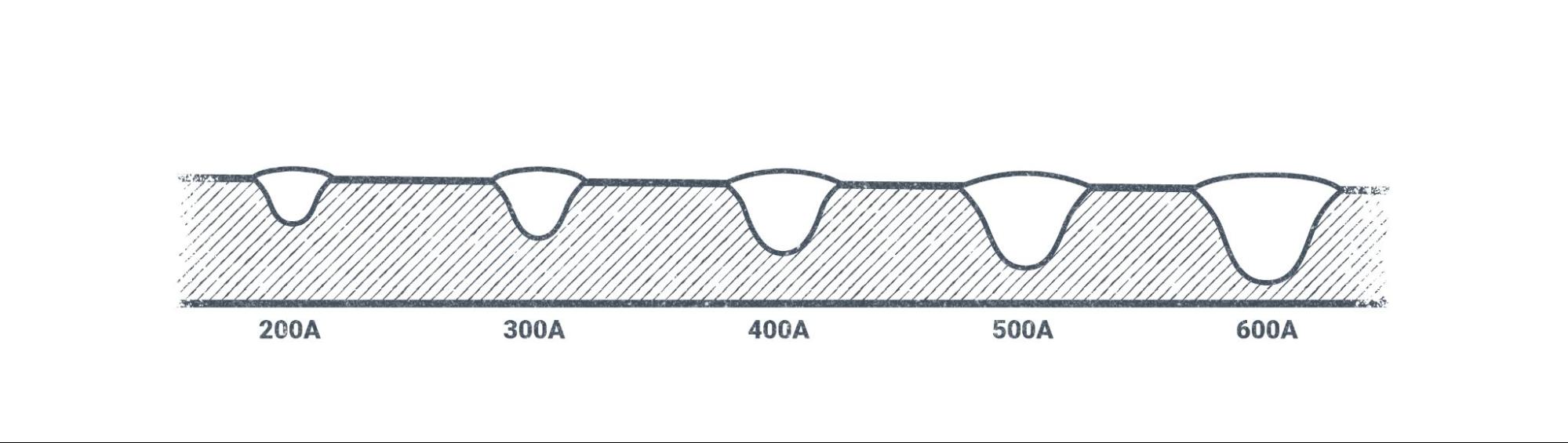
This concept is important for welding because the more heat energy applied to a weld, the better the weld penetration into the base metal. In general, the amount of amperage being used to make a weld correlates to the amount of weld penetration. Higher amperage means more penetration, and lower amperage means less penetration. The ability to adjust weld penetration characteristics is important for welding on metals of different types and thicknesses. For many processes that use consumable electrodes (electrodes that become part of the weld), adjusting the amperage also affects the rate at which these filler metals are deposited and, therefore, the speed at which the weld is made.
For processes like SMAW and GTAW, there is an amperage control setting on the welding machine. For the wire-feed processes, the amperage is tied to the wire-feed speed (wfs) control, which adjusts the speed at which the wire is fed through the system.
Watts/Wattage
A watt is a measure of electrical power and wattage is a measure of the overall power in an electric current. Because wattage is the total amount of electrical power, it is a combination of both voltage and amperage. We find wattage using a simple mathematical formula:
Volts × Amps = Watts
Wattage is not an electrical measurement that needs to be considered very often in welding. The main concern with wattage for welders is making sure the power source that the welding machine is plugged into is adequate, and even then this is usually accomplished by measuring the volts and the amps.
That being said, the same mathematical formula is useful for finding both voltage and amperage:
Watts ÷ Amps = Volts
and
Watts ÷ Volts = Amps
Algebra in the Shop
Often these equations are written using just the first letter of each word.
Volts × Amps = Watts can be written V × A = W
Watts ÷ Amps = Volts can be written W ÷ A = V
Watts ÷ Volts = Amps can be written W ÷ V = A
Ohms
An ohm is the unit of measure for resistance to the flow of electricity. When the electrons in a conductor travel from one atom to another, sometimes they bump into each other or into the atoms themselves. This is called resistance. As a welder you need not be concerned with measuring the resistance in ohms, but you need to understand the principle of resistance in an electrical system.
Resistance in a circuit creates heat. In most cases, welders want the resistance in a circuit to be as low as possible. We want the electricity in our welding leads to flow as efficiently as possible because resistance in them or at other points in the system creates heat, which causes components to degrade and break down.
However, there is one point in a welding system where resistance is crucially important, and it’s at the point of the welding arc because without this principle of resistance, arc welding would not work at all. The atmosphere we live in is not a good conductor. As the electric current is forced to travel through the atmosphere at the point of the welding arc, it encounters a lot of resistance. So much so that the heat created by the resistance can reach anywhere from 6,000 degrees Fahrenheit to 11,000 degrees Fahrenheit. The temperatures and heat energy created are what allow us to melt metals for welding.
Resistance and Safety
Sometimes certain components of a welding system become worn or damaged. Damaged components often lead to increased resistance in the system. Usually this happens with the connection points of welding leads or with work clamps or electrode holders. In certain cases the resistance caused by loose connections or wear or damage to these parts can lead to a buildup of heat that can be dangerous. Before grabbing them, always carefully check connection points, work clamps, and electrode holders to see if they are hot after welding. This can be done by placing a hand near the part, but without touching it, to sense whether it is hot.
Damaged components that frequently heat up due to resistance should be replaced. Not only will this help keep you safe, it will aid the welding machine in running well. Extra resistance in the system can have adverse effects on the quality of welds.
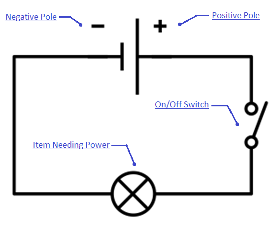
Polarity
In the context of welding, polarity is the direction the electric current is flowing through the welding system. Remember our discussion about an electrical circuit from earlier: A welding system is a big circuit in which the electricity travels from the power source through the leads and electrode, then through the base metal, and back again. You can think of a welding machine as having two poles like a magnet. There is a positive pole and a negative pole.
Welding machines output electricity in one of two ways, either as direct current or as alternating current. Some machines can only produce direct current, others can produce only alternating current, and some can produce both.
By changing which outlet our welding leads are connected to, we can change the way electricity flows through the system. In some cases, this can also be done with a switch or by changing a setting on the machine.
Direct Current
Direct current (DC) means that the flow of electricity is in one direction, all the time. This is very beneficial for the majority of welding that needs to be done, as most metals are welded using direct current. However, which direction the current is flowing has a big effect on the weld.
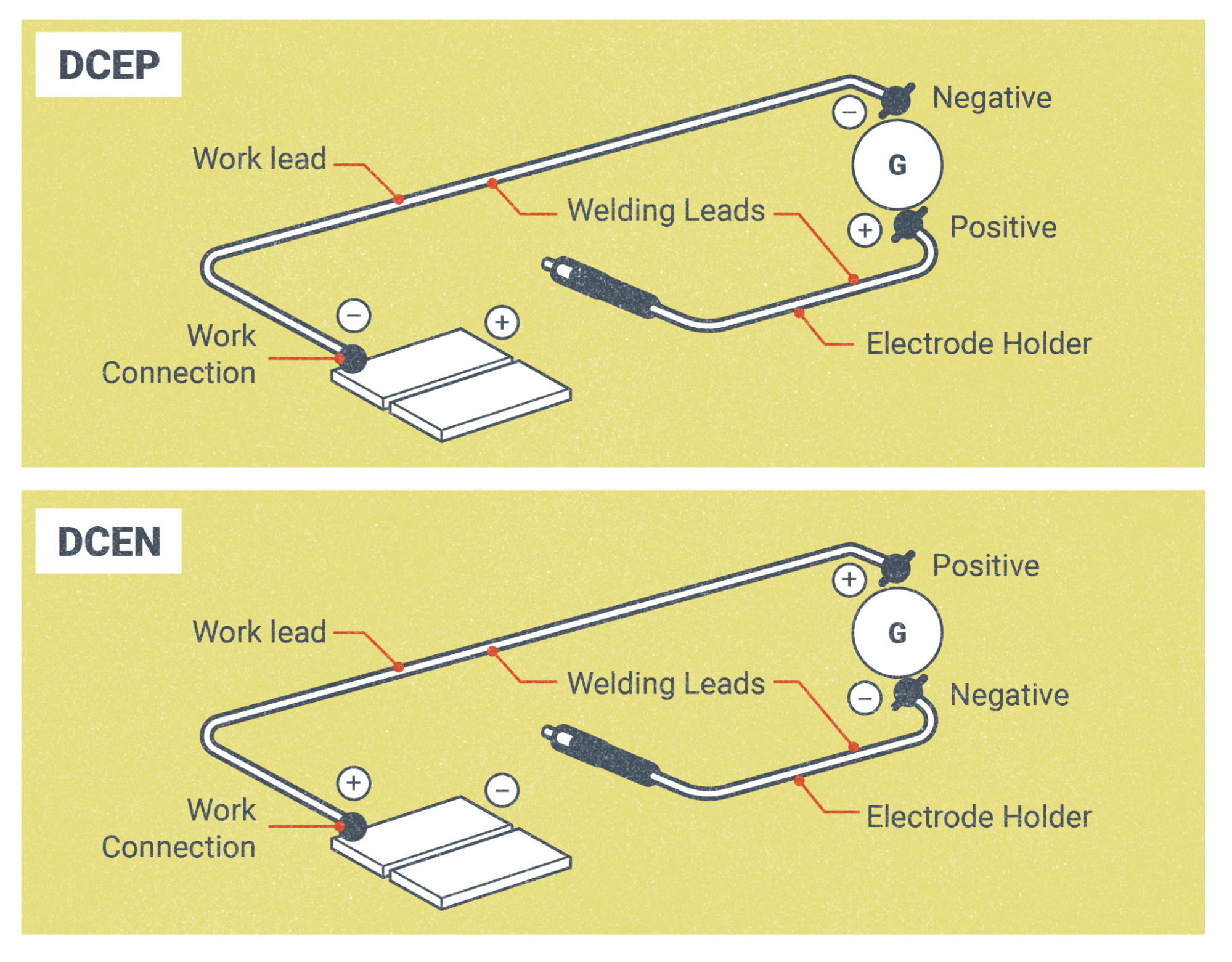
As stated earlier, we can think of a welding machine as having two poles, a positive and a negative pole. By changing which pole our workpiece lead and electrode lead are connected to, we can change the direction of the flow of electricity. This gives us two variations of direct current. We refer to them as direct current electrode positive (DCEP) and direct current electrode negative (DCEN).
DCEP means that the electrode lead is hooked up to the positive terminal on the welder and the workpiece lead is hooked up to the negative terminal. The majority of DC welding is done on DCEP. Processes like SMAW and FCAW use DCEP for most of their electrodes, and GMAW always runs on DCEP.
With DCEN, the welding leads are hooked up the opposite way, with the electrode lead being connected to the negative terminal and the workpiece lead being connected to the positive terminal. You will most likely encounter DCEN welding with GTAW and with certain self-shielded FCAW electrodes.
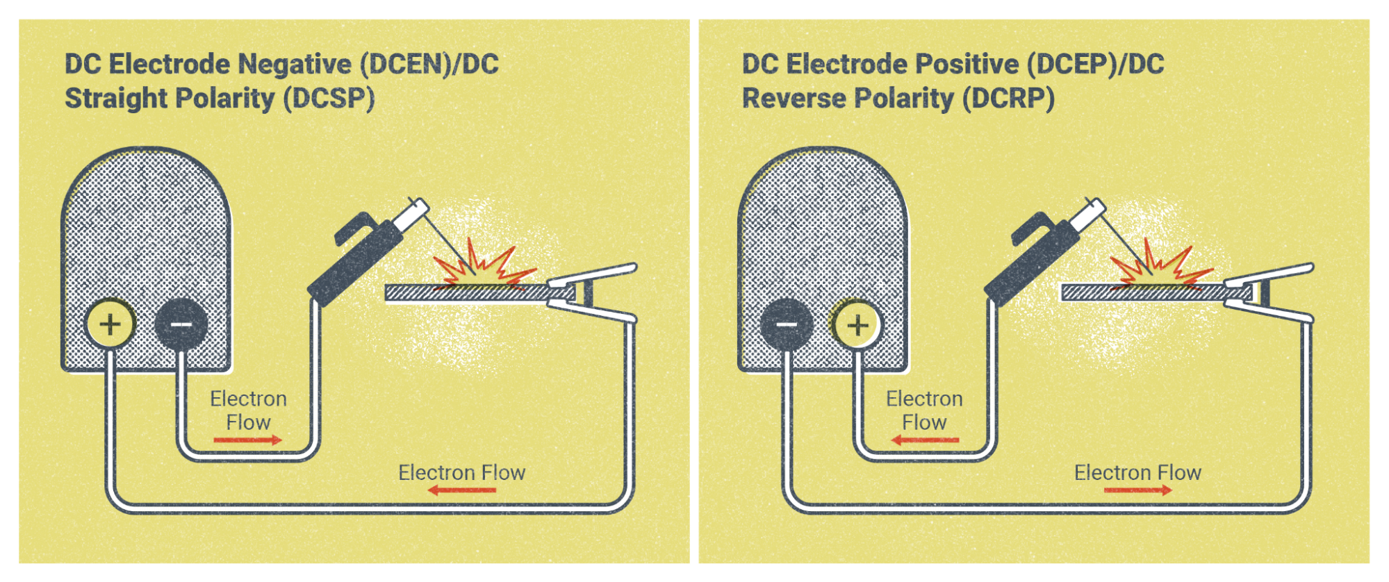
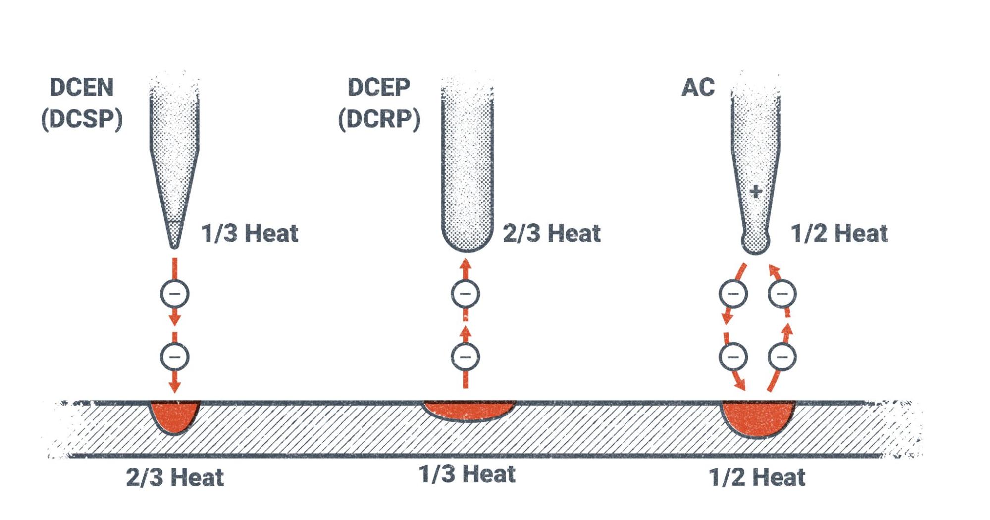
Direct Current Heat Distribution
The main reason for using one polarity or the other between DCEP and DCEN is the heat distribution characteristics of each. In a welding system, electricity always flows from the negative pole to the positive pole. So at the point where the arc is created, the negative pole is emitting electrons across the arc and the positive pole is collecting them. As the heat is created by the arc, only one-third of it is concentrated on the negative pole while two-thirds of the heat is concentrated on the positive pole.
For example, with DCEP the electricity is actually flowing from the work lead to the base metal and then jumping across the arc to the electrode and then continuing back through the electrode lead to complete the circuit. This puts two-thirds of the heat on the electrode and one-third of the heat on the base metal. This is desirable for SMAW, GMAW, and FCAW processes because they have consumable electrodes, meaning that the electrode is melted and becomes part of the weld. We need the majority of the heat on the electrode because we actually need it to melt faster than the base metal during welding.
On the other hand, with a process like GTAW there are non-consumable tungsten electrodes. We don’t want this electrode to melt and become part of the weld, so we use DCEN. Since the electrode is connected to the negative pole, only one-third of the heat is directed to the electrode with the other two-thirds is going to the base metal.
Old Terms vs New Terms
As a note, you may still hear DCEP referred to by its older name, direct current reverse polarity (DCRP) and, likewise, DCEN as direct current straight polarity (DCSP). The former terms for these polarities had to do with the direction the electricity was flowing. Since the electricity was actually flowing from the work to the electrode with DCEP, it was referred to as “reverse polarity.” DCEN was “straight polarity” since the electricity was flowing from the electrode to the work. If you’re on a job where people keep using their former names, an easy way to remember which is which is that DCEN and DCSP (which are the same thing) are represented by the minus sign (-), which is a straight line and therefore refers to straight polarity.
Alternating Current
Alternating current (AC) is an electric current that is constantly changing polarity. This is the type of electric current that you have in your house, and most electronics plug into outlets that run on AC.
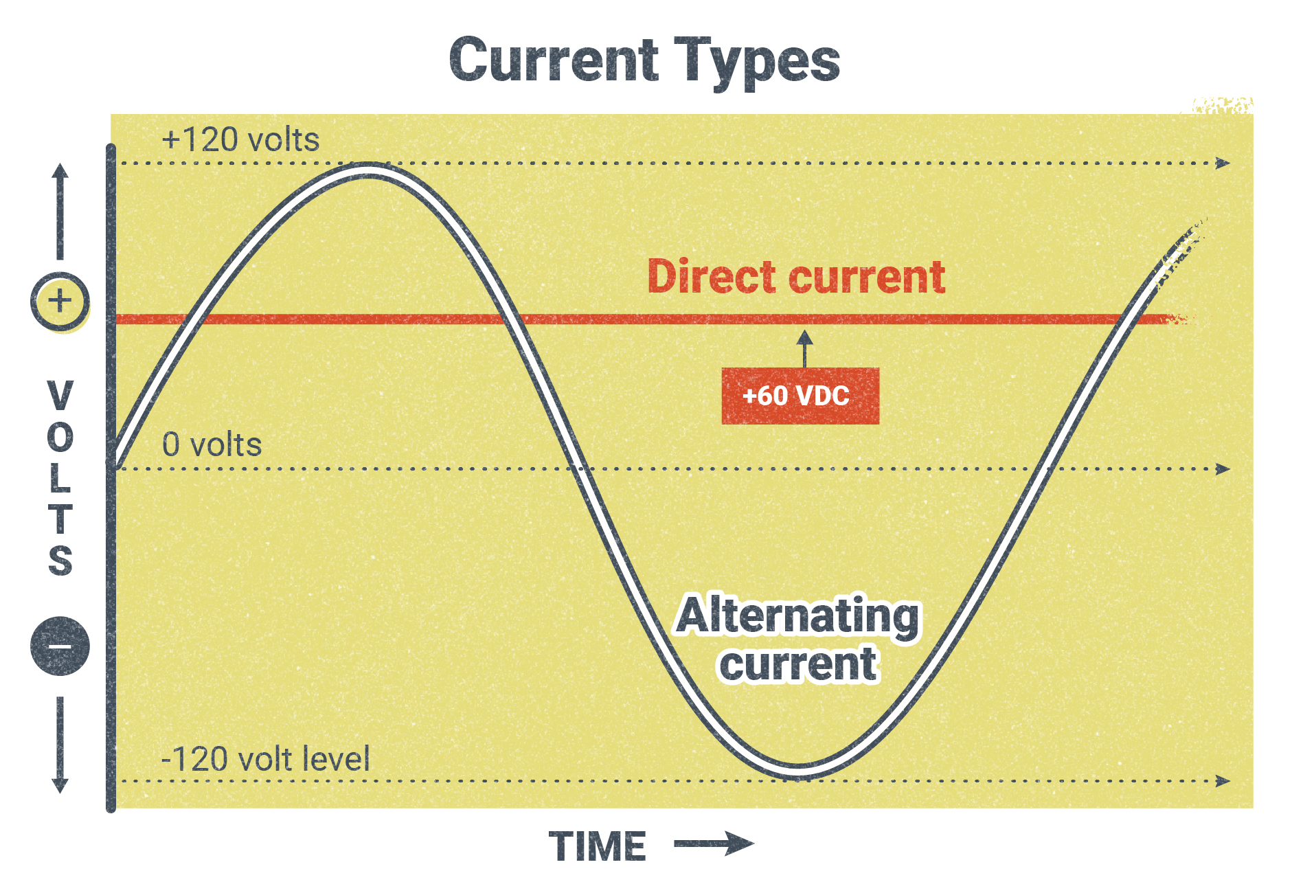
Figure 5.12 is a visual representation of AC. Above the 0V line is positive polarity and below it is negative polarity. The x-axis represents time. Notice how the AC changes from positive to negative over time. AC makes this change many times per second. The time it takes for one whole cycle is measured as a unit called a hertz. In North America, the electricity that goes to your house runs at 60 Hz, or 60 cycles per second.
What this would look like in welding is that the current flowing through the welding leads would be changing direction 120 times per second, to make 60 cycles per second.
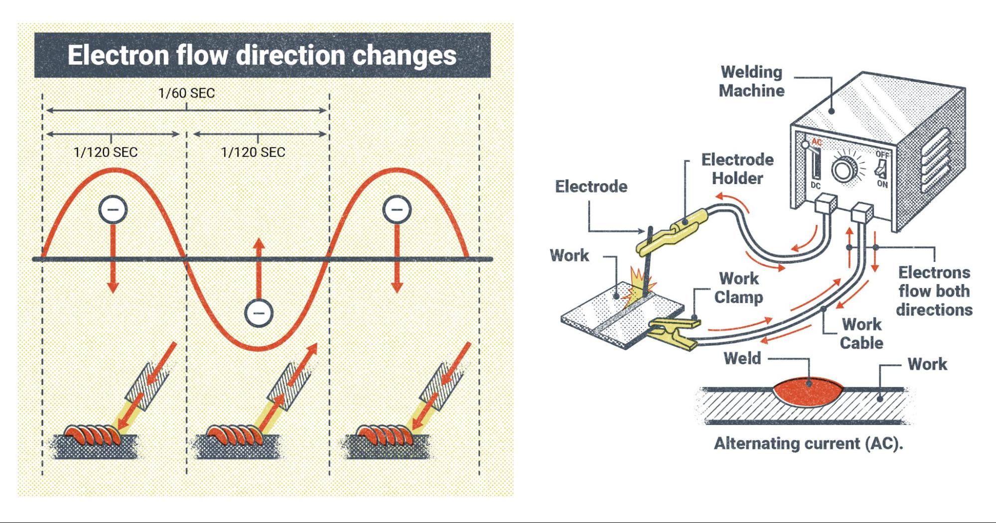
There are several reasons why welders might choose to use AC. It gives a heat distribution that is about 50/50 on the work and the electrode. The weld penetration to weld buildup ratio is also about 50/50. AC is easier to produce than DC, so machines that use AC only tend to be cheaper. With processes like GTAW welding, some metals can only be welded using AC, and with SMAW some welding rods are only designed to run on AC. It also helps eliminate the welding phenomenon called “arc blow,” which causes the arc to wander off course and can cause weld defects.
Some modern welding machines can change the number of hertz that AC cycles at, from as low as 20 Hz to over 200 Hz. Also, many machines that can produce AC can change the wave pattern, from the sine wave shown in Figure 5.12 to what is called square wave, which is much more efficient for welding (other waveforms are discussed in Chapter 11).
Types of Welding Power
There are two types of welding power (which is not to be confused with polarity). : constant current (CC) and constant voltage (CV). It is important to remember the difference, as they are used for different welding processes.
Before we review CC and CV, let’s cover some of the different welding processes.
Welding Processes
Up to now, this textbook has only mentioned the welding processes when referring to certain welding variables that are related to them. Before going any further, it will be helpful to have a basic understanding of the four main processes and how they work. Each of these processes has its own chapter that gives an in-depth explanation of its components and theory of operation. What follows is simply a brief overview to serve as a frame of reference.
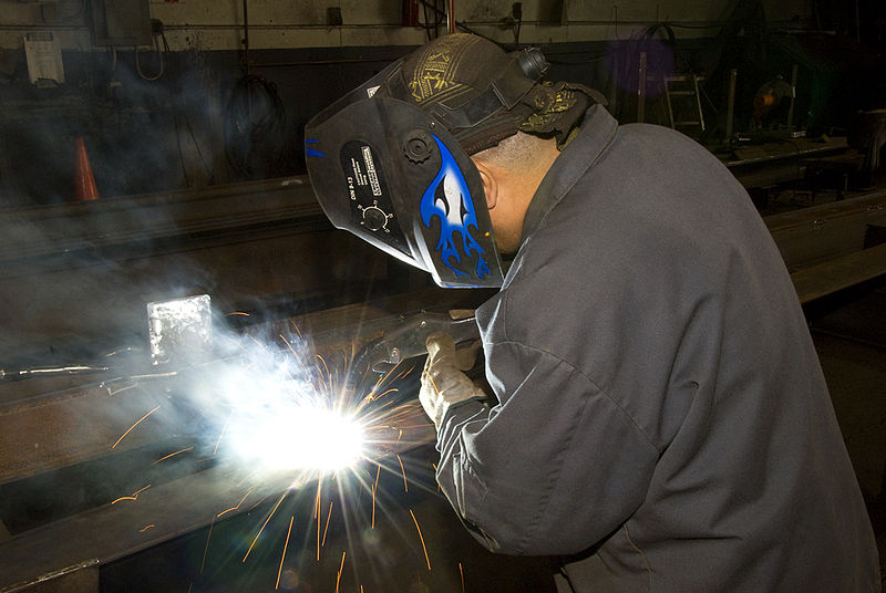
SMAW
Shielded metal arc welding (SMAW), also called stick welding, is the simplest welding process in terms of equipment and theory, and is usually the first welding process taught in schools and apprenticeships. The main components of the system are a welding power source, welding leads (cables that transfer the electricity to the weld), a work clamp and an electrode holder, and coated metal electrodes to make the weld.
The welding power source sends power through the work lead, which is attached to the base metal with the work clamp, and an electrode lead attached to the electrode holder. The electrode holder grips the coated metal electrode, which is a metal rod covered in a mineral substance called flux. The arc is struck between the rod and the base metal and as the weld progresses the metal rod is melted to become part of the weld and the flux is burned and consumed. Parts of the flux melt and coat the newly formed weld in a material called slag. Other elements burn off, creating a shielding gas cloud that surrounds the weld zone during welding. Both the slag and the shielding gas are intended to protect the weld from the atmosphere, because molten metal reacts badly with elements in the normal atmosphere.
SMAW is known for its simplicity and its ability to weld almost any metal, if the right type of welding rod is used. However, it does require a slightly higher level of manual skill than some other welding processes, such as GMAW welding.
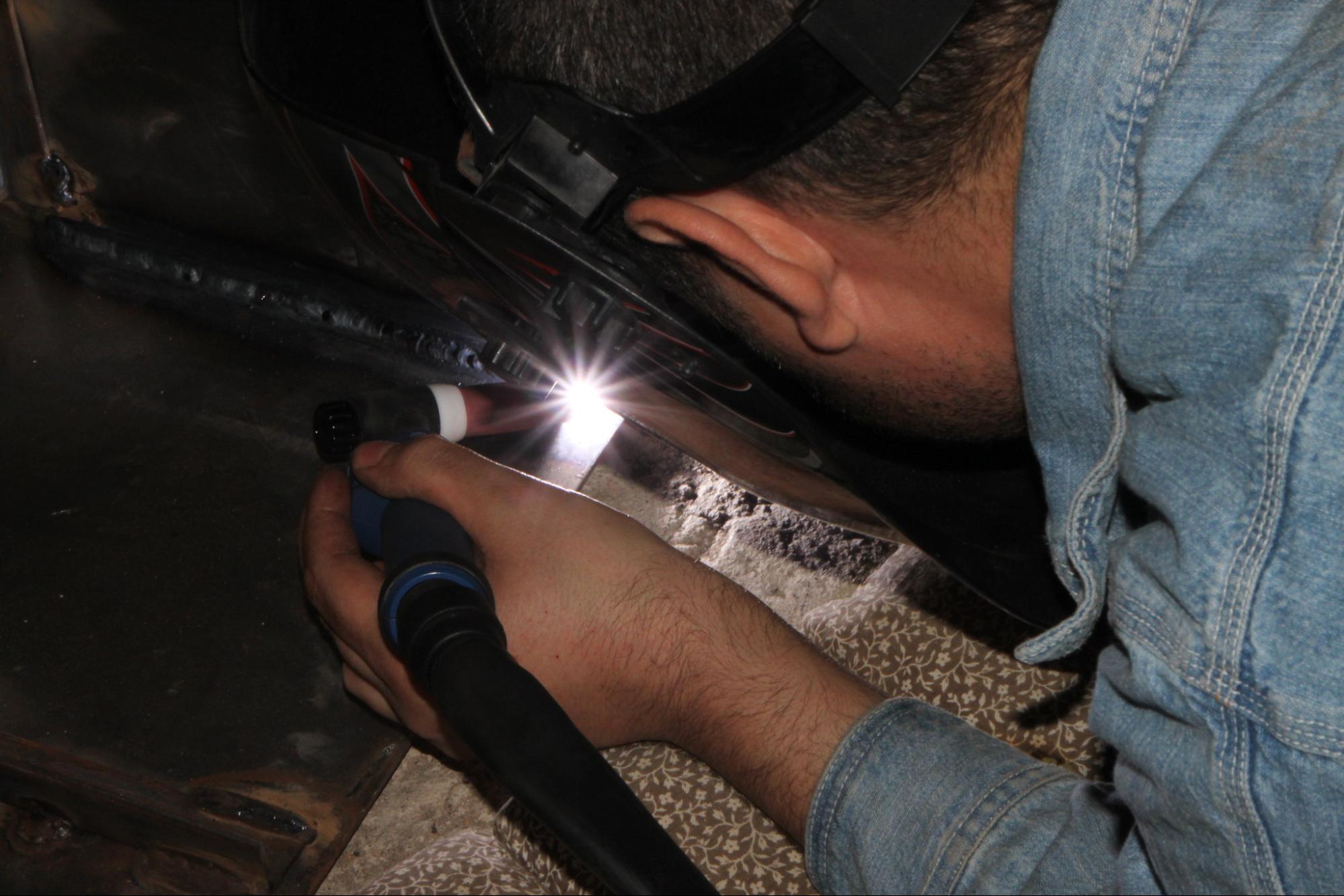
GTAW
Gas tungsten arc welding (GTAW) was originally known as tungsten inert gas (TIG) welding, and many welders still refer to it as TIG welding today. The electrode lead for GTAW welding is more than just a power cable. Rather than a simple electrode holder, GTAW uses a welding torch that allows for shielding gas and sometimes cooling water to pass through, as well as the welding current. The torch holds a tungsten electrode, from which the arc is emitted. This electrode is not consumed, as with SMAW, but only serves to conduct the electricity for the arc. A secondary filler metal, in the form of a bare metal rod, is added by hand to the weld pool as the arc travels along the base metal. Instead of having flux to create slag or shielding gas, a separate bottled shielding gas is used. This shielding gas is usually an inert gas, such as argon or helium, and is passed through the torch to the weld zone.
GTAW welding setups can be very simple, however modern GTAW welding power sources tend to be the most complicated when it comes to the welding settings. Additionally, the majority of GTAW welding machines nowadays use a foot pedal or thumb control to adjust amperage in real time during welding. Similarly, in many cases a water cooler or water chiller unit is added to help keep the welding torch cool, as it can easily overheat because of the slow welding speed of this process. Despite its slowness, GTAW welding is very desirable for its precision and cleanliness, as well as its ability to weld a wide variety of metals.
Helium: A Nonrenewable Resource
As a note on the gas used in GTAW, helium is a gas found in the earth’s crust. Its atoms are so small that they can pass between the atoms of any man-made container designed to hold it, thus allowing it to leak out. This is why your helium balloon goes flat after a few days. This property also allows for this gas to escape the gravitational pull of the earth and leave our atmosphere. This and our inability to artificially create helium means it is considered to be a nonrenewable resource. Although there is thought to be enough helium reserves for a number of years to come, helium usage is starting to be regulated and restricted (Helium, n.d.).
GMAW
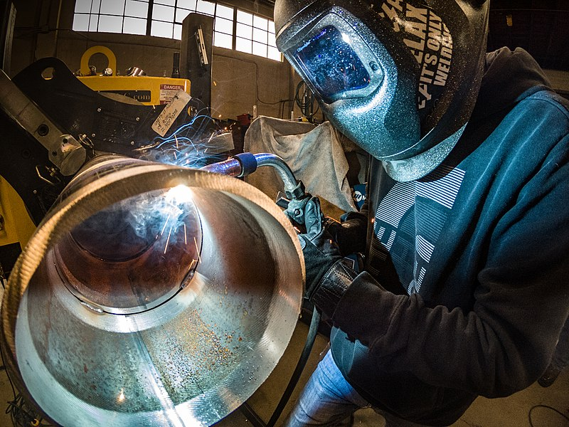
Gas metal arc welding (GMAW) was at one time called metal inert gas (MIG) welding and most welders still refer to it this way today. You may also hear it called hard wire welding due to the solid metal wire electrode used in its wire-feed process. A bare wire electrode is fed from a spool through a welding gun into the weld. Some GMAW welding power sources have a built in wire-feeder unit, but in many cases the feeder unit is a separate component that must be attached to the power source. As the wire electrode is fed out of the gun, it is continually melted and becomes part of the weld. A bottled, external shielding gas is also fed through the gun to protect the weld so, like GTAW welding, there is no slag. The gas is usually carbon dioxide, or a mixture of argon and carbon dioxide.
Wire-feed processes like GMAW are more complicated in terms of the equipment required, but they are easier for new welders to learn. These processes also have the advantage of being able to make long welds quickly due to the spooled wire electrode. This is in contrast to SMAW and GTAW, which are much slower and the length of weld deposited at one time is limited by the length of the welding rod. The main drawback of GMAW welding is that there are a limited number of materials that can be welded with it, often because of the thickness of the material. Generally, GMAW is limited to thin materials like steel and aluminum. In the case of short-circuit gas metal arc welding (GMAW-S, also called short-circuit MIG or short-arc welding), it is not recommended for use on materials over one-quarter inch in thickness.
FCAW
Flux-cored arc welding (FCAW) is a wire-feed process similar to GMAW. In fact the same equipment used for GMAW can also be used for FCAW by changing a few parts in the welding gun and the wire feeder unit. The primary difference between the two processes is in the wire electrode. FCAW uses a tubular wire electrode that is filled with flux. Much like SMAW, the flux burns and creates slag and shielding gas to protect the weld.
There are two types of FCAW. One uses a bottled shielding gas in addition to the shielding from the flux. This is gas-shielded flux-cored arc welding (FCAW-G), which is also called dual-shield welding. The other type is called self-shielded flux-cored arc welding (FCAW-S), or inner-shield welding, and all protection for the weld comes from the flux alone. While FCAW is limited to welding ferrous metals (like steel, stainless steel, or cast iron), it is known for its speed and strength. Unlike GMAW, which is often limited to welding thinner materials, FCAW is able to weld materials of any thickness.
Constant Current
Now let’s return to the two types of welding power. CC is used for welding with SMAW and GTAW/TIG. They are both manual processes, meaning the welder controls almost everything by hand. As you recall from earlier in the chapter, both processes use their arc length to control the voltage applied to the arc. Lengthening the arc raises the voltage and shortening the arc lowers it.
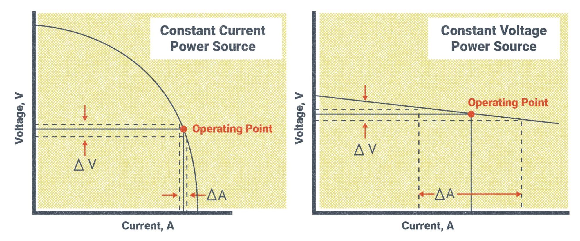
CC power gets its name from the fact that the welding machine always tries to maintain a constant wattage output. Remember that wattage is the total amount of electrical power and is composed of the total voltage and amperage. Looking back to our formula from earlier, we know that V × A = W. If the machine tries to keep a steady wattage output, this means that changes in voltage as a result of changing the arc length will also change the amperage. If the voltage increases the amperage will decrease, and vice versa, but the overall wattage will remain the same.
To illustrate this, say you set the amperage on the machine to 80A and then maintain an arc length that requires 24V. Using the formula V × A = W, we know that 24V × 80A = 1,920W. At that amperage setting, the welding machine will always try to maintain that 1,920W output. If the voltage were to increase to 30V, due to increasing the arc length, the amperage would automatically decrease to 64A, because 30V × 64A = 1,920W. Conversely, let’s say the voltage decreased to 20V due to holding a tighter arc length. We know that the amperage will instead increase to 96A, because 20V × 96A = 1,920W.
Hopefully these examples give you an idea of what is taking place. They are not a completely accurate representation of the actual numbers because we do not want large fluctuations in amperage while welding. So in reality the total wattage will change a little. Figure 5.18 shows CC power on a graph, with the curved line representing the total wattage. You can see how changes in voltage affect changes in amperage.
Constant Voltage
CV power is used for all wire-feed welding processes. This includes GMAW/MIG and FCAW. These are known as semi-automatic processes. This means that the welder controls everything by hand, except for the feeding of the wire electrode, which is fed automatically by a wire-feed unit.
With these wire-feed processes, the main controls that welders can adjust on the welding machine are voltage and WFS. There is no amperage control; rather, the welding machine automatically adjusts the amperage to what is needed in order to fully melt the electrode as it is fed into the weld pool. So as you turn the WFS up, the welder automatically increases the amperage to melt the wire faster.
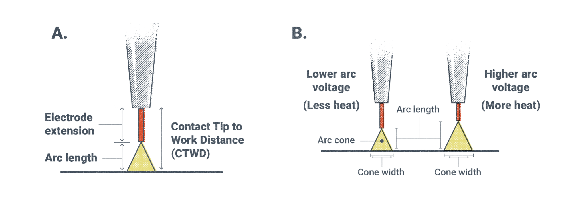
CV power gets its name from the fact that the welding machine tries to maintain a constant voltage setting throughout the weld. Because the wire is fed automatically, the welder is no longer able to maintain the arc length by hand. Instead, the machine maintains a constant arc length by maintaining one voltage. So, in a sense, when you set your voltage on the machine, you are actually setting the arc length. More voltage means a longer arc and less voltage means a shorter one. Along with the change in arc length, there is a change in how wide the cone of the arc is at the weld pool.

Because the welder still controls the movement of the welding gun/torch by hand, there will no doubt be fluctuations in how far or close they hold the gun/torch to the weld pool. Even an experienced welder cannot help this. CV power is able to accommodate this by maintaining a constant voltage and arc length and automatically adjusting the amperage. The closer the welding gun is held to the weld pool, the more amperage is required to melt the wire electrode. Figure 5.20 gives a visual representation of what is happening with the voltage and amperage when using CV power.
It should be noted that although it is said that the machine maintains a constant voltage, this is not entirely accurate, as there are always small variations. This is because no set of welding circumstances or machines are ever truly perfect.

Also, it is important to remember that voltage and WFS need to be balanced with each other in order to make good welds. Each wire electrode has a set of suggested settings that help welders determine how to adjust their welding machines.
Attributions
- Figure 5.1: Atom Diagram by AG Caesar is released under CC BY-SA 4.0
- Figure 5.2: Periodic table large by DePiep is released under CC BY 3.0
- Figure 5.3: Simple-electric-circuit by MikeRun is released under CC BY-SA 4.0
- Figure 5.4: Effect of Arc Voltage On Bead Shape by Nicholas Malara, for WA Open ProfTech, © SBCTC, CC BY 4.0
- Figure 5.5: Effects Of Voltage On Arc Length by Nicholas Malara, for WA Open ProfTech, © SBCTC, CC BY 4.0
- Figure 5.6: Effects Of Amperage On Penetration by Nicholas Malara, for WA Open ProfTech, © SBCTC, CC BY 4.0
- Figure 5.7: Different Direct Current Polarities by Nicholas Malara, for WA Open ProfTech, © SBCTC, CC BY 4.0
- Figure 5.8: Which Polarity? by David Ridge, for WA Open ProfTech, © SBCTC, CC BY 4.0
- Figure 5.9: How Direct Current Works by Nicholas Malara, for WA Open ProfTech, © SBCTC, CC BY 4.0
- Figure 5.10: DCEN And DCEP Welding Machine Setup by Nicholas Malara, for WA Open ProfTech, © SBCTC, CC BY 4.0
- Figure 5.11: Heat Distribution For Each Polarity by Nicholas Malara, for WA Open ProfTech, © SBCTC, CC BY 4.0
- Figure 5.12: Alternating Current Sine Wave by Nicholas Malara, for WA Open ProfTech, © SBCTC, CC BY 4.0
- Figure 5.13: AC Welding Machine Setup by Nicholas Malara, for WA Open ProfTech, © SBCTC, CC BY 4.0
- Figure 5.14: SMAW by Mgschuler is released under CC BY 3.0
- Figure 5.15: TIG-Welding-GTAW__102400 by Emilian Robert Vicol is released under CC BY 2.0
- Figure 5.16: Migpipe by Weldscientist is released under CC BY-SA 4.0
- Figure 5.17: Welding the frames (2929458501) by Oregon Department of Transportation is released under CC BY 2.0
- Figure 5.18: Constant Current And Constant Voltage Electrical Characteristics by Nicholas Malara, for WA Open ProfTech, © SBCTC, CC BY 4.0
- Figure 5.19: Effects Of Voltage On Arc Length by Nicholas Malara, for WA Open ProfTech, © SBCTC, CC BY 4.0
- Figure 5.20: Effects Of Voltage On Arc Length by Nicholas Malara, for WA Open ProfTech, © SBCTC, CC BY 4.0
Some people are interested in welding as a career. Others simply want to do it for themselves as a hobby or maybe a side business. The path you choose in welding will largely determine the kinds of tools and equipment you encounter and the size of shops you work in. There will be differences in what equipment may be found in a home shop or garage versus an industrial fabrication shop, as well as their capabilities. A few factors contribute to those differences, and we’ll review them here.
Power Supply
Power supply constitutes a major difference between a home shop and a fabrication shop. Most residential service drops (electrical line connected to a utility pole) do not exceed 200 amps, split between all circuits connected to it. The available voltage will be 110V/120V and 220V/240V, and the number of circuits may be limited. In contrast, a decent-size fabrication shop can have a service drop of several thousand amps, with dozens of circuits and voltages up to 480V. Additionally, many circuits in large shops are wired for three-phase power, which is a three-wave version of alternating current required for some machinery such as large electric motors. These high-powered electrical circuits require large circuit breakers, such as up to 50 amps.
This difference in available power influences the size and number of machines and equipment a shop has. It is important to match the lineup of welders and other tools with the power supply. For instance, it wouldn’t make sense to buy a welder that required more power than was available at the shop.
Application
It is fairly common sense that the smaller a shop, the more limited it is in its work capacity simply due to space. Shop space is not only important for the room that is necessary to work on projects, but also for how much equipment can reasonably fit in the shop. Large fabrication shops specialize their workspace for the size and type of material they handle and the products they put out, streamlining to increase production. This is not to say that home shops or small shops can’t do lots of work, but that they must be somewhat selective in the types of things they work on. This means many home shops and other small fabrication outfits produce quality products, but usually in less quantity and size.
Another factor determining a shop's workload limit and type of work is the number of persons working at one time. For a home shop where the welder is simply working as a hobby, this isn’t a big issue. But a small business run from a garage or small workshop can be limited in how many people they can bring in to work. This greatly affects the business' time and capabilities, specifically the number of hours that can be put towards finishing a product. AAs an example, one person working a standard 40-hour week will only ever put in 40 hours of work per week. If a job is estimated to take 120 hours, it would take that person three weeks to finish it. Simply adding a second person brings the working hours to 80 per week, cutting the production time in half as far as delivering the product. This is not a perfect example, but it gives you a picture of this concept: Shops that have more workers can complete tasks faster. Additionally, it is easier to work on large weldments in a team of two or three people. However ,it is worth repeating the point that a limited number of workers does not necessarily mean lower quality of the work.
One outlier in the field of small welding operations is mobile welders, who travel around with all their equipment. Sometimes they are part of a larger organization, but often they are an individual welder in business for themselves. Mobile welding businesses are purposefully small because everything the welder needs has to fit, usually, on a single truck. Mobile welders are skilled professionals who know how to get by with the minimum amount of tools and equipment, and the value of these small operations is in their necessity. These welders service customers who have a broken piece of equipment that needs to be repaired immediately or need something built in an area where no welding shops exist or are willing to do the work. Therefore, these customers are usually willing to pay handsomely for the work to be done.
Material Handling
One aspect of welding and fabrication that often gets overlooked until it is too late is material handling. This isn’t too much of a problem for the hobbyist in their own garage, as the projects they work on will likely be small. But as a shop starts to take on larger projects, material handling can become a limiting factor.
Metals are fairly heavy, and particularly steel, with a weight of 0.283 lbs per cubic inch (7.85 grams per cubic centimeter). To put this in perspective, a one inch (2.5 cm) square bar of steel one foot (30.5 cm) long weighs just under 3.5 lbs (1.56 kg). One cubic foot of steel weighs 489 lbs (221.81 kg). Weight is not the only issue either. Space can be a challenge as well, as many steel bars, angles, channels, tubes, and pipes often come in standard lengths of 20 feet (6.1 m). Plate and sheet steel often come four feet (1.2 m) wide and anywhere from 4–20 (1.2 m to 6.1 m) long.
This is to say that, at a certain point, it is not possible to move materials yourself and material handling equipment and machinery need to be considered. Things like forklifts, hoists, and cranes are common in large shops, but a garage shop might find the expense and space requirements of these tools to be out of their reach. While there are small hoists and hand-powered fork trucks , they may not be sufficient to handle large materials if the need arises.
All material handling tools have weight limits that must be considered before moving any object. And understanding the material handling needs of any project and whether your shop can accommodate it is an important step to take before beginning the work.
Shop Safety
As with everything in the welding and fabrication industry, safety when considering tools, equipment, and the welding shop is important. Remember that working safely is always your responsibility. No amount of rules, regulations, or precautions is a substitute for common sense and being aware of your environment. Building a good safety mindset should be just as much a part of learning to weld as the welding skills themselves.
Tool safety is such a broad category that it would be difficult to list every possible hazard. However, keep the following things in mind when working with the tools covered in this chapter.
It is important to maintain any tool in good working order. If a tool or an accessory of a tool becomes damaged, it is better to take it out of service until it can be repaired or replaced.
Many hand tools can get burs or sharp edges as they are used. Wear gloves as often as possible and make sure such burs and sharp edges are filed or sanded off as they appear.
Almost all power tools and shop equipment have guards or other safety features. Never use a tool or piece of equipment without the safety features in place.
Many power tools, such as grinders and drills, have trigger locks that allow the tool to keep working without the operator needing to constantly hold the power switch on. Make sure the trigger lock is off before plugging in a tool, or else it could start up unexpectedly while being held in a hazardous manner.
Never set a power tool down or leave a piece of equipment until it has completely stopped or shut down.
All power tools and pieces of shop equipment have moving parts. While keeping any part of your body or clothing from touching these moving parts is important, it is especially important with rotating parts, such as a spindle or wheel, since they have a tendency to grab clothes and pull you in.
Keep your body parts and clothing away from power tools and equipment with clamping or shearing functions, as these will crush or cut off whatever is put in them. Don't allow any body parts to get in between these tools and the material they are clamping or shearing, as this can result in body parts being pinched and crushed.
Follow all electrical safety guidelines for working with power tools and equipment. Keep an eye out for damaged power cords and other electrical components and take any compromised equipment out of service. Be sure a machine’s power switch is off before plugging it in or unplugging it. If a high-voltage cable is damaged, turn off the breaker before handling it or unplugging it.
Take cautions when involved with material handling. Be aware of other workers moving material around you, and always alert others to your presence if you are the one moving material. Never try to lift a heavy object by yourself. If the material is too heavy to lift safely by hand, always use an appropriate machine or device. Stay out of the path of hoists, cranes, or forklifts and never put yourself or any part of your body under the material or in any pinch points between the material being moved and stationary objects. When lifting material with a crane or hoist, stay to the side of it and always keep one hand or a rope (called a tagline) on it to keep it from swinging. No matter how you are moving material, be careful not to hit any shop equipment or other objects in your path. If a piece of material falls and lands on a power cable or air line, be cautious, as severed power cables and air lines should be shut off at the source before being handled.
Compressed air in a shop can be more dangerous than most people realize and requires special precautions. Wear eye protection while usingequipment that eject air from a vent somewhere on the tool, which can kick up debris from grinding, sanding, or cutting. Compressed air can also contain moisture from the compression process. This moisture can travel through the pneumatic hoses that attach to air tools and can be blasted into electrical equipment. This is especially dangerous with plasma-cutting tools. Attach a moisture filter to the air compressor to prevent this hazard.
If an air hose is severed, it can whip around wildly if there is enough air pressure. Do not try to grab a flailing air line, as you could be struck and injured in the process. Instead, shut off the air at the compressor or manifold before picking up the hose.
Compressed air alone can be dangerous. Be very careful with air nozzles that are commonly used to blow dust and debris off parts and never put an air nozzle directly against your skin: the air can be at such a high pressure that it can penetrate your skin. This may cause an air bubble, called an embolism, to enter your bloodstream, which can work its way to your heart and cause death.
Finally, never substitute compressed oxygen for compressed air. Oxygen is one of the three elements on the fire triangle. While not a flammable gas in and of itself, it makes everything it touches flammable. If you were to use oxygen to blow debris off a part or your clothes, or somehow attach an oxygen line to a pneumatic tool, you would have just saturated everything in the area with oxygen. Then all it would take is for a small spark to ignite the oxygen-rich environment.
Working in a fabrication shop of any kind means working in a hazardous environment. However, these hazards are overcome by safe work practices. Hundreds of thousands of people in America and around the world work safely and effectively in these environments every day. They succeed by paying attention and working in a common sense manner. With training and practice, you will also.
This textbook used the following sources:
- Joiner, Matt (2021) Shielded Metal Arc Welding-Bead, Butt, Lap and T-Fillet Weld Joints. Online Course Materials.
- Pipe Welding (2024) Lake Washington Institute of Technology. Open WA.
- Rupik, Douglas et. al (n.d.) Introduction to Welding. Open WA. Pressbook.
- Wire Feed Welding (2024) Lake Washington Institute of Technology. Open WA. Pressbook.
- WLD-112 Basic Welding Processes (n.d.) OER Commons. Course Materials.
An American National Standard. (2021). Safety in Welding, Cutting, and Allied Processes. In American Welding Society (pp. 1–72). https://aws-p-001-delivery.sitecorecontenthub.cloud/api/public/content/f524cc78ee9c4e00a703bbe12b2f368b
Giles, Z. (2022, April 14). The History of Plasma Cutting: The Evolution of Plasma Cutting. American Torch Tip. https://americantorchtip.com/blog/plasma-cutting-history-the-evolution-of-plasma-cutting/
Plasma, waterjet and laser cutting systems from Hypertherm. (n.d.). Www.hypertherm.com. Retrieved May 16, 2024, from https://www.hypertherm.com/en-US/global-landing-page/?returnUrl=751
Making Cuts
Before you start, make sure you have all your PPE on. The following chart shows the recommended shade (ANSI Z49.1) you will need to protect your eyes.
|
Amperage |
Minimum Shade |
Recommended Shade |
|---|---|---|
|
Less than 20 |
4 |
4 |
|
20-40 |
5 |
5 |
|
40-60 |
6 |
6 |
|
60-80 |
8 |
8 |
|
80-300 |
8 |
8 |
|
300-400 |
9 |
12 |
Note: Table reprinted from ANSI Z49.1 (“Guide For Shade Numbers” pp. 9)
Once you are wearing the needed PPE to safely complete your cut, follow this process:
- Hold the touch perpendicular to the metal being cut.
- Pull the trigger and drag the torch across the metal.
- If you do not have a drag tip or shield you will want to hover about ⅛ inch for the material.
- Just like welding you will always want to practice on a similar piece of material before starting on your actual project. This way you can troubleshoot your settings.
- If you are not cutting all the way through you need to slow down and turn up your amperage.
If you find that you have excessive dross on the bottom of your cuts. This can be caused by going too slow. Increase your speed a little. It can also be caused by excessive travel speed so do not go too fast either. If you are not cutting all the way through your material you run the risk of the molten metal blowing back into your torch and at you.
If you are experiencing a negative kerf angle (the sharp part of the metal is at the top and drifts away at the bottom) you are too close. If you have a positive kerf angel (the part looks like it has a bevel on it) you are holding the torch too far away. If you are getting a square edge on your cut this is outstanding, keep it up.
Direction of your cut masters. This matters because of the swirl that is produced inside the torch. When cutting a part where you want to keep the inside of the cut, the travel direction should be clockwise. When cutting out the interior of a part (so you will keep the outside of the cut) you will want to travel counter clockwise. This will give you the best end product.
After you have made your cut it will be hot. You will want to be cautious when handling metal after it has been cut. Most of the dross should break off very easily with a chipping hammer.
Maintaining the System
Maintenance for a Plasma cutter is quite simple. Check all electrical connections before and after use. Replace the consumables in the torch when needed and the occasional blow down with compressed air. As always check the owner's manual for detailed instructions.
Special Safety Considerations
Safety is paramount when plasma arc cutting (PAC).
Electrical shock is a possibility. Always wear your PPE and do not operate if you are wet or have sweat through your gloves. Whenever possible, reduce the probability of being shocked. If using an extension cord concert the machine to the cord then the power and when disconnecting disconnect the power then the machine from the cord.
Fire is another hazard to be aware of. As you can see in most of the pictures there are lots of sparks. Make sure to check your surroundings before you start cutting and make sure you know where the nearest fire extinguisher is.
Compressed air is another safety concern when plasma arc cutting. It can puncture the skin and create debris that can get in your eyes. Be careful when using compressed air.
Both outside the visible light spectrum of the human eye, ultraviolet and infrared light can be hazardous and burn your eyes. Always wear the appropriate safety shade for your eyes. Please be sure to check the shade recommended by ANSI Z49.1 and presented earlier in this chapter to ensure you have proper protection for your eyes.
Machined torches and CNC machines have their own safety concerns the you will want to pay close attention to. Be sure to ask for specific safety guidelines and read the manufacturer’s warnings carefully before operating these machines.
Attributions
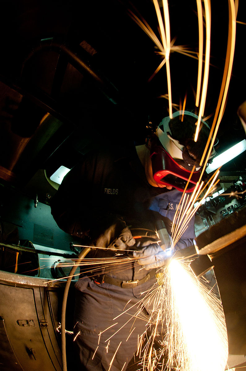
- Figure 14.15: US Navy 111128-N-OY799-092 Hull Maintenance Technician Fireman Tom Fields, from Brinnon, Wash., uses a plasma cutter in the sheet metal shop aboard by Mass Communication Specialist 3rd Class Kenneth Abbate in the Public Domain; United States government work
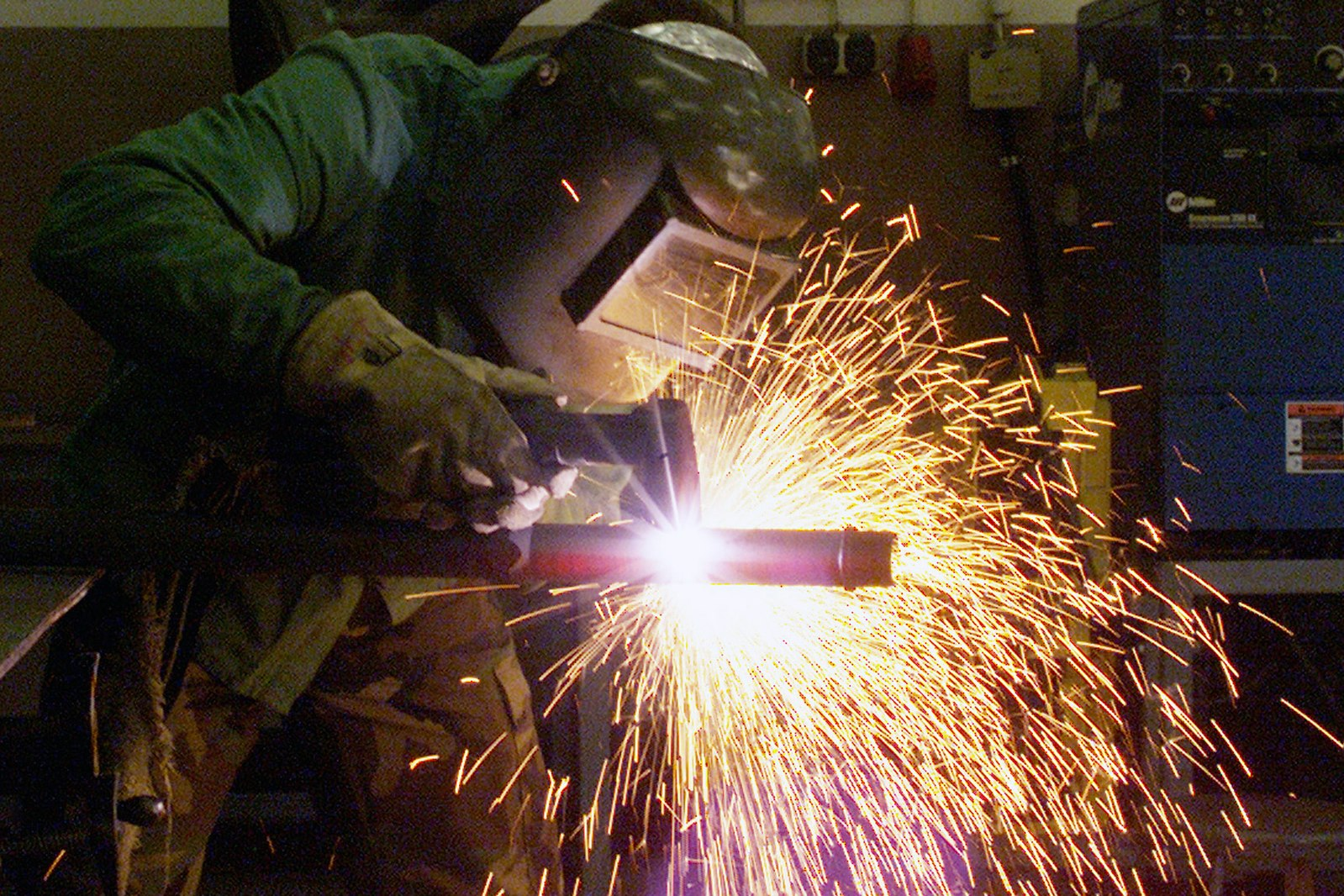
- Figure 14.16: US Air Force (USAF) Technical Sergeant (TSGT) Jeffrey Wright, Aircraft Metal Technician, 52nd Equipment Maintenance Squadron (EMS), uses plasma arc cutting torch to destroy a 30mm gun barrel, inside the welding shop at Spangdahlem Air Base (AB), Germany. The weapon was removed from an aircraft and set for destruction after reaching its serviceability date by Department of Defense. American Forces Information Service. Defense Visual Information Center. in the Public Domain; United States government work
Overview
A farmer makes repairs to a broken metal cowling on a combine harvester out in the field. A pipe welder works on welding the next section of a pipeline, which already stretches for many miles. A heavy equipment operator fixes a crack in a loader bucket at a jobsite. A new welding student strikes an arc for the first time. What do all these projects have in common? They utilize shielded metal arc welding (SMAW).
Often called stick welding (or simply arc welding by the older generations of welders), SMAW is one of the oldest and most reliable forms of electric arc welding. Robust, highly portable, and able to weld a wide range of metals, SMAW has been a staple process of the welding industry for over a century.
In this chapter, you will learn about the fundamental aspects of the SMAW process. You will be introduced to some of the history of SMAW and its current applications. You will be shown the components of the welding system and study techniques in order to become proficient in welding with this process.
Objectives
After completing this chapter, students should be able to:
- List some of the uses of the SMAW process in industry.
- Identify equipment associated with SMAW.
- Classify electrodes used for SMAW.
- Recall techniques for using SMAW.
Key Terms
- Alternating current (AC)
- American Welding Society (AWS)
- Amperage
- Arc
- Arc length
- Base metal
- Constant current (CC)
- Direct current electrode negative (DCEN)
- Direct current electrode positive (DCEP)
- Electrode
- Electrode holder
- Electrode lead
- Filler metal
- Flux
- Lack-of-fusion (LOF)
- Leading angle
- Multi-pass weld
- Oscillation
- Perpendicular angle
- Single-pass weld
- Slag
- Stringer bead
- Trailing angle
- Travel angle
- Travel speed
- Undercut
- Voltage
- Weave pattern
- Weld bead
- Weld pool
- Welding leads
- Welding power source
- Weldment
- Work angle
- Workpiece lead
Attributions
- Chapter opening image: SMAW by U.S. Department of Transportation, Federal Highway Administration in the Public Domain; United States government work

Overview
Recall movies you have watched showing Vikings or Samurai wielding swords. Now think of walking through a large city and looking up at the skyscrapers, driving your car or riding a bus over a bridge, opening your refrigerator, and cracking open a soft drink can. One thing all of these objects have in common is they are made of metals—even concrete structures are reinforced with steel. Indeed, if we did not have the technology to make things out of metals we would still be living in the Stone Age. Literally.
The general public is probably unaware of the importance welders/weldors have in our society. From the manufacturing of objects (ranging from cars and furniture to surgical equipment and everything in between), building and maintaining the equipment that manufactures objects, and the construction of buildings and infrastructure, practically every object surrounding you either is made of metal or was made or transported on equipment made of metal. And welders are the people who melt these metals (and sometimes glass and plastic) together.
Objectives
After completing this chapter, students will be able to:
- Understand the significance of welding in our modern world.
- Identify common career paths in the welding industry.
Key Terms
- Welding
- Blacksmith
- Electric arc welding
- Automatic wire feed welding
- Gas tungsten arc welding
- Metal alloys
- Carbon arc welding
- Forge welding
- Fusion welding
- Flux-cored wire feed welding
- Flux-cored arc welding (FCAW)
- Shielded metal arc welding (SMAW)
- Gas metal arc welding (GMAW)
- Gas tungsten arc welding (GTAW)
- Manual welding
- Semiautomatic welding
- Welder (weldor)
Attributions
- Chapter opening image: image released under the Pixabay License

.jpg)