34 History of SMAW
David Ridge
Development of SMAW
The first arc welding process was developed in the early 1880s by Auguste de Meritens (Lincoln, 1933, p. 1.1-2). It used carbon electrodes. The circuit was connected in direct current electrode negative (DCEN) configuration and the electrode holder was fixed in position and moved on a pivot to lower the electrode. This process was later refined toward the end of the 1880s by Nikolas de Benardos and Stanislav Olszewski (Lincoln, 1933, p. 1.1-2). These two scientists used a bank of storage batteries charged by a steam engine as a power source. They also decided to connect the circuit to run on direct current electrode positive (DCEP), and developed a handheld electrode holder to allow manual manipulation of the carbon electrode. This carbon-arc welding process proved to be very limited in what could be welded with it, primarily because the disintegrating carbon rod contaminated the base material with excess carbon deposits.
In 1888, a Russian inventor named Nikolay Slavyanov improved the carbon-arc welding process by replacing the carbon electrode with a metal one (“Shielded Metal Arc Welding,” 2023). In 1889, the American Charles Coffin made roughly the same development to the process independently of Slavyanov (Lincoln, 1933, p. 1.1-3). Using metal electrodes worked markedly better than the carbon electrodes because they eliminated the carbon contamination problem and introduced additional filler metal into the weld as the electrode melted. However, they still were only marginally useful for welding metals. The main problems were the low quality of the metal used for the electrodes and the lack of any way to shield the molten weld metal from elements in the air. This led to weak, brittle welds that could not be relied on for strength in high-stress applications.
In the early 1900s, Oscar Kjellberg of Sweden and Arthur Percy Strohmenger, an American, developed the first covered metal electrodes (“Shielded Metal Arc Welding,” 2023). The first iterations were not much better than the bare metals ones. However, in 1912 Strohmenger produced a heavily coated metal electrode that could produce clean welds with good mechanical properties (“Shielded Metal Arc Welding,” 2023). Although it wasn’t named as such at the time, this was the first real version of shielded metal arc welding.
Because of the high cost of producing the covered electrodes, unfortunately this form of arc welding did not become widely used until World War 1, when the need for faster production and repair of ships and other war-related vehicles became necessary. It wasn’t until after the war, in 1927—when a method of quickly and cheaply applying the coating to the electrodes by extrusion was developed—that the arc welding process really began to spread quickly as a means of production (“Shielded Metal Arc Welding,” 2023).
By the start of World War 2, arc welding with covered metal electrodes was the most widely used method of welding for industries such as shipbuilding, vehicle manufacture, oil refineries, railroads, and pipelines (Lincoln, 1933, p. 1.1-6). As the process has progressed over the past century, the main advancements have been related to the metal alloys used for the electrodes, the composition of elements in the coating material, and the types of power sources available (Lincoln, 1933, p. 1.1-6). Aside from these things, SMAW’s basic principles and concepts haven’t changed in over 100 years.
Today SMAW has been largely replaced by the faster, more efficient flux-cored arc welding process. However, it still holds a place in industry due to the relatively low cost and portability of its necessary equipment and SMAW’s ability to weld almost any metal used in manufacturing thanks to the wide variety of electrodes available. SMAW remains one of the most important welding processes for any welder to master and is usually one of the first processes students and new welders encounter.
Basics of the Process
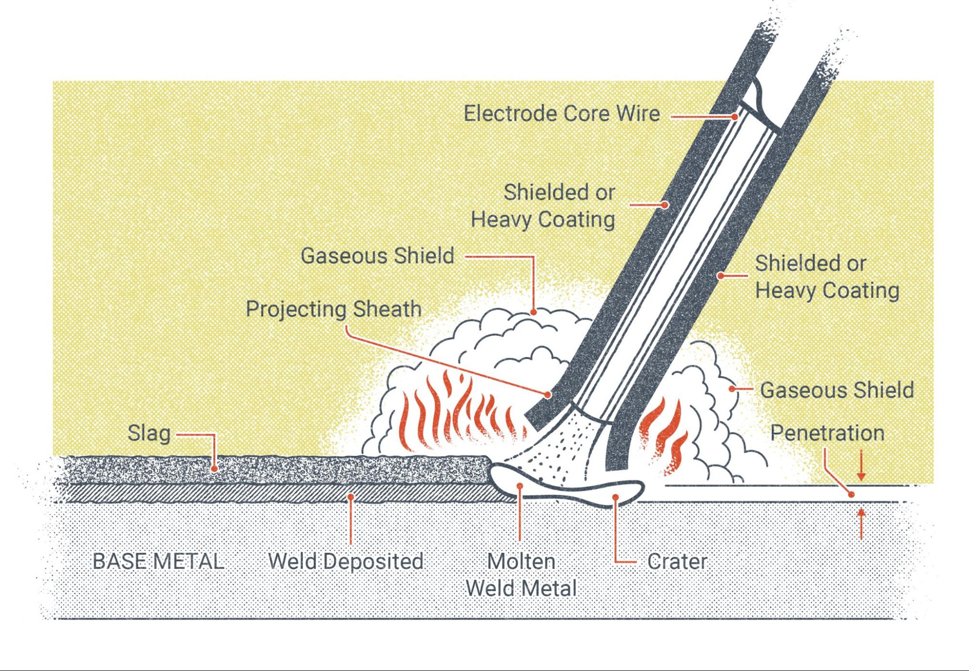
The SMAW process uses electricity to create an arc between a coated metal rod, called an electrode, and the metal to be welded, which is called the base metal. The electrode is coated in powdered material called flux, which is baked onto the rod. These coated electrodes are what led to the SMAW process being nicknamed stick welding.
The arc is somewhere between 6,000 and 11,000 degrees Fahrenheit (3,316-6,093 degrees Celsius). This is due to the resistance of the atmosphere to the flow of electricity (discussed in Chapter 5: Welding Machines). The arc melts the base metal and the filler metal of the electrode together to form the weld. As the arc melts the electrode, some of the elements in the flux coating are burned to create CO2 gas, and others are melted to form a substance called slag. The gas cloud created by the flux protects the weld by pushing the air away from the weld area, which is necessary because molten metal reacts badly with elements in the normal atmosphere. The slag forms a covering over the molten weld metal as it solidifies, which further protects it from the atmosphere, helps it hold its shape, and helps the weld cool at the correct rate.
The size, shape, and direction of the weld are controlled manually by the operator. The welder is responsible for adjusting the welding machine’s electrical settings and manipulating the electrode completely by hand.
Uses of SMAW in Industry Today
One of SMAW’s greatest benefits is its ability to weld the most common types of metal, thanks to the wide variety of electrodes on the market. SMAW is capable of welding everything from thin sheet metal to material that is several inches (or several feet) thick, as well as a wide variety of metals and alloys. With the correct electrode, the proper settings, and a skilled operator, many things can be welded with SMAW.
The main drawbacks of the SMAW process are that it creates a significant amount of dirt and debris, is inefficient regarding material usage, requires a higher level of skill from the welder than some other processes, and is a relatively slow process. Because of the lack of speed and efficiency, SMAW has been replaced by the much faster wire-feed welding processes in most high-production environments, and the general filthiness created keeps it from being used in situations that require precision and cleanliness, such as aerospace welding.
Still, SMAW has many applications in the modern world. It has uses in the shipbuilding and construction industries. It is often seen in mobile welding businesses, machine repair, and agriculture. It is also used extensively in pipeline welding and exclusively in underwater welding. As far as anyone can predict, the process won’t die out anytime soon.
Jessica Y.’s Welding Story
I didn’t come into welding through your typical routes. I wasn’t raised by parents who had laborious jobs or worked out in the garage, and while the high school I attended did have a welding shop class, I dropped out of school long before I had the opportunity to take it. I fell in with the wrong crowd, doing drugs and committing crimes. I found myself sitting in prison by the age of 22. I knew it was time for me to grow up and make some serious changes. I was fortunate enough that the institution I was in had a very intensive in-patient treatment program. I was even able to enroll in college classes that were provided by the local community college that had a contract with the prison. This was all the catalyst of change. I worked hard on overcoming my addiction and behavior problems and was able to work on my education, learn how to be a decent student, and pay my debt to society for the wrongs I had done. Three birds and one stone.
In the classwa, my instructor Ms. O was incredibly real and very honest that with multiple felonies, we would be more limited in employment opportunities and urged us to start thinking about a career field that would accept us felons. I knew I was comfortable in a shop environment, loved the thought of working with my hands, and wanted to build something I could be proud of. Ms. O passed out a career aptitude test where I was asked questions like, “Would you rather help a sick animal or build a fence?” I scored high in categories like construction worker, heavy equipment operator, and welder. I think it’s obvious which option I chose. Closer to my release date, Ms. O was able to put me in contact with the local community college in the area I was moving to. I applied for financial aid and enrolled in a two-year welding program the week that I got out. Once my mind was set on welding, I knew I had to follow through no matter how intimidated I might feel.
Not only was I in uncharted territory, but I had just spent time in prison and was still working to stay sober. I felt like I didn’t belong. I felt like I had a big scarlet letter “F” on me that everyone could see. But once I got my bearings, I found that school came easy to me and that my time locked up taught me discipline and good study habits. I also found that I wasn’t the only student that felt out of place, that there were lots of students that were there battling their own adversities. I found comfort in knowing that we were all there working on the next step to building a better life than the ones we once lived. I was the only female student in my class, but as luck would have it, my welding instructor was a fellow woman. Ms. K was genuinely supportive of me and the work I had been doing to turn my life around. She would challenge me to dig deeper into things and assert myself more to projects in and out of my welding class. She would tell me to strive for progress; perfection would come later. But most importantly, she taught me to always build up the women around me as she was doing and how, because in this industry we are few and far between, we must support one another. I would have never thought this possible for someone like myself. Before deciding on a welding career, it was hard to imagine I would achieve something bigger than working fast food or bagging groceries. Fast forward two years, and I had graduated with high honors, completing an Associates degree.
Then, graduated and with a new sense of confidence, I had to get out there and find an employer that was willing to give me a chance (I still had all the felonies to explain). I told myself that if a potential employer had issues with my past, then it was a company I wouldn’t want to be a part of. Ms. K came through again and pointed me in the direction of a company that was hiring, and once again I lucked out. I met with Ms. S, the owner of a local weld shop. I was incredibly nervous for the interview but knew that I had worked my tail off to get to that point. While in the interview, I waited for the right opportunity to tell her about my past, knowing she would come to see it on the background check. I explained to her that while yes, I had seven felonies that were all drug-fueled, it was nothing in comparison to the work I had done to change my life. I explained the various twelve-step programs I was in while incarcerated as well as the work I continued to do since being released. I made sure to include all my certificates of achievements in my resume. I wanted her to know I was serious about working and ready to prove myself. A few days later, I got the call; Ms. S told me she valued my honesty and would like to give me a shot to come work for her. I have now been employed full-time with the same company for five years and look forward to many, many more.
Choosing a career in the welding industry has been life-altering for me. It has made me into a woman I and my family can be proud of. It has given me financial stability and instilled in me a good work ethic. I am now married and about to have a baby girl. My husband, who has also overcome similar adversities, is a heavy equipment operator, and together we look forward to teaching our daughter that it’s good to work with your hands and raising her to know that you don’t have to go to some big fancy college and that there are great jobs in the trades. What she does with that will be up to her.
I often hear my foreman say that the skill of welding is only 20% of the work. The rest is in your head. This couldn’t be more true. It’s all about gaining the confidence in your abilities and not getting hung up on mistakes. Once you can achieve that, the rest will fall in place. No one ever becomes a journeyman welder overnight. It takes years of on-the-job training and thousands of hours of hood time. The key is to go into it with a good attitude, always be teachable, and remain humble; hard work pays off. And know that you belong there. I will forever be grateful for the strong women that helped build me up along the way and I am eager to pay it forward as new women come into the field.
Jessica Y.

Attributions
- Figure 8.1: How SMAW Works by Nicholas Malara, for WA Open ProfTech, © SBCTC, CC BY 4.0
- Figure 8.2: Shielded Metal Arc Welding by Prowelder87 is released under CC BY-SA 4.0
- Figure 8.3: SMAW by Mgschuler is released under CC BY 3.0
- Image of Jessica Y: © Jessica Y, used with permission.
- Image of Jessica Y welding: © Jessica Y, used with permission.
Making Cuts
Before you start, make sure you have all your PPE on. The following chart shows the recommended shade (ANSI Z49.1) you will need to protect your eyes.
|
Amperage |
Minimum Shade |
Recommended Shade |
|---|---|---|
|
Less than 20 |
4 |
4 |
|
20-40 |
5 |
5 |
|
40-60 |
6 |
6 |
|
60-80 |
8 |
8 |
|
80-300 |
8 |
8 |
|
300-400 |
9 |
12 |
Note: Table reprinted from ANSI Z49.1 (“Guide For Shade Numbers” pp. 9)
Once you are wearing the needed PPE to safely complete your cut, follow this process:
- Hold the touch perpendicular to the metal being cut.
- Pull the trigger and drag the torch across the metal.
- If you do not have a drag tip or shield you will want to hover about ⅛ inch for the material.
- Just like welding you will always want to practice on a similar piece of material before starting on your actual project. This way you can troubleshoot your settings.
- If you are not cutting all the way through you need to slow down and turn up your amperage.
If you find that you have excessive dross on the bottom of your cuts. This can be caused by going too slow. Increase your speed a little. It can also be caused by excessive travel speed so do not go too fast either. If you are not cutting all the way through your material you run the risk of the molten metal blowing back into your torch and at you.
If you are experiencing a negative kerf angle (the sharp part of the metal is at the top and drifts away at the bottom) you are too close. If you have a positive kerf angel (the part looks like it has a bevel on it) you are holding the torch too far away. If you are getting a square edge on your cut this is outstanding, keep it up.
Direction of your cut masters. This matters because of the swirl that is produced inside the torch. When cutting a part where you want to keep the inside of the cut, the travel direction should be clockwise. When cutting out the interior of a part (so you will keep the outside of the cut) you will want to travel counter clockwise. This will give you the best end product.
After you have made your cut it will be hot. You will want to be cautious when handling metal after it has been cut. Most of the dross should break off very easily with a chipping hammer.
Maintaining the System
Maintenance for a Plasma cutter is quite simple. Check all electrical connections before and after use. Replace the consumables in the torch when needed and the occasional blow down with compressed air. As always check the owner's manual for detailed instructions.
Special Safety Considerations
Safety is paramount when plasma arc cutting (PAC).
Electrical shock is a possibility. Always wear your PPE and do not operate if you are wet or have sweat through your gloves. Whenever possible, reduce the probability of being shocked. If using an extension cord concert the machine to the cord then the power and when disconnecting disconnect the power then the machine from the cord.
Fire is another hazard to be aware of. As you can see in most of the pictures there are lots of sparks. Make sure to check your surroundings before you start cutting and make sure you know where the nearest fire extinguisher is.
Compressed air is another safety concern when plasma arc cutting. It can puncture the skin and create debris that can get in your eyes. Be careful when using compressed air.
Both outside the visible light spectrum of the human eye, ultraviolet and infrared light can be hazardous and burn your eyes. Always wear the appropriate safety shade for your eyes. Please be sure to check the shade recommended by ANSI Z49.1 and presented earlier in this chapter to ensure you have proper protection for your eyes.
Machined torches and CNC machines have their own safety concerns the you will want to pay close attention to. Be sure to ask for specific safety guidelines and read the manufacturer’s warnings carefully before operating these machines.
Attributions
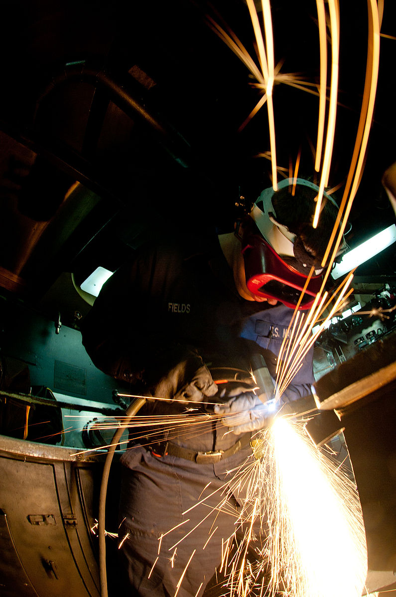
- Figure 14.15: US Navy 111128-N-OY799-092 Hull Maintenance Technician Fireman Tom Fields, from Brinnon, Wash., uses a plasma cutter in the sheet metal shop aboard by Mass Communication Specialist 3rd Class Kenneth Abbate in the Public Domain; United States government work
- Figure 14.16: US Air Force (USAF) Technical Sergeant (TSGT) Jeffrey Wright, Aircraft Metal Technician, 52nd Equipment Maintenance Squadron (EMS), uses plasma arc cutting torch to destroy a 30mm gun barrel, inside the welding shop at Spangdahlem Air Base (AB), Germany. The weapon was removed from an aircraft and set for destruction after reaching its serviceability date by Department of Defense. American Forces Information Service. Defense Visual Information Center. in the Public Domain; United States government work
An American National Standard. (2021). Safety in Welding, Cutting, and Allied Processes. In American Welding Society (pp. 1–72). https://aws-p-001-delivery.sitecorecontenthub.cloud/api/public/content/f524cc78ee9c4e00a703bbe12b2f368b
Giles, Z. (2022, April 14). The History of Plasma Cutting: The Evolution of Plasma Cutting. American Torch Tip. https://americantorchtip.com/blog/plasma-cutting-history-the-evolution-of-plasma-cutting/
Plasma, waterjet and laser cutting systems from Hypertherm. (n.d.). Www.hypertherm.com. Retrieved May 16, 2024, from https://www.hypertherm.com/en-US/global-landing-page/?returnUrl=751
Welding Basics
Now that you have all of the preliminary background information, you are ready to strike your first arc. (Be sure to read Chapters 2, 3, and 4 welding safety and PPE and ensure that you are familiar with and possess all the necessary PPE and tools required. If not, take this opportunity to do so.)
This section describes the techniques you will use when welding with the SMAW process. You will learn the basics of striking an arc, breaking an arc, and the acronym CLAMS, which stands for current, arc length, angle, manipulation, and travel speed. This acronym helps us remember the elements of good welding technique and can be applied to every welding process.
Getting Comfortable
The first step in making any weld is actually to get into a comfortable position. Being comfortable and having freedom of movement to perform the weld is imperative to making good welds, especially as a beginner. This can take whatever form makes sense to you, as everyone is different. However, consider the following points as general guidelines for good welding posture:
- Whether you are sitting or standing, try to keep your torso as upright as possible. Try to find something to brace your body or a leg against.
- If the object you are welding can be moved freely, try to position it at a height somewhere between your chest and your waist. This allows you to both see and reach the weld zone easily. If the object cannot be moved, instead try to position yourself so that the weld you are making is as close to the area between your chest and your waist as possible. Welding below your waist or above your shoulders will tire you out quickly and it is hard to see the weld.
- Hold the stinger (electrode holder) in your dominant hand, and then brace that hand with your off-hand. For example, if you are right-handed, you will hold the stinger in your right hand and then brace that hand with your left.
- Find something to rest the elbow or forearm of your bracing hand on. This can be almost anything: the workbench you’re using, a wall if you are next to one, or even a clamp attached to the piece you’re welding. It is important to understand that you don’t need to lean all of your weight on that arm—instead, it is there to steady you. As you will find out when welding, everything but the arc becomes dark through your hood. Because of this, your brain automatically thinks you are losing your balance and will cause you to sway. Having your arm in contact with a solid object will reduce this effect.
- Most of the movement during welding should come from your wrists and forearms. Avoid needing to move your elbows and shoulders and try to keep your elbows as low and close to your body as possible.
- Before actually welding, make a few test runs along the joint to be welded to ensure that nothing will impede your movement when you make the actual weld. Notice whether your bracing hand can easily slide along the joint without getting caught and if you can reach the entire length of the weld easily. Test runs can also help you to know if are in a good position to see the weld at all times.
Being comfortable during welding increases your stability and range of motion, reduces your rate of fatigue, ensures good visibility, and, overall, allows you to weld better for longer.
Striking an Arc
Once you have your welding machine and workstation set up and gotten into position, you will need to strike an arc to start welding. This sounds simple enough but requires practice to do effectively.
In order to initiate the arc with SMAW, you must touch the tip of the electrode to the base metal, then raise it slightly above the base metal surface. This is actually quite challenging because when you touch the live electrode to the grounded base metal, it creates a short circuit in the flow of electricity, which often causes the electrode to stick to the base metal.
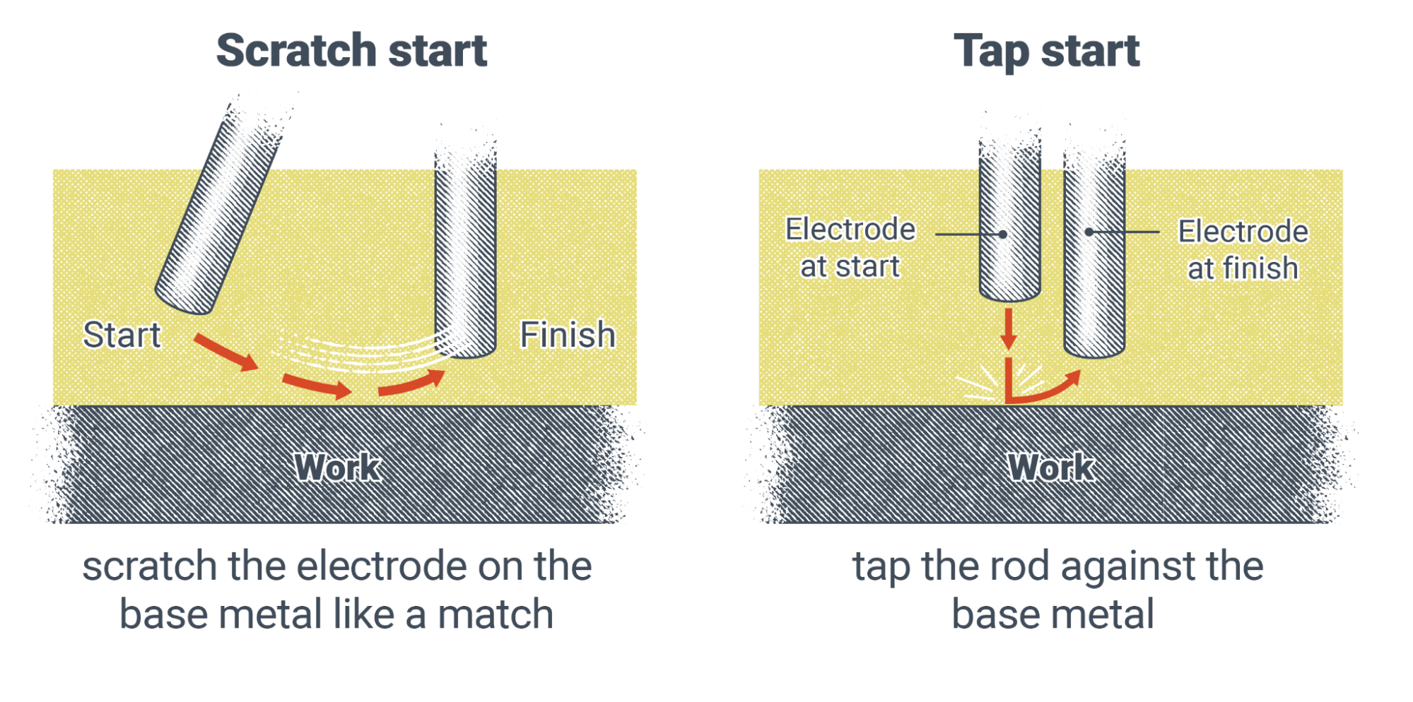
There are two basic techniques that can be used to prevent the electrode from sticking. In the first, you lightly scratch the tip of the electrode across the surface of the base metal for a short distance, much like striking a match. This motion should be done quickly and lightly—the more pressure you apply, the more likely it will be that the electrode will stick.
In the second technique, you hold the electrode slightly above the base metal surface, then move it straight down and tap the surface lightly before raising it slightly again. You can think of this motion like how you would strike a pool ball with a cue stick. In fact, many beginner welders start with this method by holding on to the end of the rod with their off-hand, much like a pool cue. Once the arc is started, they move their hands back to brace their dominant hands.
While these techniques will help with starting the arc, they are not guaranteed to keep the rod from sticking every time. Sticking happens at some point to every welder who uses SMAW, no matter their experience level. Try not to get frustrated if it is difficult to strike an arc right away. With practice, you will become proficient.
Breaking the Arc
We should also cover how to break or stop the arc. When you come to the end of a weld, you might be tempted to slowly pull the electrode away from the base metal—but you should resist, as this is an incorrect method.
Instead, as you come upon your stopping point, hold the arc at the end of the weld for a second or two. This helps fill in the weld crater. Then quickly snap the electrode away from the base metal, either in the direction you were traveling or back over the weld. This will efficiently break the arc and prevent any unwanted arc strikes outside the weld zone.
C is for Current
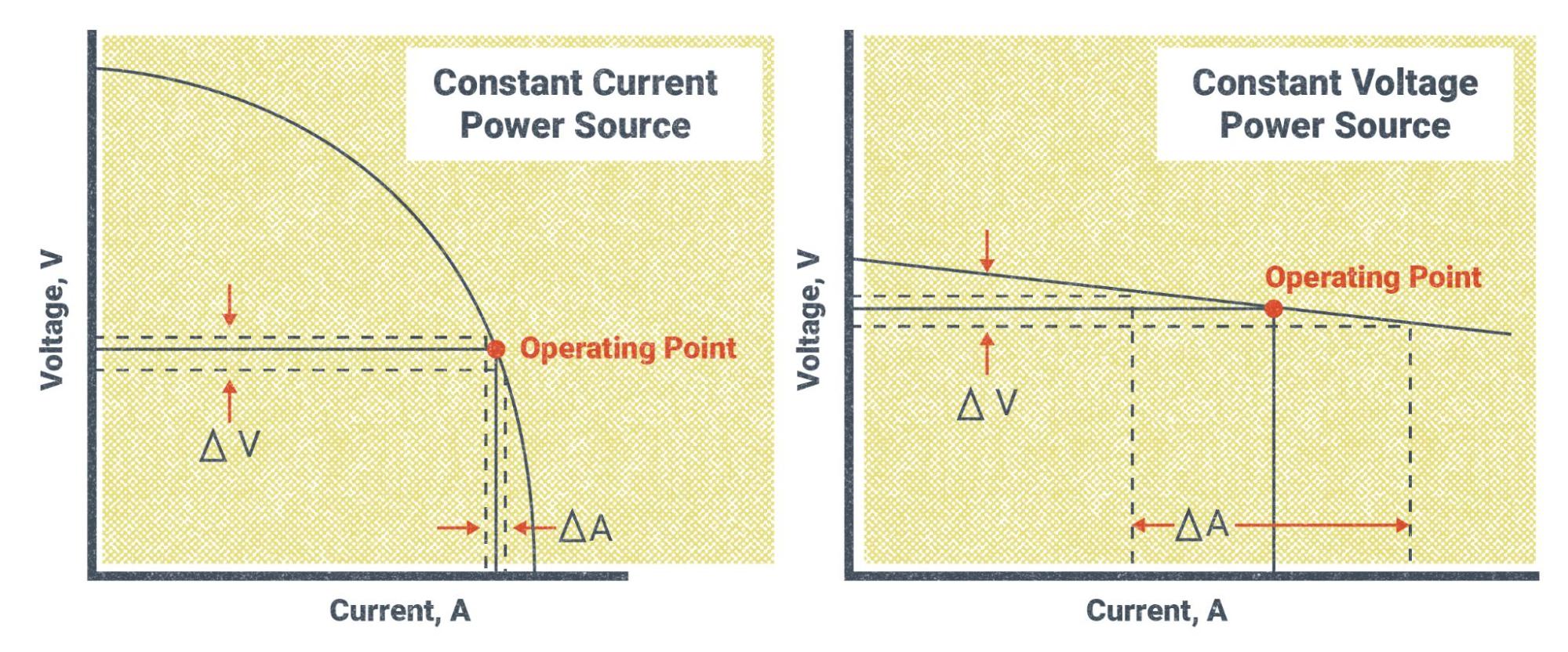
Now we’ll progress into the elements of the CLAMS acronym. The first letter, C, stands for current. The moment you turn your welding machine on, you must decide on the type and amount of welding current needed. SMAW uses constant current (CC) welding power. If your welder is a multi-process machine and isn’t automatically set to CC, then you will need to change the type of welding power. Iinstead of CC you may see a selection labeled “Stick” or “SMAW”—those will set the machine to CC power.
Next, you will need to determine your polarity. Looking at the classification for the electrode you are using, you can determine whether the machine should be set to DCEP, DCEN, or AC. Select the correct polarity by adjusting the switch, knob, or button on the welder or by changing which port the electrode and work leads are plugged into (refer to SMAW Setup in Section 8.2).
Once you have the correct power type and polarity you can set your amperage. The most important current setting for SMAW, amperage has the greatest effect on the quality of weld penetration and weld bead shape. It is very important to select the correct amperage for the electrode you are using and the base metal to be welded. As an example, a one-eighth inch diameter E7018 has a recommended amperage range of 90–160 amps (the recommended amperage for each electrode can be found in its product information from the manufacturer). However, this must be balanced against the base metal thickness. So if you were to weld on a piece of one-quarter inch thick steel plate, you would find that the appropriate amperage would actually be around 110–125 amps. Thicker plate would take more amperage, and thinner plate would take less.
The process of troubleshooting the correct amperage range takes some time and experience, especially since there are a number of other factors that influence it, which can include welding position, weld joint configuration, the length of your leads, and preheat, among other things. Even the machine you are working with can be a factor, as each different welding machine may run slightly differently.
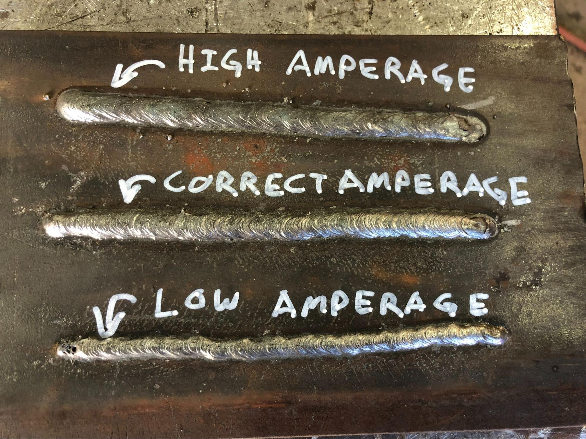
When on the job, your supervisor can instruct you on an amperage range as a good starting point, but you will likely still have to fine-tune your settings from there. The best way to know how to troubleshoot your amperage setting is to practice doing it as much as possible. Look for some of the following issues when welding, which can indicate incorrect amperage:
- If the finished weld bead is narrow with a high crown and little penetration, your amperage may be too low.
- If the finished weld bead is wide and flat with excessive penetration and a lot of spatter, your amperage may be too high.
- If the arc is difficult to start and the electrode sticks to the base metal constantly when striking the arc, or if it seems like the arc is almost sputtering out during welding, your amperage may be too low.
- If, while welding, the arc digs into the base metal at the edges of the weld or even burns through the base metal, your amperage may be too high.
- If you notice that the weld pool is excessively long and shaped like a teardrop rather than an oval, your amperage may be too high.
Another control that may be adjusted is the arc-dig or arc-force setting. This setting is not essential for making a good weld, but can help make welding easier. If your machine has this control, you can adjust the “crispness” of the arc, meaning it will be narrower and seem to drive more into the base metal. A higher arc-dig setting will make the arc more crisp, though it does not measurably improve penetration. This is useful for welding in a tight corner or groove or for welding an open root (discussed in Chapter 15: Weld Identification). This setting also helps keep the electrode from sticking to the base metal when holding a short arc length. Turning the arc-dig down will create a “softer” arc, meaning it will be wider and less forceful. This helps if you are trying to spread out the weld pool more when welding on a flat surface or on thinner material.
Before moving on, a note about safety with regards to current settings is that none of the settings or controls mentioned should be adjusted during welding. When working with certain older welding machines it is even recommended that the machine be powered off before adjusting settings like polarity. Doing so prevent damage to the machine, but also ultimately protects you since a damaged machine can cause you harm.
L is for Arc Length
The second letter of the CLAMS acronym stands for length, referring to arc length: the distance that the arc travels through the air. It is measured from the tip of the electrode to the surface of the weld pool. Arc length is an important welding variable with any welding process, and particularly with processes that use CC welding power.
In the section about setting the current for welding, you may have noticed that there was no mention of a control for voltage. Both amperage and voltage are a part of every electrical current, so where is the voltage control for SMAW? In a sense, arc length is the voltage control, and it’s manually adjusted by your motions throughout the weld (remember that voltage is electrical pressure or force). The distance that the arc must travel through the open atmosphere determines the voltage applied to the weld. As the arc length increases, the voltage increases, and vice versa. This is because it requires more voltage for the arc to travel across a greater distance.

Because SMAW uses CC power, the overall electrical power in watts always remains the same. This means that changes in voltage due to changes in arc length will also change the amperage being applied to the weld. If the voltage increases, the amperage will decrease, and vice versa.
To consider an example, let’s say you set the amperage on the machine to 80 amps and then maintain an arc length that requires 24 volts. Using the formula from Chapter 5, we know that 24V × 80A = 1,920W. At that amperage setting, the welding machine will always try to maintain that 1,920W output. If the voltage were to increase to 30V because you increased the arc length, the amperage would automatically decrease to 64A because 30V × 64A = 1,920W. Conversely, let’s say the voltage decreased to 20V because you held a tighter arc length. We know that the amperage will increase to 96A because 20V × 96A = 1,920W. It is important to note that although this is the theory of how CC welding power works, in in reality these numbers will not be perfect. This is simply because no welding machine or welding conditions is perfect. However, these formulas provide a close approximation of what actually takes place.
Voltage determines the fluidity of the weld pool. More voltage means the molten metal is more fluid, and less voltage has the opposite effect. What you need to take away from this is that voltage affects how easily the weld pool spreads out across the base metal.
Welders must maintain a balance with the arc length. If the arc length is too long, the arc becomes violent and the weld pool becomes too hot and fluid. This usually results in defects like excessive spatter and undercut, as well as poor weld quality in general. Increasing the arc length will, at a certain point, not create a weld pool but will simply deposit globs of molten metal on the surface of the base metal. On the other hand, if the arc length is too short, the weld will not spread out and will pile up on itself, which leads to defects like overlap (also called cold roll) and lack-of-fusion (LOF) because the arc is not hot enough to melt the filler and base metals completely. Further shortening the arc length will result in the end of the electrode sticking in the weld pool.
In general, the correct arc length for most electrodes is said to be equal the electrode’s diameter. This means if you were welding with an E7018 electrode with a diameter that is one-eighth of an inch, you would try to maintain a one-eighth inch arc length. Doing so is easier said than done. You must remember that the electrode is melting off and getting shorter as you progress along the weld. One of the most difficult skills for a new welder to master is the ability to lower the electrode towards the weld pool at a consistent rate. However, with time and practice, you will become proficient.
Arc Blow
Before moving on to cover the next letter in the CLAMS acronym, we should discuss a problem that can occur during welding. Known as arc blow, it causes the arc to wander haphazardly with little ability for the welder to control it. It can cause weld defects such as undercut, LOF, and slag inclusions.
It’s a phenomenon that occurs due to the magnetic field created by the flow of electricity through the base metal. Arc blow is hard to predict or control because it is related to the shape and joint configuration of the weldment and the amount of welding power flowing through it. Some methods for trying to control arc blow include:
- Move your work clamp so that you are welding away from it
- Use multiple work clamps attached at different points on the weldment
- Use AC, if possible
- Weld at the lowest amperage possible
- Keep as tight of an arc length as possible
- Try adjusting the arc-dig to be more crisp
Though these tips can help, sometimes it is impossible to eliminate arc blow completely. Experimenting with different strategies will help you decide how to best handle an instance of arc blow.
A is for Angle
The next letter in the CLAMS acronym is A, standing for angle. You may hear this referred to as rod angle or electrode angle (or gun angle for MIG welding and torch angle for TIG welding). Rod angle actually refers to two different angles: travel angle and work angle.
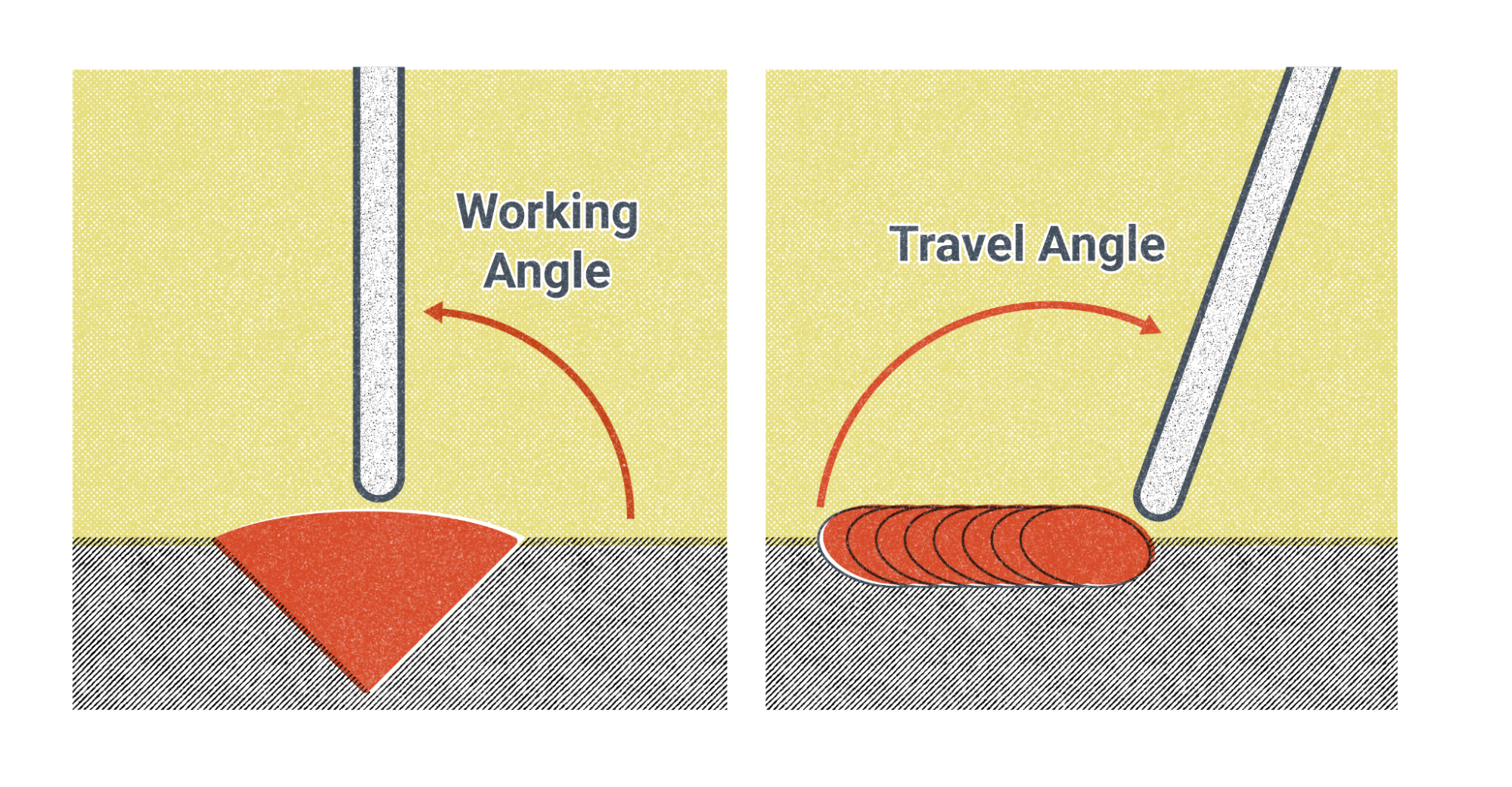
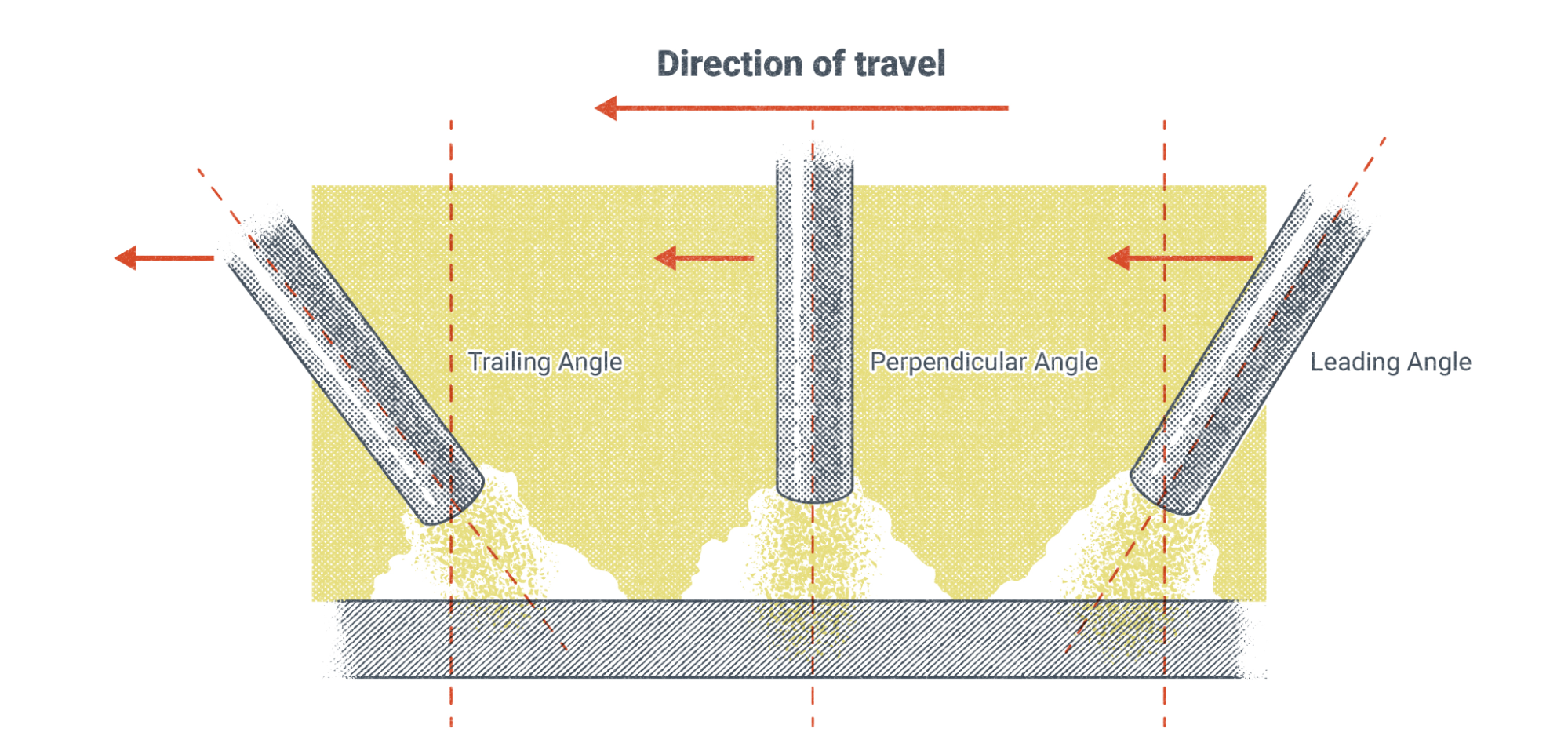
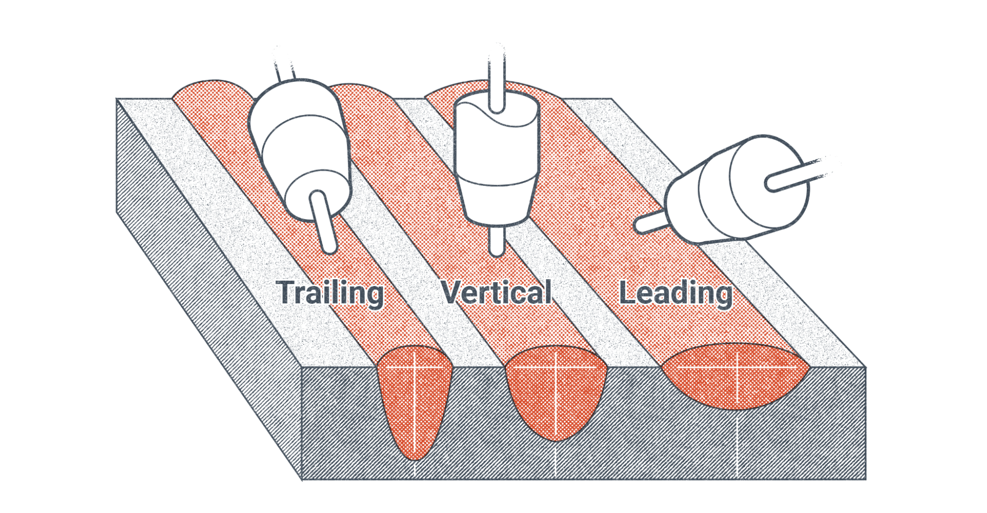
Travel angle is the angle of the welding rod in relation to the direction the weld is progressing. There are generally considered to be three different travel angles.
A trailing angle is when the tip of the electrode is angled away from the direction the weld is traveling while the end held by the electrode holder is angled toward the direction of travel. This puts the weld pool slightly behind the tip of the electrode, and you may hear it said that you are “dragging” the weld. This is the most common travel angle used for SMAW.
A leading angle is formed when the tip of the electrode points toward the direction of travel and the end of the electrode in the stinger trails behind. This puts the weld pool slightly ahead of the tip of the electrode, and you may hear it said that you are “pushing” the weld. A leading angle is often less desirable with SMAW because of the tendency for slag to be deposited ahead of the weld and then trapped underneath or within the weld as the weld pool passes over it. These slag inclusions are a major defect in a completed weld and might cause it to fail under extreme stresses. While the risk of this defect is a major concern, some experienced welders may make effective use of the leading angle.
A perpendicular angle is a travel angle that puts the electrode straight up and down over the weld pool at 90-degrees to the plane of the weld.
There are different reasons to use any of these travel angles. Welding position has a lot to do with it, as well as weld joint configuration. For example, you are more likely to use a leading angle when welding in the vertical up position, but you may prefer a trailing angle for flat or overhead welds. Sometimes the placement of a weld is in such a constricted space that it is only possible to use one angle. Other times, the placement will force you to change angles partway through the weld.
Another reason you may choose one angle over another is the thickness of the base metal compared to the desired weld penetration. It is generally accepted that a trailing angle produces a weld with deep penetration and a tall, narrow weld face whereas a leading angle produces a wide, flat weld with less penetration. A perpendicular angle is somewhere in between.
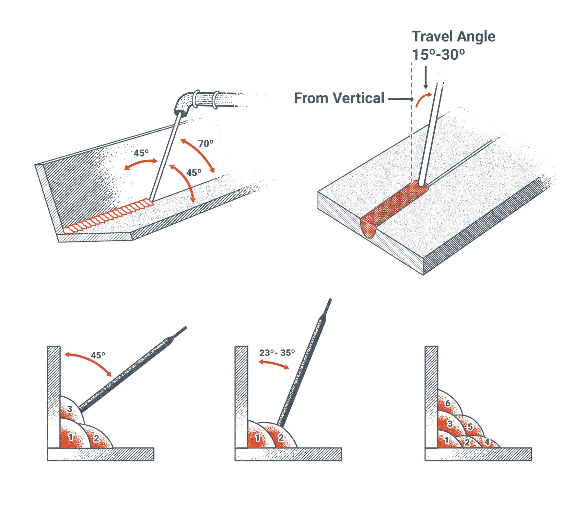
Whichever angle you use, it is important to note that extreme angles are undesirable. This means that whether you are using a trailing or leading angle, you should attempt to keep the electrode between 15-degrees to 30-degrees from perpendicular.
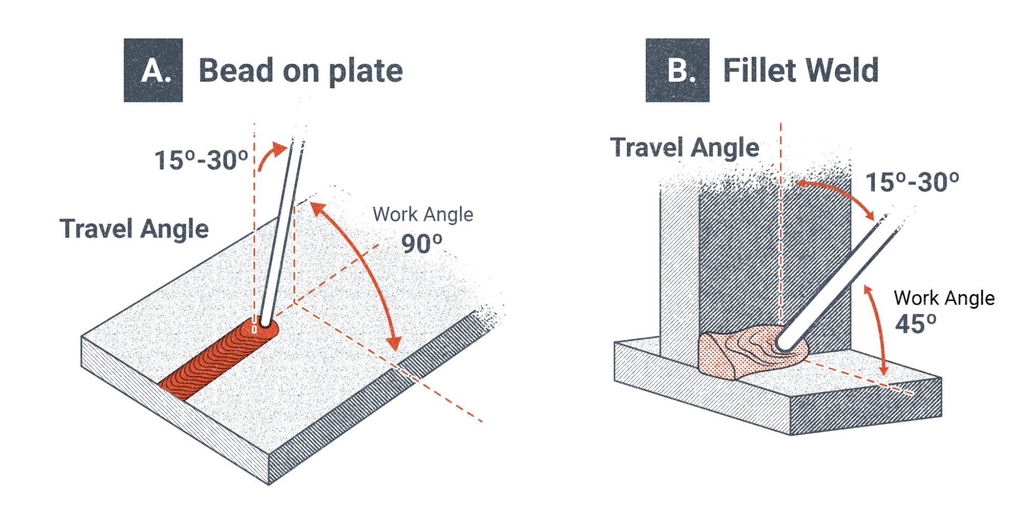
Next is the second type of rod angle, which is work angle. It is the angle of the electrode in relation to the base metal. Work angle is somewhat subjective, but the basic idea is that the work angle is used to force weld metal more to one side of the weld than the other. This is not always necessary, so a perpendicular work angle is used to deposit weld evenly.
Perhaps the best example of work angle is on a multi-pass weld, such as in a T-joint or weld groove. Each successive weld pass requires you to adjust the work angle slightly to force the weld one way or the other. Unfortunately, there are no solid rules about work angle, and it is something that every welder learns to account for through experience.
The angle of your welding rod is an important factor when making any weld. New welders often have trouble maintaining a consistent rod angle while welding because the act of moving the rod and their hands together along the weld joint while continually lowering the rod as it shortens is unfamiliar. Practice finding a comfortable position and being able to freely move your hands along with the electrode holder and rod and, in time, you will find it easy to keep a proper rod angle.
M is for Manipulation
The next letter in the CLAMS acronym is M, which stands for manipulation, though some might say it stands for motion. Either way, the focus is on what movement you’re making with the welding rod. It’s important to note that this is not the movement of maintaining your arc length, your rod angle, or your progress along the weld joint. Rather, what we are talking about here is what’s referred to as the weave pattern or oscillation. The main purpose of manipulating the electrode in this way is to make the weld bead wider. There are a number of different weave patterns or oscillations that can be used. Each one has a purpose and, depending on the situation, some are better or worse.
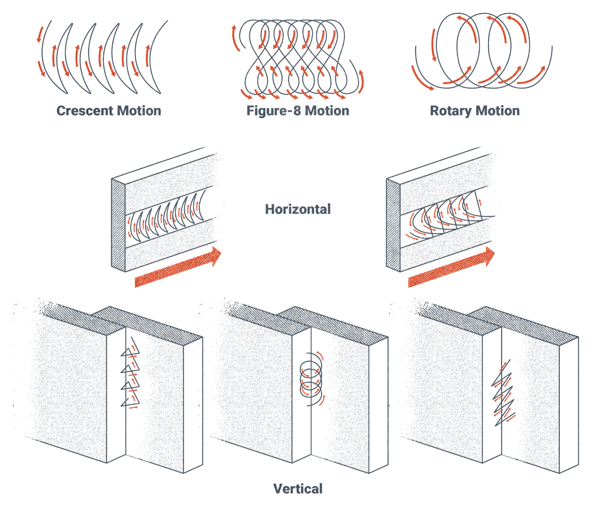
The patterns shown in Figure 8.35 are just a few of the weave patterns that have been developed. Simply by modifying a pattern that you are familiar with, you could create a new pattern. There is no hard rule that tells you which weave pattern or oscillation you should use at any given time or instructs that you need to use any such movement. It is often quite acceptable to make stringer beads, which are straight weld beads made without side to side motion. Usually it is up to the welder to decide which manipulation they want to use. You will learn through trial and error which ones work for specific situations, although it is helpful to ask more experienced welders for tips in this area.
S is for Speed
The last letter in the CLAMS acronym is S, standing for speed. Speed is the most determinative factor influencing how big the weld bead turns out. There are two speeds to be aware of: travel speed and manipulation speed. Travel speed is how fast you are progressing along the weld joint and manipulation speed is how fast you are weaving or oscillating. Accordingly, manipulation speed is not a factor when making stringer beads.
f you are working off of a welding blueprint, there will almost always be a callout for the weld size on every weld (blueprints and welding symbols are covered in Chapter 16). Adjusting your speed is the best way to control the size of a weld: A slower speed will make the weld bigger, and a faster speed will make it smaller. This is true whether you are making a single-pass weld or multi-pass weld. For SMAW, a general rule for weld size is that you want the weld pool to be approximately twice the diameter of the electrode you are using. For example, if you are using an electrode whose diameter is one-eighth of an inch, you would want to keep the weld pool at about one-quarter of an inch wide.
Weld defects can result if your speed is incorrect for the amperage and size of rod you are using. A speed that is too fast will often cause undercut at the edges of the weld. Too slow of a speed will likely cause overlap. Paying close attention to the weld pool as you are welding will help you determine how fast or slow you should be moving.
The Importance of the Weld Pool
Now that we have finished defining the CLAMS acronym, I think you will agree that there is a lot to pay attention to during welding. Being able to focus on each factor simultaneously is one of the biggest challenges for new welders. It’s best to start small and try and focus on one thing at a time until you get the hang of it. For example, spend a whole training day just striking an arc, another day focusing on your arc length, and another practicing your angle or travel speed, etc. Learning to weld takes a considerable amount of patience, but if you are diligent and stick with it you will be surprised how quickly you will improve.
In addition to the CLAMS factors, however, there is one more aspect of making a weld you need to pay close attention to, and it is quite possibly the most important: being able to see and read the weld pool at all times. If you cannot see the weld pool, you must adjust or change whatever it is that is keeping you from seeing it. The importance of this cannot be stressed enough.
Learning this skill is, by far, the most difficult thing for a new welder to do. Inexperienced welders tend to use the arc or their rod as the focal point of their vision. As you develop your welding skills, you must train yourself to focus primarily on the weld pool and monitor everything else through your peripheral vision. Good welders know that the weld pool tells them everything they need to know about how the weld is going. This is true of any welding process.
With SMAW, the weld pool should be roughly oval or egg-shaped. Look out for these issues:
- If the weld pool is elongated or has turbulence on the surface, that can mean that you are running too hot and need to turn down your amperage.
- A narrow weld pool can indicate an amperage that is too low or a travel speed that is too fast.
- An overly wide weld pool can mean a travel speed that is too slow.
- A weld pool that is off to one side of the electrode can indicate a bad work angle.
Practice keeping the weld pool as your focal point and learning to interpret its indicators. Ask questions of instructors and other welders if you don’t understand something about it. Once you can effectively interpret what the weld pool is telling you, you are well on your way to being a better welder.
Special Safety Considerations
Before we conclude this chapter, it would be a good idea to go over some safety considerations that are commonly associated with SMAW. These are in addition to general safety considerations for welding, such as hazards like smoke, sparks, hot metal, sharp edges, and electricity. Refer to Chapters 2, 3, and 4.
With SMAW, there are some specific hazards that you should keep in mind. Remember that when the welding machine is on, the electrode holder is always live. Damaged electrode holders can have exposed contact surfaces that could accidentally strike an arc if touched to the base metal. This also means that any time an electrode is held in the holder, the electrode is live. Never set the electrode holder down with an electrode still loaded in it. Be aware of any broken flux on the electrodes. Any place where the flux is broken off exposes the metal rod underneath and presents the potential for an accidental arc strike. Aside from being dangerous, unintentional arc strikes on the base metal are undesirable, as in many welding situations arc strikes outside the weld zone are considered a defect and may cause the piece to be scrapped.
Another common occurrence with SMAW is related to arc strikes—the end of the electrode may get stuck when you attempt to initiate the arc. New welders are often surprised by it the first time it happens to them. Be aware that if the rod sticks, the electricity continues to flow through the circuit even though there is no visible arc. This can be hazardous for two reasons. First, the machine is operating at the working amperage and voltage. You would not want to touch any of the contact points and become part of the circuit. And second, if the electrode is not immediately broken off the surface of the base metal, it will begin to heat up. After a few seconds, you will see the electrode glow bright orange. That means the rod is in excess of 1,500 degrees Fahrenheit. You would not want to touch the rod at that temperature, even with a gloved hand. If you find that you cannot easily break the electrode off the base metal when it sticks, the next best thing to do is to let go of the rod with the electrode holder. Wait about 10 seconds and then you should be able to easily snap the electrode off of the base metal.
There are a few final things to be careful of. If you are in a situation where you are welding full-time or at least several hours consecutively, beware of fatigue. Welding is a physically and mentally demanding job, and fatigue can set in without you noticing. People are the most careless and at risk for an accident when they are tired. Take breaks at appropriate times, keep yourself hydrated, and be aware of whether you are feeling symptoms of heat stress or heat stroke. Always try to find a way to be as comfortable as you can, whether this means feeling as cool as possible or in a position that does not cause strain, as this will help delay the onset of fatigue.
There is one particular practice you want to avoid related to fatigue. The electrode holder and the welding lead are heavy, and over time your arms will start to feel strained. The temptation when this happens is to wrap the lead around your arm or body. While it is fine to loosely drape the lead over a shoulder, you should avoid wrapping the lead around yourself in a coil. A coiled copper conductor with electricity running through it is an electromagnet—and in this case you would be at the center of it. However, high levels of electromagnetic flux have been shown to be dangerous to humans.
As with any industrial environment, there are always hazards present when welding, whether with SMAW or any other process. Many thousands of welders perform their work every day without incident. These welders know that the best safety practices are to be competent, have common sense, and be aware of their environment. If you do the same, you will not need to endure hazards.
Attributions
- Figure 8.25: Shielded Metal Arc Welding by Weldscientist is released under CC BY-SA 4.0
- Figure 8.26: Striking the Arc by Nicholas Malara, for WA Open ProfTech, © SBCTC, CC BY 4.0
- Figure 8.27: Welds at Different Amperages by David Ridge, for WA Open ProfTech, © SBCTC, CC BY 4.0
- Figure 8.28: Arc Length and Voltage by Nicholas Malara, for WA Open ProfTech, © SBCTC, CC BY 4.0
- Figure 8.29: Volt/Amp Curve by Nicholas Malara, for WA Open ProfTech, © SBCTC, CC BY 4.0
- Figure 8.30: Electrode Angle by Nicholas Malara, for WA Open ProfTech, © SBCTC, CC BY 4.0
- Figure 8.31: Travel Angle by Nicholas Malara, for WA Open ProfTech, © SBCTC, CC BY 4.0
- Figure 8.32: Angle and Weld Profile by Nicholas Malara, for WA Open ProfTech, © SBCTC, CC BY 4.0
- Figure 8.33: 15-30 Degree Angle by Nicholas Malara, for WA Open ProfTech, © SBCTC, CC BY 4.0
- Figure 8.34: Work Angle by Nicholas Malara, for WA Open ProfTech, © SBCTC, CC BY 4.0
- Figure 8.35: Weave Patterns by Nicholas Malara, for WA Open ProfTech, © SBCTC, CC BY 4.0
This textbook, Welding Theory Fundamentals, has been edited by Cary Flanigan for use in the welding program at Clover Park Technical College from other openly licensed texts. A solid understanding of welding theory is essential for building the skills and confidence needed to excel in today’s welding industry. This resource has been thoughtfully developed with the technical college student in mind, offering clear, practical explanations of core welding concepts.
From the principles of heat and fusion to the behavior of metals and the science behind various welding processes, this textbook lays the theoretical groundwork for hands-on welding proficiency. Additional emphasis is placed on safety, joint design, and the relationship between welding variables and weld quality. Supporting content on material properties and welding codes enhances students’ readiness for real-world applications.
Whether you are new to welding or seeking to reinforce your foundational knowledge, this textbook is designed to align with the curriculum and goals of Clover Park Technical College’s welding program.
Summary
GTAW is an arc welding process utilizing a non-consumable tungsten electrode and inert shielding gas to protect molten puddles. GTAW gives welders a very high degree of control over the molten puddle. This process is used widely in industries such as food processing equipment, casting repair, aerospace, spacecraft, and more.
The weld machine can have a wide variety of settings to help with puddle manipulation, arc shape, and even cleaning. The type of shielding gas used—argon, helium, or a mixture—affects the penetration of the weld. There are many alloys of tungsten, so the type of tungsten used can be a personal preference for each welder.
Also, cleanliness and fit up are incredibly important factors in GTAW and should not be taken lightly.
Review Questions
- What was GTAW originally developed for?
- What do you do if it starts to hurt as you are welding?
- Stop
- Suck it up
- Grit your teeth
- Make funny noises until you are done
- What is the safety concern about using a thoriated tungsten?
- What percentage of heat is on the tungsten when welding in straight polarity (DCEN)?
- 30%
- 70%
- 50%
- None of the above
- What is the approximate melting temperature of pure aluminum?
- 1,200 degrees Fahrenheit
- 3,700 degrees Fahrenheit
- 1,300 degrees Fahrenheit
- 5,500 degrees Fahrenheit
- What is the approximate melting temperature of aluminum oxide?
- 3,700 degrees Fahrenheit
- 1,200 degrees Fahrenheit
- 1,330 degrees Fahrenheit
- 5,500 degrees Fahrenheit
- What is one of the advantages of using a gas lens over a colet body?
- Greater tungsten stickout
- Better gas coverage
- Less gas consumption
- All of the above
- What is an autogenous weld?
- A weld using only the base material
- A weld that is made for the auto industry
- A weld that is made automatic
- All of the above
- Why is it important to fill the crater when welding aluminum?
- When using GTAW, what should melt the filler rod?
- The arc
- The puddle
