35 SMAW Equipment and Setup
David Ridge
Components
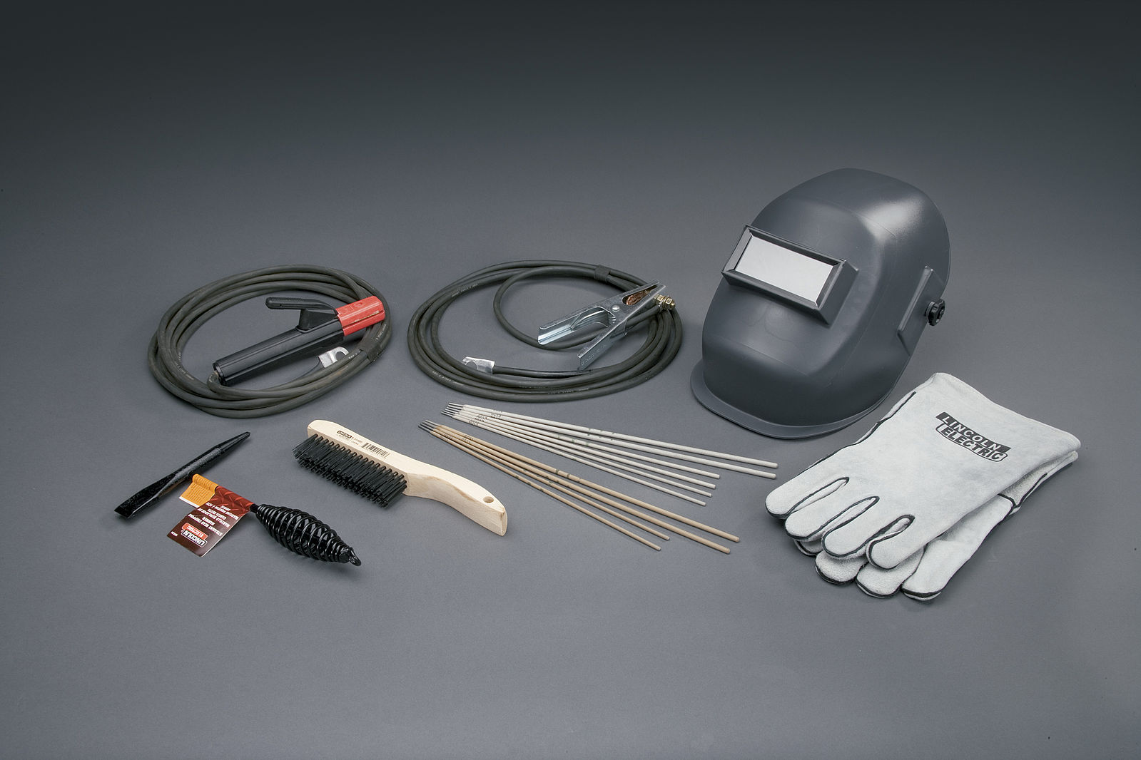
SMAW is one of the simplest welding processes as far as the amount of equipment needed. There are only four main components to the system:
- a welding power source,
- a workpiece lead,
- an electrode lead, and
- coated metal electrodes of the appropriate alloy.
The following sections discuss these components in detail.
Welding Power Source
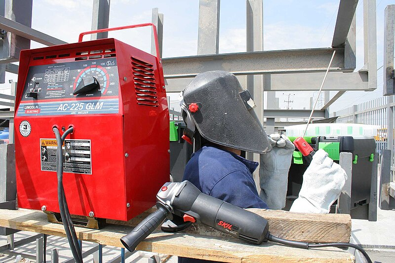
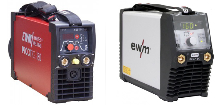
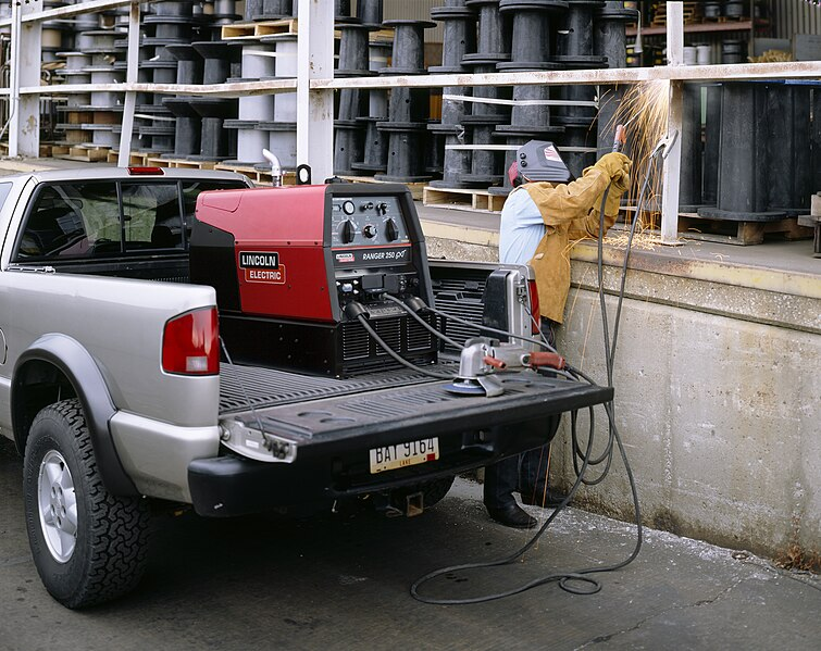
A welding power source is a machine capable of producing the specialized electrical current necessary for arc welding. These machines can vary widely in design, capability, and size, but, in general, they can be divided into three types: transformers, inverters, and engine-driven varieties. You will often hear the welding power source called a welding machine or simply a welder on the jobsite.
Welding power sources will be discussed in greater detail later in this chapter, and they are also covered in Chapter 5: Welding Machines.
Workpiece Lead
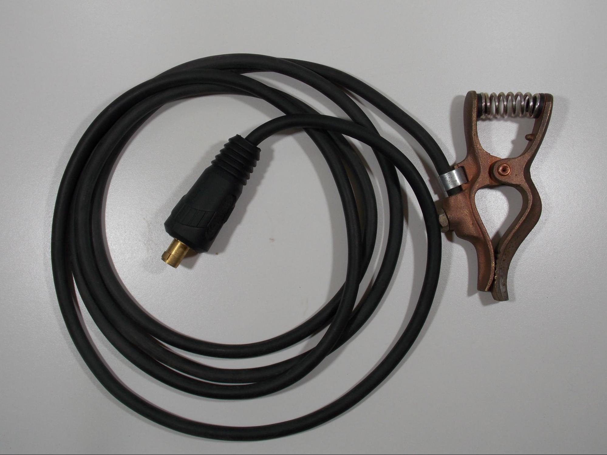
The workpiece lead is used to make the electrical connection between the welding machine and the base metal. You may hear the workpiece lead called the work lead or a ground lead (although this is inaccurate).
Welding leads are made of many small strands of copper wire twisted together into a cable and covered in a protective rubber sheath. Welding leads vary in diameter and length depending on the welding application.
The workpiece lead is attached to the base metal using either a clamp or a lug. A lug can be connected to a threaded stud, which is then welded to the base metal. These clamps and lugs are usually made of copper or brass; however, you may see some clamps made of steel. Though less common, there are also magnetic work clamps.
The other end of the workpiece lead is connected to the welding machine via a special plug called a twist-lock connector. This plug inserts into a receptacle on the welding machine and then twists to lock it in place. If not connected in this way, the lead is usually attached using a lug, or in some cases, it is permanently wired into the machine.
Electrode Lead
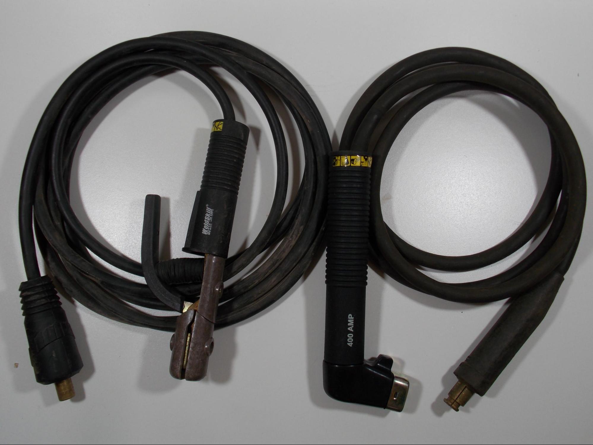
The electrode lead runs from the welding machine to the electrode holder. This is the piece that the welder holds in their hand in order to make the weld. You may often hear this piece called the stinger or the whip.
The electrode holder transfers the welding current to the electrode. There are several styles of electrode holders, and the most common are the alligator clamp style and the twist-lock style.
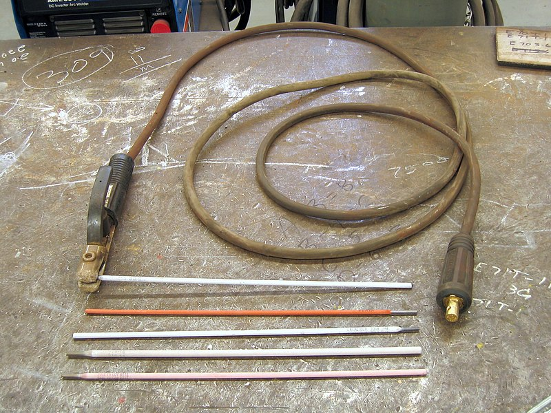
Coated Metal Electrodes
The SMAW electrodes are metal rods commonly ranging from 9–18 inches in length, although longer ones may be found. These rods usually range from one-sixteenth of an inch to one-quarter of an inch in diameter. Larger diameters are available but are usually only used for special applications.
The rods are sheathed in a flux coating. The flux has several purposes, the first of which is to protect the weld from the atmosphere during welding. This is primarily accomplished by the gas cloud and the slag cover that was mentioned earlier. Another way that the flux helps remove contamination from the weld is through deoxidizers, which are chemical elements such as silicon or manganese. These elements chemically clean the weld by attaching themselves to contaminants, such as sulfur, while the weld metal is a liquid, then floating them to the surface to become part of the slag.
Other components of the flux include arc stabilizers and fluxing agents. Arc stabilizers help maintain the welding arc during welding. An electric arc is naturally unstable and wants to wander and fluctuate in intensity (for a comparison, think of how crooked and uneven a lightning bolt is). Arc stabilizers keep the arc aimed where the operator wants it, help keep the heat of the arc focused on the weld pool, and help prevent the arc from sputtering or cutting out. Fluxing agents (not to be confused with the flux coating itself) make the weld metal more fluid, allowing it to flow out from the point where the arc meets the base metal. Even though molten metal is in a liquid state, it is very viscous and has a high surface tension. This property keeps the weld from spreading out over the base metal, making it pile up in one narrow area. Fluxing agents help counteract this effect.
The type of metal that can be welded with each different SMAW electrode is determined by the metal alloy that the rod is made of, as well as the type of flux coating that it has. Also, the diameter of the rod and the type of flux determine the type and amount of electrical power needed to make the weld. A system for identifying the different welding electrodes has been developed by the American Welding Society (AWS)—this system and its application will be discussed later in this chapter.
Setting Up the Welding System
Although SMAW does not require a lot of equipment and setting up and adjusting the welding system is not difficult, there are some key points that should be taken into account when preparing to operate a welder for SMAW.
This section discusses how to safely set up a SMAW system.
Safety Considerations
When setting up the welding system, it is necessary to consider the amperage ratings of components such as welding leads, electrode holders, clamps, and connectors. Each of these components comes in a range of sizes that are rated for different amperages.

The amperage rating for each component can be found in the user’s manual, product information slip, or printed on the component itself. It’s essential to be sure you are using components that are rated for the amperage you will be using because using a component at an amperage beyond its safe working rating can damage that part or other parts of the welding system. Always refer to the manufacturer’s recommendations when setting up a welding machine. This will help you understand how much power your machine and its components are rated for and the necessary electrical safety requirements.
Damage to parts may occur in other ways as well. Welding shops and construction sites can be harsh environments that result in damaged system components, which can be dangerous when working with hundreds of amps of electricity. All of the parts that are electrically “hot” are shielded to keep you from coming into contact with them, but damage could mean the live electrical components become exposed. Additionally, damaged parts almost always cause resistance in the welding circuit, which causes heat. For example, a worn out work clamp can get so hot from the additional resistance that it can cause burns if you touch it. Testing electrical connections to see if it is hot before touching it is always a good idea, especially if you have been welding consistently for a while. Another aspect of added resistance in the system is that it almost always makes your welder run poorly, making it very difficult to make a good weld. Before welding, have any damaged parts repaired or replaced and check all connections in a welding system to make sure they are tight. Loose connections can also cause heat to build up in the system, which can, in turn, cause damage.
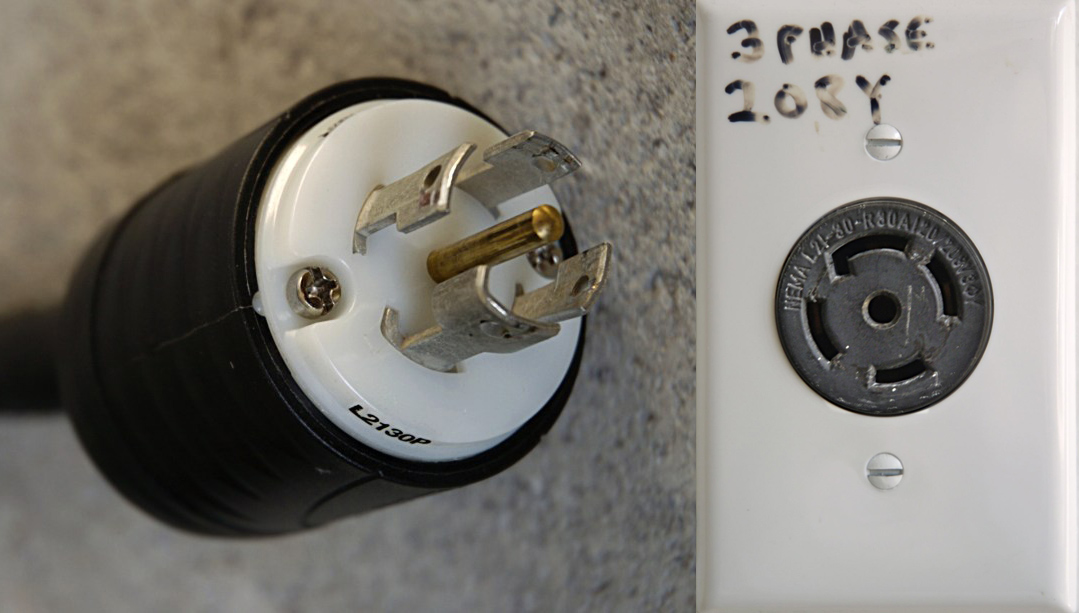
One last safety consideration to be mindful of when setting up your welding system is the service power you are plugging the machine into. While some welders can be plugged into a standard 110V/120V wall outlet, most production welding systems require a 220V/240V or even a 440V/480V circuit. Even if you can plug a welder into a standard wall outlet, welders usually require a 20 amp circuit breaker at minimum, which is not standard in most residential circuits. In the case of higher voltage circuits, a 30 amp or 50 amp breaker may be required. It is very important that you be sure your electrical supply is adequate for the machine you are running.
All work performed on electrical service supply should be done by a professional, and it is never your responsibility as a welder to work on these systems. If you encounter any damaged systems or equipment, do not attempt to fix the problem yourself. Instead, follow proper lockout/tagout procedures and notify the appropriate personnel.
SMAW Setup
Once you have ensured that all parts are in proper working order, you can begin to set up the welding system. The first step is to plug the welding power source into the appropriate wall outlet. If the outlet is at least a 220V/240V outlet, the plug and receptacle may be a twist-lock connector (meaning that you insert the plug and twist clockwise to keep the cord from falling out).
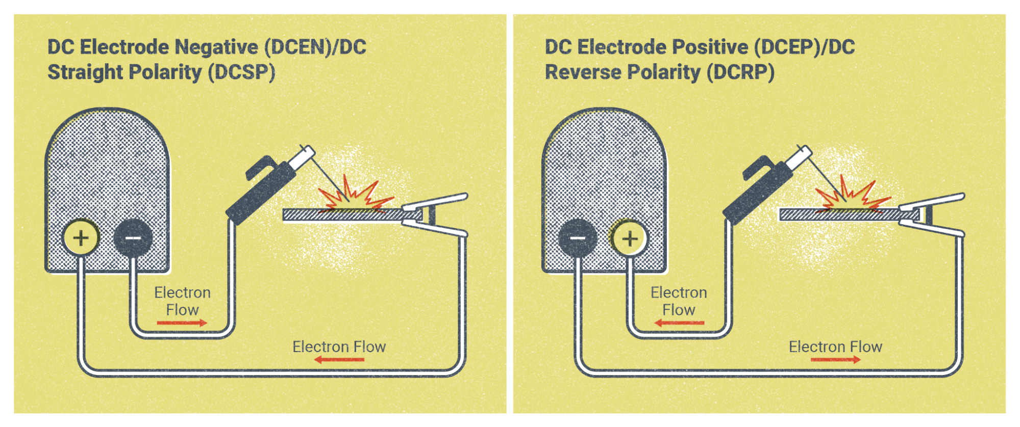
The next step is to attach the welding leads to the welder. The welder should have two different attachment points: one will be positive, and the other negative. The electrode you will use determines how you need to hook up the leads. Most welding electrodes require the welding circuit to be connected in DCEP. This means that the electrode lead is plugged into the positive terminal of the welder, and the work lead will be plugged into the negative terminal. If you needed to connect the leads in DCEN configuration, you would simply switch the electrode lead to the negative terminal and the work lead to the positive terminal.
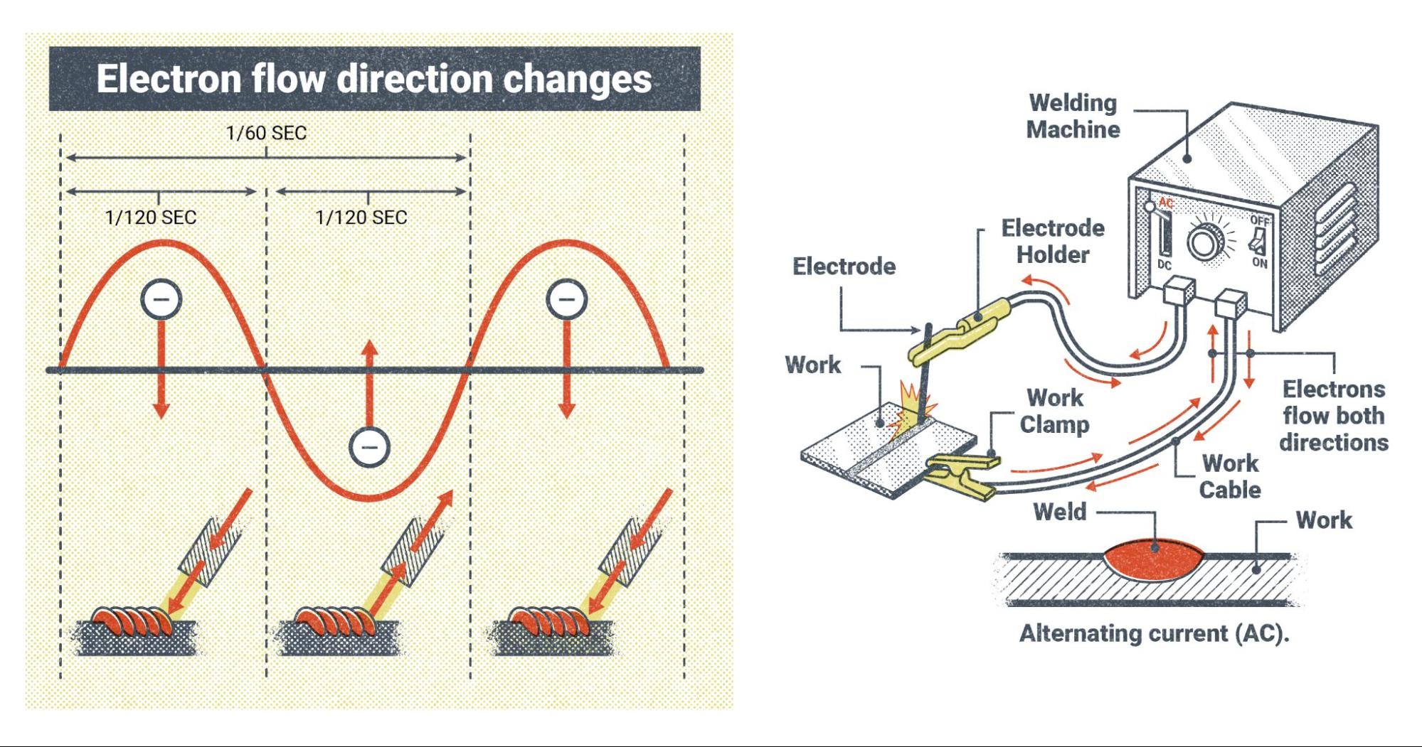
If the welder has the capability to run on alternating current (AC), it won’t matter which terminal the leads are connected to because the machine will automatically change the polarity 120 times per second.
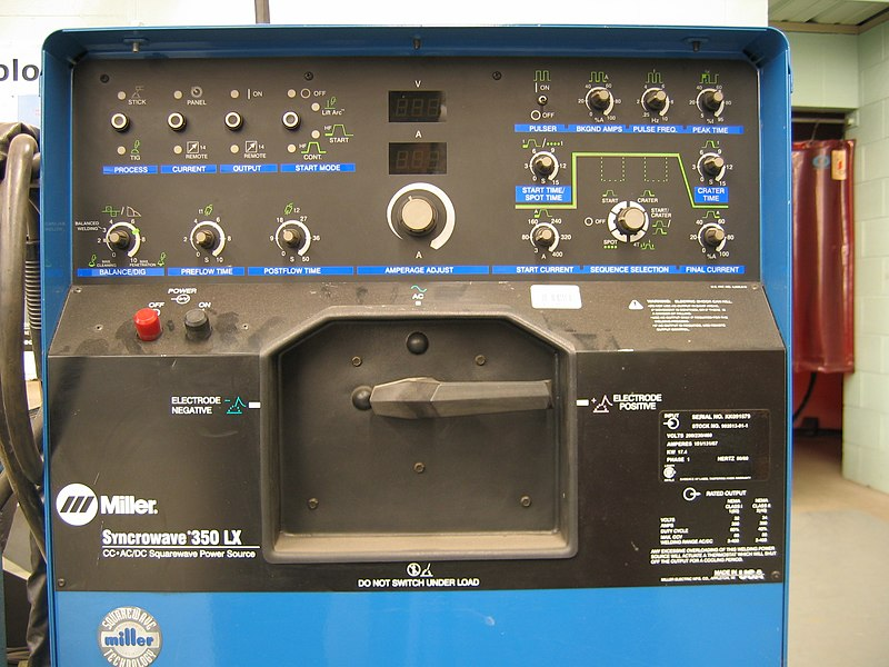
Some welding machines don’t have the option for you to change where the leads are connected. Instead, there will be a switch or a knob that will allow you to select which welding polarity you want.
The electrode holder and work clamp will be attached to the electrode lead and work lead respectively. At this point, you should be able to turn the machine on and proceed to the next step in setting up for SMAW.
SMAW Controls and Settings
Once you have turned the power on, you will need to determine your settings via the controls on the welder. With SMAW, you will likely only have between one and four different controls. The first to adjust, if the machine is equipped with one, would be the polarity selector. The next and most important control is your amperage setting. We will discuss specific amperage settings later in this chapter; for now, it is enough to say that amperage is the primary control for adjusting how the welder runs during welding, and this setting will have the most effect on how your weld turns out. Your machine may have no other controls, but it will always have an amperage control.
The last two controls do not appear on every welder. The first of these is the arc-control setting, which we’ll cover later in this chapter. The purpose of this setting is to make minor changes in how the welding arc behaves, which could make certain welding situations easier to manage. The other possible control is the hot start function, which helps start the arc at the beginning of the weld. The SMAW process is notorious for being difficult to start the welding arc, so this setting could help.
One thing to note about SMAW controls and settings is that you should never adjust them while you are actively welding, as this may damage the machine. Making adjustments while the machine is on is alright, though. Also, if you are using a multi-process machine to weld you may see additional control options. When the machine is set to the SMAW process, most of these controls will be disabled and only the ones mentioned in this section can be used.
Attributions
- Figure 8.4: SMAW accessories by Mgschuler is released under CC BY 3.0
- Figure 8.5: Red Lincoln welding plant and welder working on some steel beams by muygocho is released under CC BY-SA 2.0
- Figure 8.6: Schweißgeraete by EWM AG is released under CC BY-SA 4.0
- Figure 8.7: SMAW Field Shot by Mgschuler is released under CC BY 3.0
- Figure 8.8: Workpiece Lead by David Ridge, for WA Open ProfTech, © SBCTC, CC BY 4.0
- Figure 8.9: Electrode Lead by David Ridge, for WA Open ProfTech, © SBCTC, CC BY 4.0
- Figure 8.10: Arc welding electrodes and electrode holder.triddle by Triddle in the Public Domain; Public Domain dedication, not CC0
- Figure 8.11: Different Electrode Holders by David Ridge, for WA Open ProfTech, © SBCTC, CC BY 4.0
- Figure 8.12: L21-30 plug and receptacle by tholme is released under CC BY-SA 3.0
- Figure 8.13: SMAW DC Setup by Nicholas Malara, for WA Open ProfTech, © SBCTC, CC BY 4.0
- Figure 8.14: SMAW AC Setup by Nicholas Malara, for WA Open ProfTech, © SBCTC, CC BY 4.0
- Figure 8.15: Welding power supply-Miller-Syncrowave350LX-front-triddle by Triddle in the Public Domain; Public Domain dedication, not CC0
1F: Flat Fillet Test Position
1G: Flat Groove Test Position
2F: Horizontal Fillet Test Position
2G: Horizontal Groove Test Position
3F: Vertical Fillet Test Position
3G: Vertical Groove Test Position
4F: Overhead Fillet Test Position
4G: Overhead Groove Test Position
5F: Multiple Position Fillet Test Position (Pipe axis is horizontal and pipe not rotated)
5G: Horizontal Position Groove Test Fixed Position
6G: Inclined Groove Test Position
6GR: Inclined Groove Test Position with a Restriction Ring
A: Amps
AAC: Air Arc Cutting
ABANA: Artists-Blacksmiths Association of North America
ABS: American Bureau of Shipping
AC: Alternating Current
AD: Anno Domini, medieval latin for in the year of our Lord
AISC: American Institute of Steel Construction
ALARA: As Low As Reasonably Achievable
AM: Additive Manufacturing
ANSI: American National Standards Institute
AOC: United States Architect of the Capitol
API: American Petroleum Institute
ASME: American Society of Mechanical Engineers
ASNT: American Society of Nondestructive Testing
ASTM: American Society of Testing and Materials
AWS: American Welding Society
BBQ: Barbeque
BHN: Brinell Hardness Number
BLM: Bureau of Land Management
BPVC: ASME Boiler and Pressure Vessel Code
°C: Degree Centigrade
CAC: Carbon Arc Cutting
CAC-A: Carbon Arc Cutting - Air
CAD: Computer Aided Design
CAW: Carbon Arc Welding
CBO: United States Congressional Budget Office
CC: Constant Current
cm: centimeter
CV: Constant Voltage
CDC: United States Centers for Disease Control and Prevention
CFH: Cubic Feet Per Hour
CFM: Cubic Feet per Minute
CFR: US Code of Federal Regulations
CJP: Complete Joint Penetration
CL: Center Line
CLAMS: Current, Arc Length, Angle, Manipulation, and Travel Speed
CNC: Computerized Numerical Control
CP: Constant Potential
CPSC: United States Consumer Product Safety Commission
CTWD: Contact Tip to Work Distance
CWI: Certified Welding Inspector
dB: decibel
DC: Direct Current
DCEN: Direct Current Electrode Negative
DCEP: Direct Current Electrode Positive
DCSP: Direct Current Straight Polarity
DCRP: Direct Current Reverse Polarity
DE: Destructive Examination
DIY: Do It Yourself
DLA: United States Defense Logistics Administration
DOC: United State Department of Commerce
DoD: United States Department of Defense
DOE: United States Department of Energy
DOI: United States Department of the Interior
DOL: United States Department of Labor
DOSH: Division of Occupational Safety and Health
DOT: United State Department of Transportation
DP: Deep
DT: Destructive Testing
EBW: Electron Beam Welding
ECT: Eddy Current Testing
°F: Degree Fahrenheit
FCAW: Flux Cored Arc Welding
FCAW-G: Flux Cored Arc Welding - Gas Shielded
FCAW-S: Flux Cored Arc Welding - Self Shielded
FHWA: Federal Highway Administration
FMA: Fabricators & Manufacturers Association of America
FRP: Fiber Reinforced Plastics
FSW: Friction Stir Welding
ft: feet
FW: Flash Welding
GAWDA: Gas and Welding Distributors Association
GMAW: Gas Metal Arc Welding
GMAW-P: Gas Metal Arc Welding - Pulse Spray Transfer
GMAW-S: Gas Metal Arc Welding - Short Circuit
GTAW: Gas Tungsten Arc Welding
HAZ: Heat Affected Zone
HIC: Hydrogen Induced Cracking
Hz: Hertz
IFI: Industrial Fasteners Institute
IIW: International Institute of Welding
INL: Idaho National Laboratory
IPM: Inches Per Minute
IR: Infrared
IQI: Image Quality Indicator
kg: kilogram
ksi: thousand pounds per square inch
L&I: Labor and Industries
LANL: Los Alamos National Laboratory
lbs: pounds
LBW: Laser Beam Welding
LOC: United States Library of Congress
LOF: Lack of Fusion
LLC: Limited Liability Corporation
LLNL: Lawrence Livermore National Laboratory
LT: Leak Testing
m: meter
MAG: Metal Active Gas
MIG: Metal Inert Gas
mm: millimeter
MT: Magnetic Particle Testing
NASA: National Aeronautics and Space Administration
NASCAR: National Association for Stock Car Auto Racing
NAVEDTRA: Naval Education and Training Center
NAVSEA: Naval Sea Systems Command
NDE: nondestructive Examination
NDT: nondestructive Testing
NHRA: National Hot Rod Association
NIOSH: National Institute for Occupational Safety and Health
NPS: National Park Service
NREL: National Renewable Energy Laboratory
NRR: Noise Reduction Rating
OAC: Oxy-acetelyne Cutting
OAW: Oxyacetylene Welding
OFC: Oxy Fuel Cutting
ORNL: Oak Ridge National Laboratory
OSHA: United States Occupational Safety and Hazards Administration
PAC: Plasma Arc Cutting
PAPR: Positive Air Purifying Respirator
PAUT: Phased Array Ultrasonic Testing
PAW: Plasma Arc Welding
PJP: Partial Joint Penetration
PNNL: Pacific Northwest National Laboratory
PPE: personal protective equipment
psi: pounds per square inch
psig: pounds per square inch gauge
PT: Die Penetrant Testing
PW: Projection Welding
PWHT: Post Weld Heat Treatment
pWPS: preliminary Welding Procedure Specification
REA: United States Rural Electrification Administration
RPM: Revolutions per Minute
RSEW: Resistance Seam Welding
RT: Radiographic Testing
RW: REsistance Welding
SAR: Supplied Air Respirator
SAW: Submerged Arc Welding
SDS: Safety Data Sheet
SMAW: Shielded Metal Arc Welding
SS: Stainless Steel
TIG: Tungsten Inert Gas
TSP: Tri Sodium Phosphate
TWA: Time Weighted Average
TYP: Typical
UN: Unless Noted
UNO: Unless Noted Otherwise
USGS: United States Geological Survey
UT: Ultrasonic Testing
UV: Ultraviolet
V: Volts
VT: Visual Testing or Examination
W: Watts
WA: Washington State
WABO: Washington Association of Building Officials
WFS: Wire Feed Speed
WISHA: Washington Industrial Safety and Health Act
WPS: Welding Procedure Specification
WSDOT: Washington State Department of Transportation
WWI: World War I
WWII: World War II
Electrode Classification
Electrodes for GMAW welding are referred to as wire or wire consumables. The term consumables refers to how the electrode becomes part of the weld and gets “consumed” since it starts in wire form but gets transformed into the weld bead by heat during the process. The wire chosen for the weld in this process should match or be extremely similar to the chemical and mechanical properties of the base metal. The welding wire is classified by a letter and numbering system. The American Welding Society created, designed, and maintains this classification system.
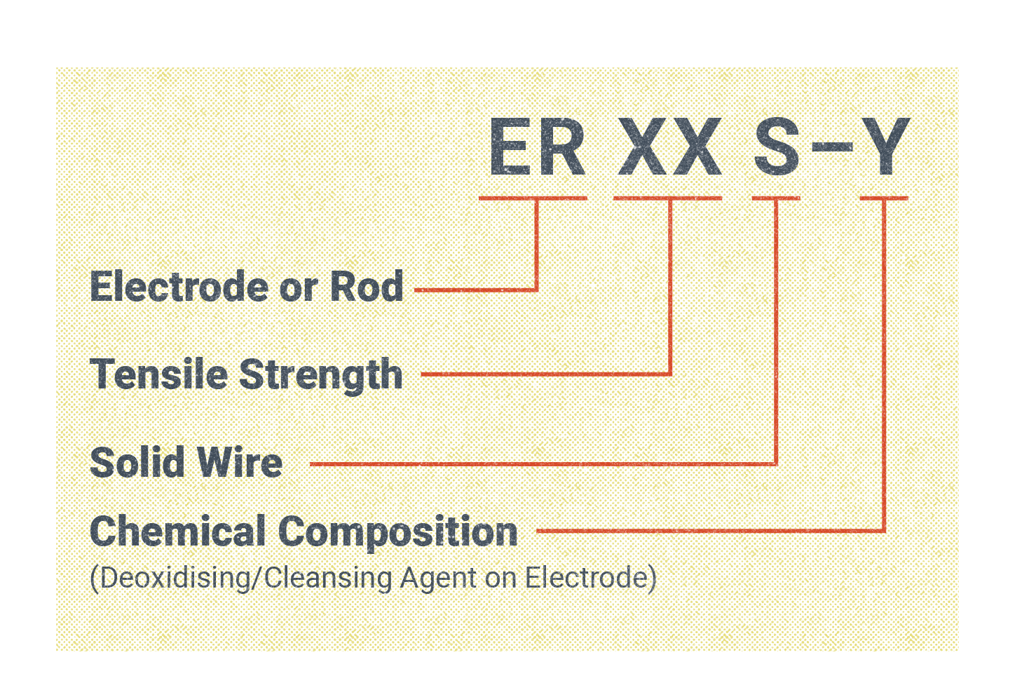
Figure 10.14 shows the classification. A GMAW electrode starts with E, which simply stands for electrode, followed by the letter R, meaning rod. The R lets the user know that this particular electrode can also be used as a filler electrode in gas tungsten arc welding (GTAW), which is referred to as a “non-current carrying rod.” The GTAW process is covered in Chapter 11.
The next set of characters in the classification is numbers. In Figure 10.14 it is represented by an XX placeholder, but the numbers indicate the tensile strength of the wire in 1,000 pounds per square inch (psi). If a 70 appears, that means the wire’s tensile strength is 70,000 lbs. The recommended tensile strength may change depending on what material the welder is working on, and, in the case of copper and copper-alloy bare wire, it may be eliminated altogether. Note that choosing a higher tensile strength weld wire than needed is not always better, as the heat, shielding gas, transfer mode, thickness of material, and joint preparation must also be considered.
The next letter designation in Figure 10.14 is S, which means the electrode wire is solid. These are sometimes called hard wires. In contrast, FCAW uses tubular wires, indicated by a T. Other letters in this place on GMAW electrodes may be C, for composite. This is used for GMAW metal core wire welding in congruence with the spray transfer process, which will be covered later in this chapter.
Lastly, the letter Y at the end acts as a placeholder. On an electrode, a number between 2 through 7 that refers to the wire’s chemical composition will appear there.
Metal-cored wires are tubular wires like that used in the fluxed-core process. However, unlike the wires used in FCAW, GMAW wires are not filled with flux—instead, they contain metallic powders such as iron. These wires offer some of the same benefits as their solid wire partners, such as being slag-free, able to weld a multitude of thicknesses, create better fusion on the toes of the welds, and a generally wider root profile. However, composite tubular wire is limited to use in the flat or horizontal weld positions due to the fluidity of the weld puddle.
There are also designations for aluminum, stainless, and low-alloy steel electrodes. Two examples of these differing classifications would be the electrode ER309L for stainless. In this case the ER still remains the same; however, 309 refers to the grade of stainless steel and L indicates that it is a low-carbon electrode. Another is ER4043, an extremely common aluminum welding wire. Again, ER means that this is an electrode rod. The first number, 4, is an indication that this wire is part of the 4000 series of aluminum alloy, and then the 043 refers to the amount of silicone that has been added. All of these wires are manufactured and used in an array of sizes typically ranging from 0.023 inches to 0.125 inches in diameter and, when paired with the appropriate shielding gas, create desirable welds.
Shielding Gasses
GMAW can be used in combination with a multitude of shielding gasses such as argon, CO2, helium, hydrogen, nitrogen, and oxygen. The most commonly used for GMAW are a variation of three different shielding gasses: argon, CO2, and helium.
Not all shielding gasses are the same, and they each have their own effects on the weld in combination with the wire and base metal they are interacting with. For example, argon and helium are both considered inert gasses, which means they are nonreactive to chemicals in their environment. Inert gasses are also known as noble gasses. Using these inert gasses is where the term MIG welding originates. However, using active (or reactive) gasses would change the applicable term to MAG welding. This would mean the use of active gasses like helium, CO2, hydrogen, nitrogen and oxygen. When used in combination with heat, the atmosphere, and the base metal, these gasses have a reaction that affect the characteristics of a weld.
Using either inert or active gasses exclusively when welding is not required. Instead, a combination of these gasses often offers ideal impacts on the weld. Because the shielding gasses selected affect the mechanical properties of the weld, it is important for the welder to understand what type of gas they are using and why. Often a welding job comes with a set of instructions, called a welding procedure specification (WPS), that defines what the welder is supposed to use as far as shielding gas and the pressure set at the flow meter, so welders will not be responsible for making these choices themselves. You will learn more about WPSs later in this book.
General things to consider when choosing a shielding gas include cost, the effects the gas may have on mechanical properties of the base metal, the thickness of the material, as well as factors like heat input, travel speed, thermal conductivity, bead profile, whether the gas will increase or decrease spatter, and rust or oxidation prevention. Reference Table 10.1 with recommendations for different gasses based on the base metal and the attributes they add or take away.
| Shielding Gas | Base Metal | Process | Notes |
|---|---|---|---|
| 100% Carbon Dioxide | Steel | GMAW | Short circuit and globular transfer only, all-position |
| 100% Carbon Dioxide | Steel | FCAW | Unlimited thickness and all-position |
| 75% Argon / 25% Carbon Dioxide | Steel | GMAW - short circuit | Short circuit and globular transfer only, all-position |
| 75% Argon / 25% Carbon Dioxide | Steel | FCAW | Unlimited thickness and all-position |
| 75% Argon / 25% Carbon Dioxide | Stainless | FCAW | Stainless flux-cored wires typically run with 75/25 |
| 80%-92% Argon / Balance Carbon Dioxide | Steel | GMAW | Unlimited thickness (out-of-position requires the use of short circuit transfer or pulsed spray) |
| 80%-92% Argon / Balance Carbon Dioxide | Steel | FCAW | Most FCAW wires should not be run with higher than 75% Argon; however, some manufacturers make wires that can run up to 85%-90% Argon |
| 95% Argon / 5% Oxygen | Steel | GMAW | Use with spray transfer on sheet steel (up to 3/16-inch thickness) |
| 98% Argon / 2% Oxygen | Stainless | GMAW | Primarily used with the spray transfer mode |
| 98% Argon / 2% Carbon Dioxide | Stainless | GMAW | Primarily used with the spray transfer mode |
| 90% Helium / 7.5% Argon / 2.5% Carbon Dioxide | Stainless | GMAW | Primarily used with the short circuit transfer mode |
| 100% Argon | Aluminum | GMAW | Use spray transfer |
| 25%-75% Helium / Balance Argon | Aluminum | GMAW | Helium helps with welding thicker section |
Argon is an incredibly common shielding gas in the welding industry.Using 100% argon is recommended for GMAW when welding non-ferrous metals like aluminum or copper. Using 100% argon is not recommended for ferrous metals like steel. Adding argon to a gas mixture may improve arc stability, cut down on spatter, and create better protection for the weld pool, wire electrode, and base metal from contaminants in the atmosphere. Additionally, argon is not very thermally conductive, leading to the outer ranges of the gas coverage being significantly cooler than the middle of the coverage zone.
Welding with hydrogen or nitrogen as the shielding gas will increase penetration control, but the trade-off is that the weld becomes more susceptible to porosity and embrittlement.
When welding stainless steel, it’s common to use a tri-mix of gas that contains helium as one of the three. For example, 90% helium, 7.5% argon, and 2.5% CO2 is a tri-mix gas used for short circuit transfer mode GMAW welding. The helium allows for a good penetration with a shallow weld bead appearance. Helium is more thermal conductive than argon and uses higher heat, which allows for faster travel speeds. However, helium is more costly, provides poor cleaning action, and, because it is lighter than air, will require a higher setting on the flow meter.
Attributions
- Figure 10.14: Electrode Classification © American Welding Society , illustration by Nicholas Malara (SBCTC Illustrator) Used with permission from the rightsholder, the American Welding Society.
Welding is a skill that holds immense potential for creating and shaping, yet it is not without its share of risks and hazards. To embark on a welding journey with confidence and competence, it is crucial to navigate and mitigate common welding hazards effectively. By understanding these hazards and implementing appropriate safety measures, welders can ensure their well-being while achieving exceptional results. This reading presents a comprehensive guide to navigating common welding hazards and prioritizing safety in the welding environment.
Arc Flash and Electrical Shock
Arc flash and electrical shock are inherent dangers in welding, particularly during processes like Shielded Metal Arc Welding (SMAW) and Gas Metal Arc Welding (GMAW). The intense light emitted during welding can cause arc flash, potentially leading to eye injuries. Furthermore, improper handling of electrical equipment can result in electrical shock. To navigate these hazards:
- Utilize proper welding helmets with auto-darkening filters to shield your eyes from arc flash.
- Wear dry and insulating gloves and protective clothing to minimize the risk of electrical shock.
- Inspect cables, connectors, and electrical equipment for damage before use, and avoid water or damp areas while welding.
Fire and Explosions
Welding generates extreme heat, sparks, and molten metal, all of which pose a fire hazard. Additionally, when working with flammable materials or in confined spaces, the risk of explosions increases. To mitigate these hazards:
- Clear the work area of flammable materials, liquids, and gases before starting the welding process.
- Place fire-resistant blankets or screens around the welding area to prevent sparks from igniting nearby objects.
- Have a fire extinguisher readily available and ensure all workers know how to use it effectively.
Toxic Fumes and Gases
Welding produces fumes and gases that, if inhaled, can lead to respiratory issues and long-term health problems. Welders must be vigilant about controlling exposure to these hazardous substances. To address this concern:
- Work in well-ventilated areas, ideally with local exhaust ventilation to remove fumes and gases at the source.
- Wear proper respiratory protection, such as N95 respirators or powered air-purifying respirators, when working in confined spaces or areas with inadequate ventilation.
Burns and UV Radiation
The intense heat generated during welding can lead to severe burns on the skin and eyes. UV radiation emitted during welding can cause arc eye, a painful condition similar to sunburn. To protect against burns and UV radiation:
- Wear flame-resistant clothing, including long sleeves, pants, and leather aprons, to shield the skin.
- Employ appropriate welding helmets with shaded lenses to prevent arc eye and protect your eyes from harmful UV rays.
Noise and Hearing Damage
Welding processes produce noise levels that can lead to hearing damage over time. To safeguard your hearing:
- Wear hearing protection, such as earplugs or earmuffs, especially when engaged in prolonged welding tasks or working in noisy environments.
Navigating these common welding hazards necessitates not only awareness but also proactive measures. By following safety protocols, using appropriate personal protective equipment (PPE), and adhering to industry guidelines, welders can confidently tackle their projects while minimizing risks.
