40 History of FCAW
Cameron Kjeldgaard
Development of FCAW
To discuss the development of FCAW, it may be best to review some history of both the gas metal and shielded metal arc welding processes. The first use of a mechanically fed continuous wire electrode was in the 1920s, ushering in GMAW. This same time period saw the development of coated stick (SMAW) welding electrodes, too, and they were rapidly accepted across a wide range of industries due to their versatility, portability, and quality weld metal.
Initial efforts aimed to coat continuous electrodes, but by the late 1940s, GMAW was applied widely. There was a growing incentive to find a way to combine the benefits of both processes: GMAW with its continuous wire electrode and operator appeal and SMAW with the cleaning and metallurgical benefits of its flux coating.
At first, there were efforts to coat continuous electrodes, but any attempt to roll the coated wire electrode into a coil cracked and ruined the flux. Then, at an American Welding Society exposition in May of 1954, the FCAW process debuted to the public (Lincoln, 1994). A continuous wire electrode consisting of a tubular metal sheath filled with powdered flux had succeeded in marrying the productive benefits of GMAW with the metallurgical benefits of SMAW.
The earliest FCAW electrodes required a supplemental shielding gas in the form of carbon dioxide, which remains one of the most popular shielding gasses for the process to this day. Then in 1956, the Lincoln Electric company debuted its Innershield® process—the first FCAW electrodes to be completely self-shielded, with no external gasses required. This invention split FCAW into two sub-processes, each with its own special considerations: FCAW-G, or gas-shielded FCAW, and FCAW-S, or self-shielded FCAW. FCAW-G, often referred to by the Lincoln Electric trade name Dualshield®, is still frequently used in indoor shop welding environments. FCAW-S has gained widespread use in outdoor field-welding environments.
Basics of the Process
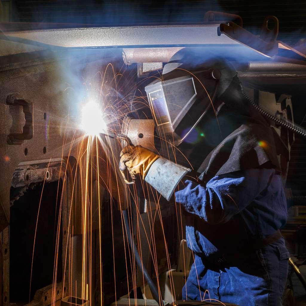
FCAW is a high-production process employed to weld a variety of ferrous materials, particularly in industries where the materials being joined are heavy-weight and thick. As with other arc welding processes, the heat of an electrical arc is used to melt and fuse two pieces of base metal with the addition of weld filler metal provided by a consumable welding electrode.
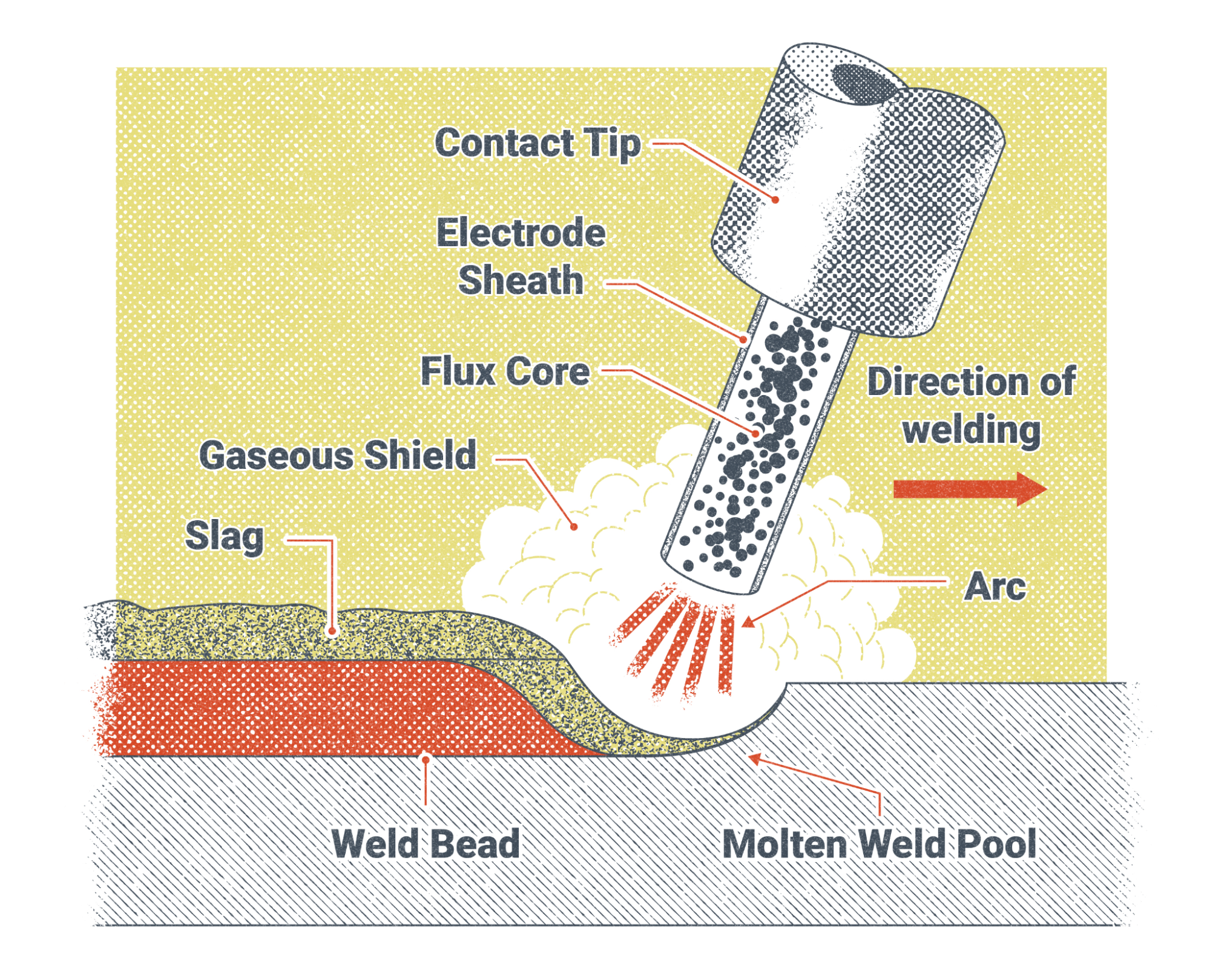
The most distinguishing characteristic of the FCAW process is the flux core electrode from which it gets its name. The electrode is hollow (referred to as a tubular electrode), with its exterior consisting of a metal sheath and its interior filled with powdered flux. The flux elements in FCAW are deoxidizing and denitrifying, shielding, and alloying, and they are also responsible for arc stabilization and slag formation. SMAW electrodes can do the same, but FCAW electrodes also come in the form of long continuous coils, ranging in size from just a few pounds to large 500 pound coils packaged in drums. They are available in a range of diameters from as small as 0.035 inch up to 0.125 inch. The larger diameter wires can deposit a large amount of weld metal in a short amount of time, while smaller diameter wires are more suitable for thinner materials and vertical or overhead welding.
The benefits of continuous wire electrodes, particularly in high-production environments, cannot be understated. The development of coated stick electrodes and SMAW greatly improved weld quality. However, the slow welding speed, downtime to change electrodes, and “stub loss” gave rise to a motivation to combine the advantages of SMAW with those of a continuous, mechanically fed electrode. FCAW is capable of producing welds with comparable or superior quality to those of the SMAW process but in much shorter times and with less welder training.
hese advantages are further buttressed by the fact that FCAW is considered a semiautomatic process: since the electrode is fed into the weld pool mechanically by a wire feeding unit, less operator skill is required as compared to SMAW, for which the electrode is fed into the weld pool manually. The mechanization of feeding the electrode also results in much faster travel speeds along the joint and much higher weld metal deposition rates as compared to SMAW. All other aspects of welding—electrode angle, electrode manipulation, and travel speed—are still under the direct control of the welder. Additionally, in manual processes, like SMAW and GTAW, the welder is in direct control of the arc length, but in FCAW and GMAW, the arc length is largely determined by settings at the power source and wire feeder. However, the welder must still maintain a constant electrical stickout, which is the length of wire electrode extending out of the tip of the welding gun. The further the gun is held from the work during welding, the longer the stickout. Electrical stickout greatly impacts shielding, welding current, and arc stability. Though FCAW is most commonly employed in this semiautomatic fashion, the process also lends itself well to mechanization or full automation.
That the FCAW electrode is continuous and mechanically fed is not the only characteristic that gives it advantages over other processes. For instance, GMAW also employs a continuous, mechanically fed wire electrode, but unlike FCAW, the electrode is solid, uncoated, and totally reliant on a shielding gas to protect the weld puddle from the atmosphere. This reliance on shielding gas makes GMAW unsuitable for outdoor use. In contrast, the shielding provided by the flux in FCAW electrodes has seen the process, particularly FCAW-S, gain wide outdoor use across a number of industries. Beyond providing shielding, the flux also contains deoxidizers and denitrifiers, which serve to soak up contaminants that would otherwise lead to weld defects. This reduces the amount of cleaning required on the base metal prior to welding. Alloying elements are also present in the flux, improving weld quality and allowing the electrode to be tailored to weld a variety of materials. The flux also produces a slag coating, which solidifies atop the weld metal; this layer of slag slows the cooling rate of the solidifying weld metal and protects it from atmospheric contamination as it cools. Other elements in the flux aid in arc starting and serve to stabilize the welding arc, improving weld quality and increasing operator appeal.
Though FCAW boasts many great advantages, the process is not without limitations. It is a dirty process, producing large amounts of welding fumes, especially with use of self-shielded electrodes. Not only can these fumes cause visibility issues, obscuring the welder’s view of the puddle, but they can become a health concern if welders don’t take care to properly ventilate the welding environment.
The layer of slag produced by the process also introduces a few special considerations. Firstly, the slag must be cleaned between each successive pass of a multi-pass weld, and even single-pass welds must have their slag removed to permit a visual inspection of the weld. This cleaning requirement limits the process’s ability to be fully automated. And secondly, as with any welding process that produces slag, FCAW has the possibility of slag inclusions—cavities within the weld caused by the metal solidifying around a pocket of slag. Slag inclusions are discussed in greater depth in Chapter 19.
Finally, FCAW is mostly limited to ferrous materials, including cast iron and stainless steel. Nickel-based alloys, such as Hastelloy and Inconel™, are the exception to FCAW’s general limitation to ferrous metals. Commonly welded non-ferrous metals like aluminum, titanium, copper, and copper alloys (brass, bronze, etc.) must be joined by another process.
Uses of FCAW in Industry Today
Although FCAW is limited to ferrous metals, it is used in various industries, as these metals, steel in particular, make up the majority of materials joined by arc welding in our present day. The process’s fast travel speeds, high weld metal deposition rates, and suitability for outdoor welding environments make FCAW extremely popular in what’s considered heavy industry: structural fabrication and construction, maritime, railroad, automotive, mining, and heavy equipment manufacturing industries. They all share a need for high-quality welds produced quickly and at an economical cost.
Another characteristic that ties these industries together is that they all employ a variety of steels. Later in this textbook, there will be a discussion of how the alloy content of steel, and the carbon content in particular, is an important determinant of how difficult it is to weld. FCAW can be successfully employed to weld a wide variety of carbon and low-alloy steels. Hardened and abrasion-resistant steels may also be readily welded with FCAW, provided the proper electrode and welding techniques are used. There are also FCAW electrodes for welding stainless steel and nickel alloys.
Attributions
- Figure 9.1: Roy Bearden performs flux cored arc welding on an M1 tank by Mark Cleghorn in the Public Domain; United States government work
- Figure 9.2: FCAW Weld Pool Diagram by Nicholas Malara, for WA Open ProfTech, © SBCTC, CC BY 4.0
This textbook, Welding Theory Fundamentals, has been edited by Cary Flanigan for use in the welding program at Clover Park Technical College from other openly licensed texts. A solid understanding of welding theory is essential for building the skills and confidence needed to excel in today’s welding industry. This resource has been thoughtfully developed with the technical college student in mind, offering clear, practical explanations of core welding concepts.
From the principles of heat and fusion to the behavior of metals and the science behind various welding processes, this textbook lays the theoretical groundwork for hands-on welding proficiency. Additional emphasis is placed on safety, joint design, and the relationship between welding variables and weld quality. Supporting content on material properties and welding codes enhances students’ readiness for real-world applications.
Whether you are new to welding or seeking to reinforce your foundational knowledge, this textbook is designed to align with the curriculum and goals of Clover Park Technical College’s welding program.
Summary
This chapter covered GMAW in depth. This welding process can be used with both ferrous and non-ferrous metals. The machine used is a CV power type machine, which can also be used for FCAW. Changing the wire feed speed, gas type, and voltage will change how the welding wire melts and becomes a weld. The balance of these different settings creates transfer modes, of which there are four basic types: spray transfer, pulsed spray transfer, short circuit, and globular. There are also different GMAW guns such as a spool gun or push-pull gun. GMAW can be used with inert or active gasses which created the slang terms MIG and MAG welding. A welder should be familiar with the internal components of the machine and be comfortable resolving wire jamming and changing out the wire spools.
Review Questions
- What are the different transfer modes for GMAW?
- What type of shielding gas is most common for GMAW?
- Can a welding machine set up for GMAW also be used for FCAW ?
- If #3 is a yes, what equipment do you need to change out? If #3 is no, why not?
- What polarity is used for welding aluminum with the GMA process?
- What is GMAW-P?
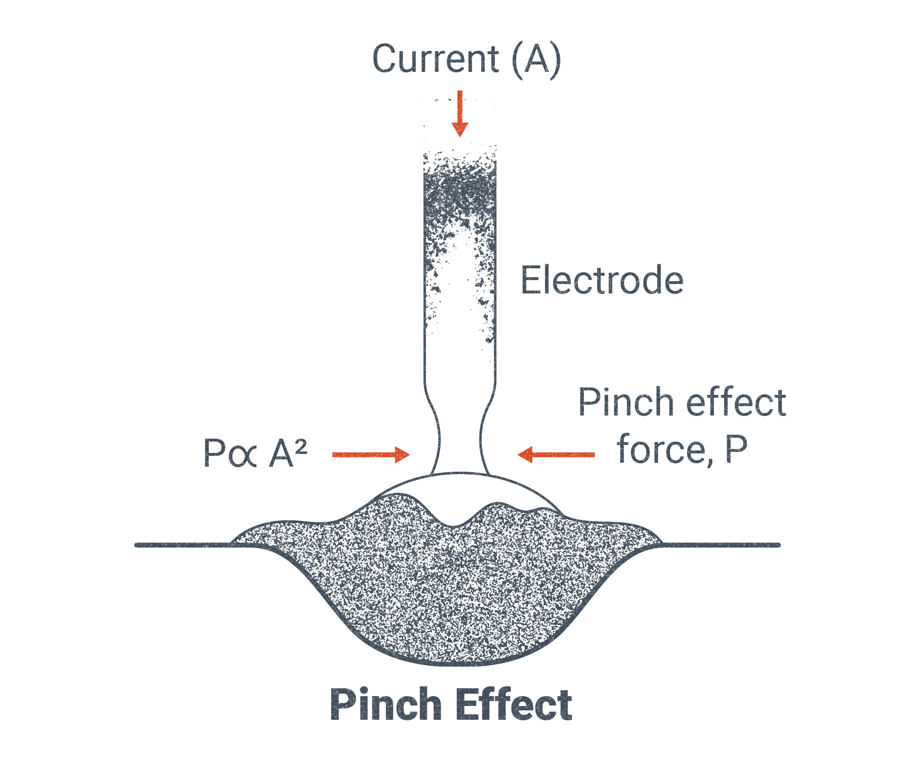
- Describe pinch force effect.
- Explain the concerns of using globular transfer mode.
- Are there any recommended oscillation patterns when MIG welding stainless steel joints thicker than 0.25 inches?
- Are there different welding guns you learned about in Chapter 9 that would be appropriate for welding aluminum with GMAW?
Armao, F. (2016, July 22). Aluminum Workshop: What are the advantages of AC in aluminum GMAW? The Welder, July/August 2016. https://www.thefabricator.com/thewelder/article/aluminumwelding/aluminum-what-are-the-advantages-of-ac-in-aluminum-gmaw
Arnao, F. (2023, January). Aluminum Workshop: Aluminum flux-cored wire welding with FCAW/SAW. The Fabricator. https://www.thefabricator.com/thewelder/article/aluminumwelding/aluminum-workshop-aluminum-flux-cored-wire-welding-with-fcawsaw
AlcoTec. (2023, June). A short history of welding aluminum. AlcoTec. http://www.alcotec.com/us/en/education/knowledge/qa/A-short-history-of-welding-aluminum.cfm
Beaton, R., Lozada, A. L., Zigh, A., Durbin, S., & Lindgren, E. Experiments on ignition of zirconium-alloy in prototypical pressurized water reactor fuel assemblies in a spent fuel pool with complete loss of coolant. United States Nuclear Regulatory Commission. ML14335A547. https://www.nrc.gov/docs/ML1433/ML14335A547.pdf
Elmer, J. W., & Gibbs, G. (2018, December). The effect of gas impurities on the composition of wire arc additive manufactured metal components. LLNL-JRNL-763961. United States Department of Energy, Lawrence Livermore National Laboratory.
Grill, J. (2023, May). How to MIG weld aluminum (with chart). Weld Guru. https://weldguru.com/mig-welding-aluminum/
NASA. (2017). SR-71 Blackbird. NASAfacts, FS-2008-6-030-DFRC. Dryden Flight Research Center, National Aeronautics and Space Administration. https://www.nasa.gov/wp-content/uploads/2021/09/495839main_fs-030_sr-71.pdf
(OSHA) Occupational Safety and Health Administration. (n.d.). Beryllium - Overview. U.S. Department of Labor. https://www.osha.gov/beryllium
Pittsburgh Mineral & Environmental Technology, Inc. (PMET). (2022, November). A short history of welding aluminum. LinkedIn. https://www.linkedin.com/pulse/short-history-welding-aluminum-pmet-pittsburg-mining-environmenta/?trk=pulse-article
Pittsburgh Mineral & Environmental Technology, Inc. (PMET). (2022, December). History of welding aluminum. PMET. https://www.pmet-inc.com/history-of-welding-aluminum/
Powell, C. (2023, June). Solid phase processing demonstration facility, shaping the future of materials. United States Department of Energy, Pacific Northwest National Laboratory. https://www.pnnl.gov/solid-phase-processing-demonstration-facility
Shyam, A., & Haynes, J. A. (2018, June). ORNL-developed alloy promises better fuel economy. United States Department of Energy, Oak Ridge National Laboratory. https://www.ornl.gov/blog/ornl-developed-alloy-promises-better-fuel-economy
Talbert, R., & Keeton, R. D. (1996). Steelworker, Volume 1, NAVEDTRA-14250. United States Navy, Naval Education and Training Professional Development and Technology Center. https://archive.org/details/USNavyCourseAviationMaintenanceRatingsNAVEDTRA14022/US%20Navy%20course%20-%20Steelworker%2C%20Volume%201%20NAVEDTRA%2014250/
U.S. Army. (1993, May). Operator’s circular welding theory and application: Reporting errors and recommending improvements. TC 9-237. https://armypubs.army.mil/epubs/DR_pubs/DR_a/pdf/web/tc9_237.pdf
United States Department of Energy, Fermilab, Applied Physics and Superconducting Technology Directorate. (2023, June). Machine shop department. https://td.fnal.gov/machine-shop/
United States Department of Energy, Oak Ridge National Laboratory. (2023, June). Functionally and geometrically ordered Ti armor, design and processing of Ti composite armors. Computational Engineering and Energy Science Research. https://energy.ornl.gov/armor/materials/materials.cgi?nav=1
United States Department of Energy, Pacific Northwest National Laboratory. (2015, May). Out with heavy metal. https://www.pnnl.gov/news/release.aspx?id=4200
United States Department of Transportation, Federal Highway Administration. (2015, August). Gravel roads construction & maintenance guide. FHWA-OTS-15-0002.
United States Environmental Protection Agency. (2023, June). Aluminum forming effluent guidelines. https://www.epa.gov/eg/aluminum-forming-effluent-guidelines
United States National Aeronautics and Space Administration. (2014, February). NASA Armstrong fact sheet: SR-71 Blackbird. https://www.nasa.gov/centers/armstrong/news/FactSheets/FS-030-DFRC.html
Weiss, D., Gwyn, M., & Sturgill, K. (2020, January). Recommendations for welding aluminum castings. The American Foundry Society. https://www.moderncasting.com/articles/2020/01/07/recommendations-welding-aluminum-castings
GMAW Modes of Transfer
At the beginning of this chapter, you read a reference to how there are “modes” in GMAW welding. But what does that mean, and what distinguishes the modes?
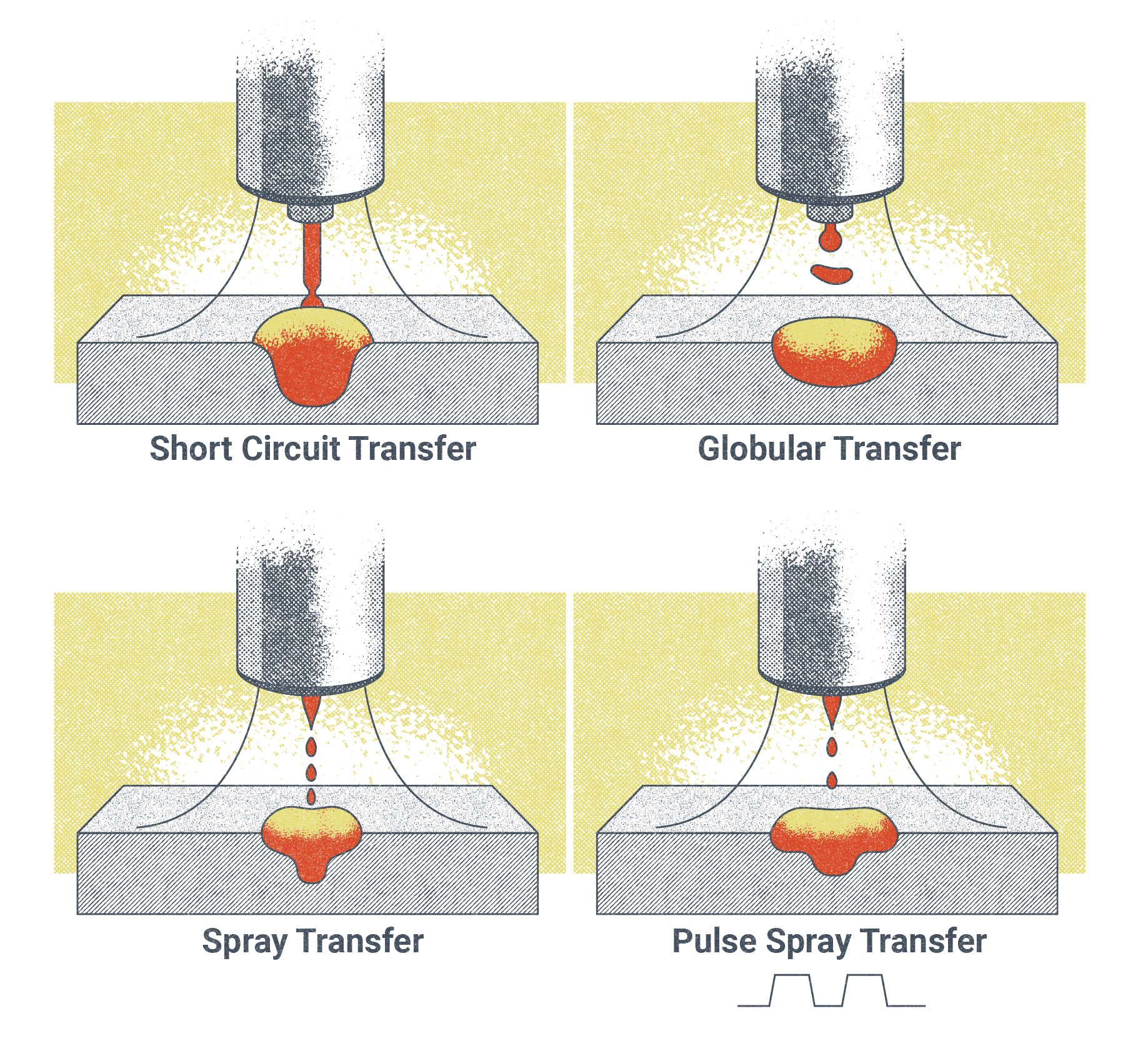
We have already discussed how MIG and MAG welding offer versatility. That is because the operator can easily interchange the relationship between wire and heat. This, along with the ability to change wire types, sizes, and shielding gasses, creates different behavioral changes in how the electrode wire melts and gets transferred to the base metal. These are referred to as transfer modes, and they are the key to the GMAW process’s diversity and utility. In GMAW, there are four transfer modes.
Spray Transfer Mode
Spray transfer refers to the behavior in which the wire from the welding machine melts at the tip and deposits into the joint so as to create fine droplets that are equal to or less than the diameter of the electrode wire being used. For this to occur, the machine must reach the transition current, which is the minimum current setting for the welding machine to transition from globular transfer and into spray transfer. It is important to note that the transition current is not universal but rather dependent on variables such as electrical stickout, electrode type, and electrode wire diameter.
For example, a 0.035-inch diameter wire of the ER-70S-6 classification may reach its transition current into spray transfer when the welder is set to 24V–32V and 350–580 inches per minute (IPM).
As the consumable wire electrode interacts with the shielding gas and is melted by the electrical arc it results in what’s called pinch force. Pinch force along with surface tension acts as a squeeze or pinch on the end of the consumable wire electrode, allowing a droplet to break free of the tip of the wire and be distributed onto the base metal or joint. For spray transfer, pinch force on the electrode is increased to the point that the molten metal produces a fine conical spray, depositing an even and virtually spatter-free weld with a deeper penetration than the other transfer modes.
For this transfer mode it is important to select the appropriate shielding gas and welder settings in order for a fine cone-like spray to occur. For ferrous applications, a shielding gas of at least 80% argon must be used. For non-ferrous metals such as aluminum alloys a shielding gas of 100% argon is recommended.
Spray transfer is best suited for the flat (1G/1F) and horizontal (2G/2F) welding positions.
Pulsed Spray Transfer Mode
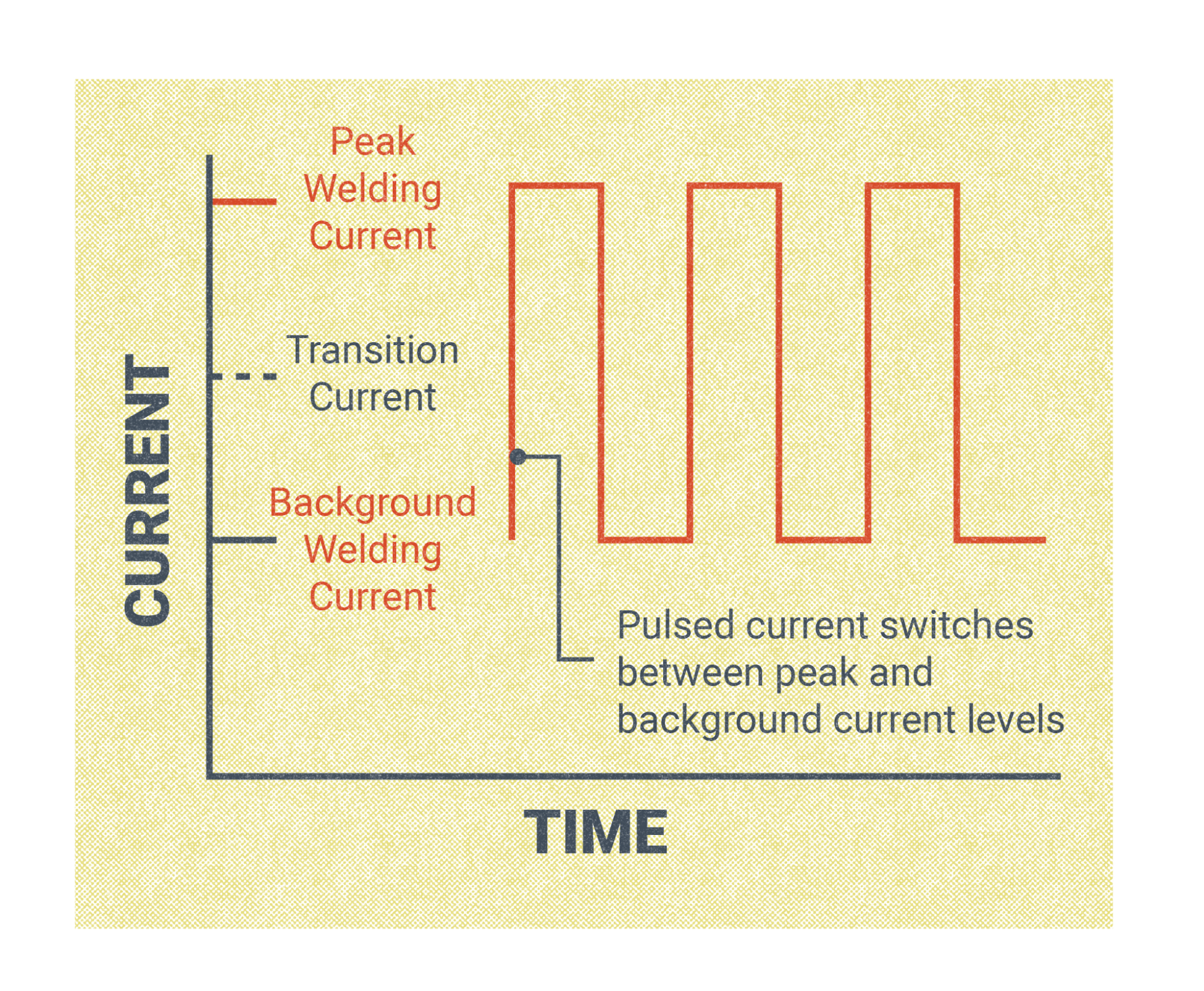
Pulsed spray transfer mode(also called GMAW-P), offers welders the ability to weld spray transfer out of position, such as overhead, and to utilize thicker wire electrodes than traditional spray transfer. It also requires lower heat input, offers 98% electrode efficiency, and can be used to create a consistent root on open joints without the need for a backing bar.
GMAW-P is not available on all MIG/MAG wire feed machines. When it is selected, pulsed spray transfer allows the current to toggle between a preset high current and down to a preset low current. Just like standard spray transfer, when GMAW-P is at the high curren, a molten droplet forms at the end of the electrode and is then pinched from the tip and deposited as a fine cone-shaped spray to the joint. But unlike regular spray transfer, the welder will then revert to a low current—during which no metal transfer occurs—before cycling back to the high current. This toggling between the two current settings occurs rapidly and as much as several hundred times a second. The return to a low current drops the overall heat input into the workpiece, allowing spray transfer to be used with thinner base metals and lessening the overall heat distortion. The frequency of this pulsing from high to low increases as the wire feed speed increases.
Short Circuit Transfer
Short circuit transfer mode, or GMAW-S, is one of the most common wire-feeding processes. Like spray transfer, this process uses a solid or hard wire, is impacted by pinch force, and can support a multitude of different wire electrode types and thicknesses. However, there are distinguishing features of the two modes of transfer and reasons for selecting one versus the other.
Short circuit transfer occurs when the welding current is less than 200 amps for a wire diameter of 0.045-inches or less. What is unique to the short circuit transfer mode is that metal is not transferred across the arc—rather, the weld puddle freezes quickly in between these short circuits before the arc is reignited again and the wire electrode makes contact with the puddle once more.This behavior makes short circuit transfer ideal for situations where heat input is a concern and for welding areas with wide gaping or poor fit-up. A welder may also find this welding method more ideal when welding in the 3F/3G and 4F/4G positions due to its rapid freezing ability.
While this transfer mode offers more accessibility and is generally considered easier to learn, it has disadvantages. GMAW-S has a lower electrode efficiency than spray transfer, at about 93%. While short circuit transfer allows for an increase in travel speed, it also increases the potential for spatter and longer post-weld cleanup time. Additionally, welders choosing GMAW-S need to be conscientious of the increased risk of incomplete fusion.
The shielding gas used with short circuit transfer can vary and depends on the overall needs of the weld. Pure (100%) CO2 is used in scenarios where a deeper penetration may be desired, but the operator may sacrifice overall consistency and bead contour. A more common choice is a 75% argon and 25% CO2 mixture for arc stability, faster travel speeds, and lower spatter.
Globular Transfer
Globular transfer mode is sometimes referred to as the accident that occurs when trying to change from spray transfer to short circuit, insinuating that there isn’t an intentional reason for a welder to choose this mode when using GMAW. While its uses are limited, there are very real reasons a procedure may call for its use.
Globular transfer mode is named such because of how the wire melts off the end of the consumable wire: it forms a large glob-like droplet that is 2–3 times the size of the wire diameter. The globs fall off very erratically and aggressively, often resulting in an inconsistent bead appearance and heavy spatter. While the behavior in which these droplets cast off is very unpredictable, they can be managed with a variety of techniques or gas choices. For example, a welder may choose to lower their arc voltage, effectively producing a shorter arc. Additionally, this process can be used in congruence with a shielding gas containing a higher percentage of an inert or nonreactive gas, such as argon, to create more arc stability and a greater chance of the globs reaching the weld pool.
When used with 100% CO2, globular transfer produces excellent penetration, but the chances of an unpredictable arc and spatter also increases. To offset this, lowering the weld current rather than the voltage is recommended. The effects on the weld in this scenario would be a weld puddle that is more fluid, deeper, and essentially lower than the base metal. This technique is called a buried arc. This can create undercut (a weld discontinuity), but it also contains more of the spatter within the pool.
There are other disadvantages of globular transfer. As spatter increases, so does post-weld clean up, which costs time and money. The more spatter produced also decreases electrode efficiency. Globular transfer has the lowest electrode efficiency of all the transfer modes at only 85–89%. Also, globular transfer is not recommended for welding in vertical and overhead positions.
Despite the challenges and potential weld discontinuities of using globular transfer, this mode produces a deeper penetration than short circuit transfer and allows for higher WFS.
And if the cost of using an inert gas is an issue but concerns about post-weld clean-up time is not a factor, globular transfer may be a solution for thicker joints requiring a deeper penetration than what is offered by short circuit transfer.
In general, most GMAW procedures will call for spray transfer or short circuit transfer versus globular.
GMAW Welding Fundamentals for Ferrous Metals
Ferrous metals are metals that contain the element iron and include carbon steel, cast iron, stainless steel, wrought iron, and mild steel. These base metals can all be welded using GMAW or GMAW-P.
Each of these metals requires its own care and consideration on shielding gas, heat input, post-heating, and cooling. For example, mild steel is very common and can be used with a shielding gas mixture composed of 75% argon and 25% CO2. However, while also common, stainless steel would work best with either a richer argon mix or a helium mix gas. Both materials would require the use of V groove drive rollers and steel coiled gun liners, and they can be purchased in the same diameter.
GMAW welding produces no slag crust on the top of the weld and therefore can be pushed or pulled depending on the desired outcome. A pulling or dragging motion of the weld can produce deeper penetration but leave the weld face leaner and more protruded. In contrast, pushing the weld puddle may leave the weld with a smoother weld bead contour but have slightly shallower weld penetration. The choice to push or pull often depends on the base metal and how thick it is.
With stainless steel MIG welding, it is recommended to weld in a slight up-and-down zigzag motion in the flat and vertical positions when the material is thicker than 0.25 inches. If the base metal is thinner than 0.25 inches, then angle the zigzag motion at a diagonal.
For mild steel joints, a welder may choose from an array of oscillations and weave patterns depending on the position and thickness of the metal.
A T-joint in the overhead position may call for the welder to create a small J-shaped pattern. This would involve favoring the top plate but then sweeping through the bottom quickly to help offset the pull of gravity on the weld. Alternatively, a series of up-and-down zigzags or even a steady hand with a pull position may prove useful.
The ratio of the wire feed speed to the voltage when welding ferrous metals depends on the diameter of the wire, type of transfer mode, type of metal, weld position, and gas mixture.
| Thickness (ga.) | Wire Diameter (Inch) | Wire Feed Speed (IPM) | Current (Amps) | Voltage |
|---|---|---|---|---|
| 24 | 0.023 | 140-170 | 40-50 | 14-15 |
| 24 | 0.030 | 110-120 | 45-50 | 13-14 |
| 20 | 0.030 | 125-135 | 55-60 | 13-14 |
| 20 | 0.035 | 105-115 | 50-60 | 15-16 |
| 18 | 0.035 | 140-160 | 70-80 | 16-17 |
| 16 | 0.035 | 180-220 | 90-110 | 17-18 |
| 16 | 0.045 | 90-110 | 90-110 | 17-18 |
| 14 | 0.035 | 240-260 | 120-130 | 17.5-18 |
| 10 | 0.035 | 280-300 | 140-150 | 18-19 |
| 10 | 0.045 | 140-150 | 140-150 | 18-19 |
| 3/16 | 0.035 | 320-340 | 160-170 | 18.5-19.5 |
| 3/16 | 0.045 | 160-175 | 160-170 | 18.5-19.5 |
| Thickness (ga.) | Wire Diameter (Inch) | Wire Feed Speed (IPM) | Current (Amps) | Voltage |
|---|---|---|---|---|
| 18 | 0.030 | 130-160 | 30-40 | 15-16.5 |
| 18 | 0.035 | 105-115 | 50-60 | 18-18.5 |
| 16 | 0.035 | 140-160 | 70-80 | 18-19 |
| 14 | 0.035 | 180-220 | 90-110 | 18.5-19 |
| 14 | 0.045 | 90-110 | 90-110 | 18.5-19 |
| 10 | 0.035 | 240-260 | 120-130 | 19-20 |
| 10 | 0.045 | 120-130 | 120-130 | 19-20 |
| 3/16 | 0.035 | 280-300 | 140-150 | 19-20 |
| 3/16 | 0.045 | 140-150 | 140-150 | 19-20 |
GMAW Welding Fundamentals for Non-Ferrous Metals
Welding non-ferrous metals (metals that do not contain iron) with GMAW typically runs on DCEP and often utilizes pulsed spray transfer for greater heat control. Because some weld wire, such as aluminum, is a soft material, the risk of jamming the machine increases. To avoid this, it’s recommended to keep the GMAW gun whip less than 6 feet in length or to use a push-pull gun or spool gun.
The liner that runs along the inside of the MIG whip must be plastic when welding non-ferrous materials like aluminum. V groove rollers must also be used, and with an increased tension between them than is needed for ferrous materials. Drive roller tension should be 1 or less for a push-pull gun system used on aluminum. Consult the manufacturer of your machine or the manual provided by them for their recommendations on replacing the liner and adjusting the tension for the wire type and thickness.
When welding non-ferrous metals, 100% argon is very commonly selected as the shielding gas, but a mixture may also be used.
Attributions
- Figure 10.15: Wire transfer mode types by Nicholas Malara, for WA Open ProfTech, © SBCTC, CC BY 4.0
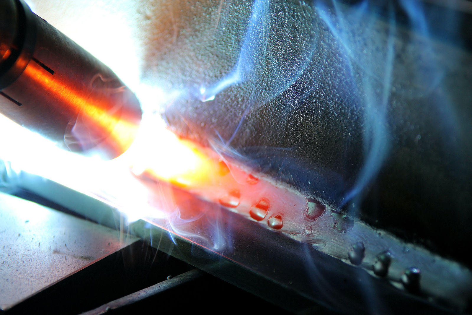
- Figure 10.16: Schweißen2 by Dako99 is released under CC BY-SA 3.0
- Figure 10.17: Pinch Force by Nicholas Malara, for WA Open ProfTech, © SBCTC, CC BY 4.0
- Figure 10.18: Pulse Table by Nicholas Malara, for WA Open ProfTech, © SBCTC, CC BY 4.0
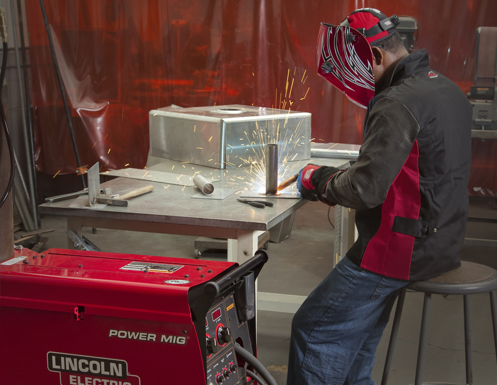
- Figure 10.19: GMAW application by Mgschuler is released under CC BY 3.0
