Chapter 16: Blueprints and Welding Symbols
Overview
Blueprints are the most effective means of communicating fabrication requirements from the engineer to the fabricator. They are so named for the now-obsolete process of impregnating paper with a light sensitive chemical—ammonium ferric acid—to reproduce plans and drawings, and which turned the paper blue (Wikipedia, 2023).
Welding symbols are a standardized system developed by the American Welding Society (AWS). To a layperson the symbols may not mean much, but with a little knowledge they become an incredibly effective tool for communicating welding requirements for any project.
Print and weld symbol interpretation are broad topics with many conventions, and fully exploring the topics would warrant its own book. However, this chapter will equip the reader with enough fundamental knowledge to interpret most blueprints they will encounter.
Objectives
After completing this chapter students will be able to:
- Interpret blueprints
- Interpret welding symbols
- Identify nondestructive examination (NDE) symbols
Key Terms
- Baseline dimensioning
- Continuous weld
- Conventional dimensioning
- Intermittent weld
- Line weight
- Location dimensions
- Orthographic projection
- Size dimensions
- Welding symbol
Attributions
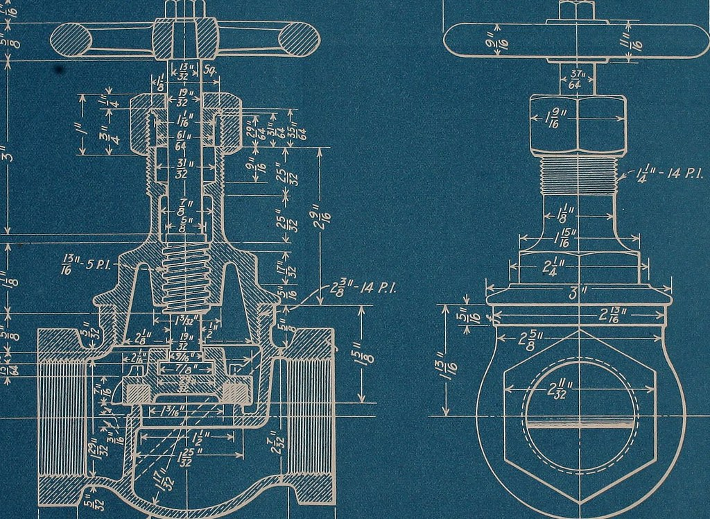
- Chapter opening image: Image from page 70 of “Blueprint reading; a practical manual of instruction in blueprint reading through the analysis of typical plates with reference to mechanical drawing conventions and methods, the laws of projection, etc” (1919) by Internet Archive Book Images in the Public Domain; Published 1919.
