10.1 History of GMAW
Stephanie Oostman
Development of GMAW
While electric arc welding started in the 1800s, gas metal arc welding (GMAW) didn’t make it onto the welding scene until the 1920s when General Electric designed it under similar constructs of gas tungsten arc welding (see Chapter 11). It was an early version based on the concept of using a consumable, continuously fed electrode operating on a constant voltage (CV) circuit. It wasn’t until the Battelle Memorial Institute picked up the development of the process in 1948 that we began to see the wire-feeding process that we are more familiar with today. GMAW has continuously had advancements and improvements since its inception.
GMAW was used for exclusively joining non-ferrous metals until 1953, when the use of carbon dioxide (CO2) was introduced as an atmospheric shielding gas. This change in gas mixtures allowed for both ferrous and non-ferrous welding applications. However, the only transfer mode—which we will explore in detail later in this chapter—developed at the time was spray transfer, which used a large-diameter electrode wire. The addition of CO2 to the shielding gas in steel applications meant higher heat, which in turn discouraged some welders from using it and limited the versatility the process now holds in the present day.
Then in 1958 to 1959, short circuit transfer mode was developed, which allowed for a smaller diameter electrode wire to be utilized. It took a more advanced power supply but required lower heat levels, making it popular with the growing sheet metal industries at the time. Its smaller wire is also how this process came to be called micro-wire and the behavior of short circuit transfer mode earned the term dip transfer.
More advancements were made in the 1960s and 1970s to the original spray transfer process, introducing what is called spray transfer pulse, which assisted in lowering overall heavy heat input into the work pieces, among other benefits.
GMAW and other welding processes are continuously updated as equipment manufacturers and technology advance. This is by no means a fully encompassing history of GMAW, and the welding technology will adapt further in our lifetimes.
Basics of the Process
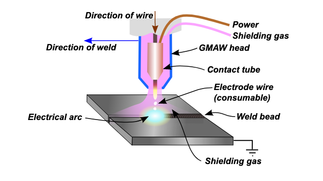
GMAW is what is referred to as a semiautomatic process. because although the welder controls the gun and the travel speed, travel angle, work angle, and electrical stickout (the length the electrode wire protrudes from the end of the nozzle), they preset the wire-feed speed (WFS), current, voltage, and gas flow rate (typically in cubic feet per hour) on the welding machine before starting. GMAW could be set up as a fully automatic welding process if used in conjunction with a computer numerical control or robotic type system.
The GMAW process uses a solid wire electrode that is continuously heated and fed from the welding machine and into the weld pool. The wire runs through the gun conduit cable, sometimes referred to as a whip, which contains a liner sheath inside, and runs through a contact tip and onto the surface to be welded. The shielding gas comes out of holes along the contact tip, fills the nozzle, and protects the wire and molten weld puddle directly in front of the arc.
The process is incredibly versatile allowing for the welding of both ferrous and non-ferrous metals and for the use of different shielding gasses. Both inert gas is called metal inert gas (MIG), and reactive gasses are metal active gas (MAG). The thickness of the electrode wires range from about 0.023 inches to 0.125 inches in diameter, making GMAW suitable for a wide range of metal thicknesses and needs.
GMAW typically uses direct current electrode positive (DCEP), commonly referred to as reverse polarity. DCEP is ideal for GMAW because promotes deeper penetration of the weld, the least amount of spatter, and more predictable metal transfer, all while allowing for the best cleaning of the oxide layer that is found on most metals.
A CV power source, such as a transformer-rectifier or inverter, is used in this process. CV machines maintain the voltage set at the panel throughout welding, even as the welder changes the electrical stickout. Changing the stickout distance does increase or decrease the resistance in the wire, and therefore, the machine will adjust the current appropriately. Because the wire is continuously fed, the arc length does not change, and therefore the voltage will remain the same. Section 10.2 goes into more detail about setting up the welding machine for use.
Uses of GMAW in Industry Today
Today, GMAW is used all over the world in a large array of applications. It is commonly used in the sheet metal industry, and by extension, the automobile industry, as well as for pipe fitting, robotic welding, railway, construction, and manufacturing. Because the equipment for GMAW isn’t as portable as other processes, welders utilizing this process will more often than not find themselves working in fabrication shops. This process is also popular amongst hobbyist welders and artists due to its general ease of use and the low maintenance of the equipment. The gas type, filler metal, base metal, and transfer mode all play a factor in what can be welded and how to weld it with the GMAW process.
Attributions
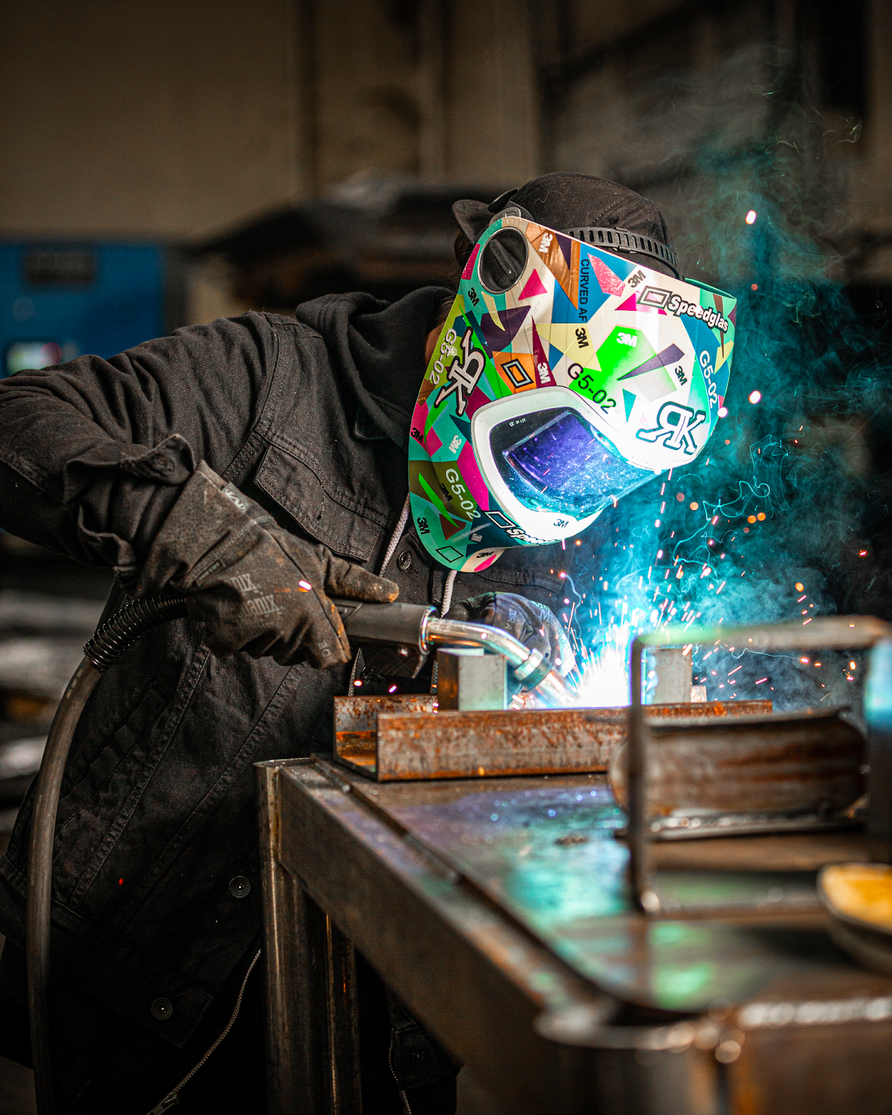
- Figure 10.1: RK WL GMAW by Weldscientist is released under CC BY-SA 4.0
- Figure 10.2: GMAW diagram en by Curkuma Putz is released under CC BY-SA 3.0
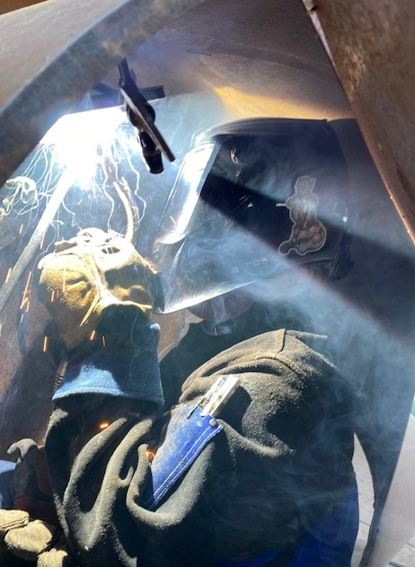
- Figure 10.3: A MIG welder at work by Stephanie Oostman, for WA Open ProfTech, © SBCTC, CC BY 4.0
Wire-feed speed is a measure of how fast the wire electrode is being fed out from the spool by the feed unit and is measured in inches per minute.
Metal inert gas welding is an obsolete name for gas metal arc welding, as this process no longer uses only inert gasses. However, many welders still use this name when referring to GMAW.
Metal Active Gas welding
