11.2 GTAW Equipment and Setup
Karl Fulton
Components
The equipment needed for GTAW include a welding power source, shielding gas, regulator and flow meter, electrode holder (known as a torch), tungsten electrode, filler rods, foot pedal or handheld power control, water cooler (when required), and personal protective equipment (PPE).
Welding Power Source
Most welding machines are capable of GTAW; the machine must be a constant current power source.
Some features on a power source built for GTAW include:
- Capabilities to run on direct current electrode positive (DCEP) or direct current electrode negative (DCEN).
- Alternating current (AC) functionality, which is often used to weld aluminum and magnesium. Some machines will give the operator the ability to adjust the balance of the AC wave and even control the shape of the wave.
- A solenoid valve that controls shielding gas flow and cooling water (if water cooler is attached).
- A foot pedal or handheld remote control that gives the operator the ability to not only turn on and off the flow of gas and current but also to increase or decrease the current while welding. Some machines will have a pre-flow to make sure the arc is protected from the beginning. Post-flow is used once you terminate the weld: the shielding gas continues to flow for a set duration of time to protect the weld as it cools. You will not want to move the torch at all during this time or lift your hood.
- The ability to run at a high frequency, allowing the operator to start an arc without touching the base metal.
Direct Current
There are two modes for direct current: DCEP, which is also known as reverse polarity, and DCEN, which is known as straight polarity. When the machine is set to straight polarity, the electrons flow from the electrode to the work in a way that directs the heat on your workpiece and not your electrode in a 70/30 split. This means 70% of the heat being created is on the work, and 30% is on the electrode. This is the most common way to set up a GTAW machine because it minimizes the wear and tear on electrodes.
When the welding machine is set up for reverse polarity, the electrons flow from the work to the electrode in a way that puts 70% of the heat on your electrode and 30% of the heat on the workpiece. When you have a non-consumable electrode—as you do with GTAW—this can be a detrimental process. However, there are benefits to using this polarity, because as the electrons flow up from the workpiece, positively charged ions strike the metal, breaking up the oxides on the surface of your work, which is a wonderful cleaning action. Also, setting the machine up this way will give you a very wide, shallow puddle. A fun thing to practice once or twice is to get a very thin sheet of aluminum and try to weld it with reverse polarity. Using a thicker tungsten is recommended, and even then you will notice it takes a lot of wear and tear.
Alternating Current
Alternating current continuously switches from DCEP to DCEN at 60 Hz, making this switch 60 times per second. The purpose of using AC while employing GTAW is to take advantage of the benefits of straight and reverse polarities at the same time. The advantages are extremely useful when welding aluminum, as you can break up the oxide on the surface and direct enough heat to the workpiece to weld.
There are three main factors to consider when using AC for welding: balance, frequency, and waveform. Not all machines will have the ability to manipulate all of these factors, though.
Balance gives you the ability to favor DCEP or DCEN. If your machine is set to 75/25 in favor of DCEN, the arc will be on DCEN for 75% of the time. Imagine 0.1 of a second of welding drawn with a 50/50 AC wave—positive on top, negative on the bottom, and 0 in the middle. This would result in six equal humps on both sides. The wave will stay on the negative side of the 0 three times as long as on the positive side. This would give you more penetration and less cleaning. But set the machine to 25/75 favoring DCEP and the wave would stay on the positive side of 0 for longer. This would give the arc more cleaning action and less penetration. It would also put much more heat on your tungsten.
The frequency setting on a welding power source affects how often the arc switches from DCEP to DCEN per second. Not all machines have this feature, and if they do the ability for machines to adjust the frequency will vary from as low as 20 Hz to as high as 350 Hz. At lower frequencies the arc cone is wider, and at higher frequencies the arc cone will be tighter, which can help to get into tight corners. If you are working with a machine with the ability to adjust frequency settings, it is highly recommended that you experiment with both extremes. However, a great generic setting for everyday welding is 110 Hz.
Note that high frequency is a separate function from your frequency adjustment. This function is intended to jump the gap between your tungsten and work to initiate your arc without contaminating your tungsten. It is also meant to maintain a stable arc during AC welding.
AC Waveforms
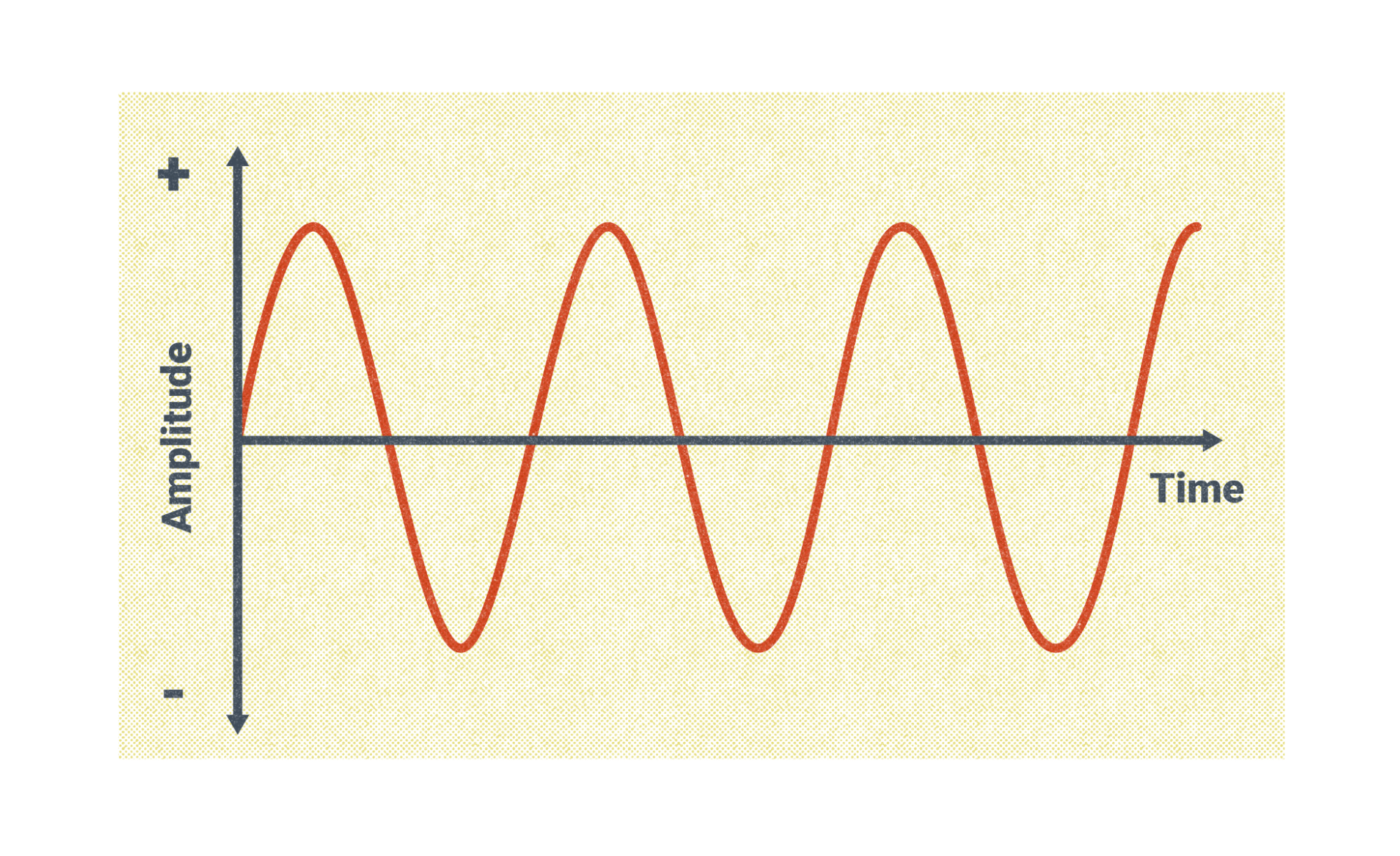
The original AC wave for GTAW was a sine wave. For a brief second, the sine wave passes through zero, and this can cause the arc to break or stutter. This produces a smooth arc that is good for welding but does require continuous high frequency to maintain the arc stability. By adding high frequency, the amount of time the arc is at zero is reduced to almost nothing.
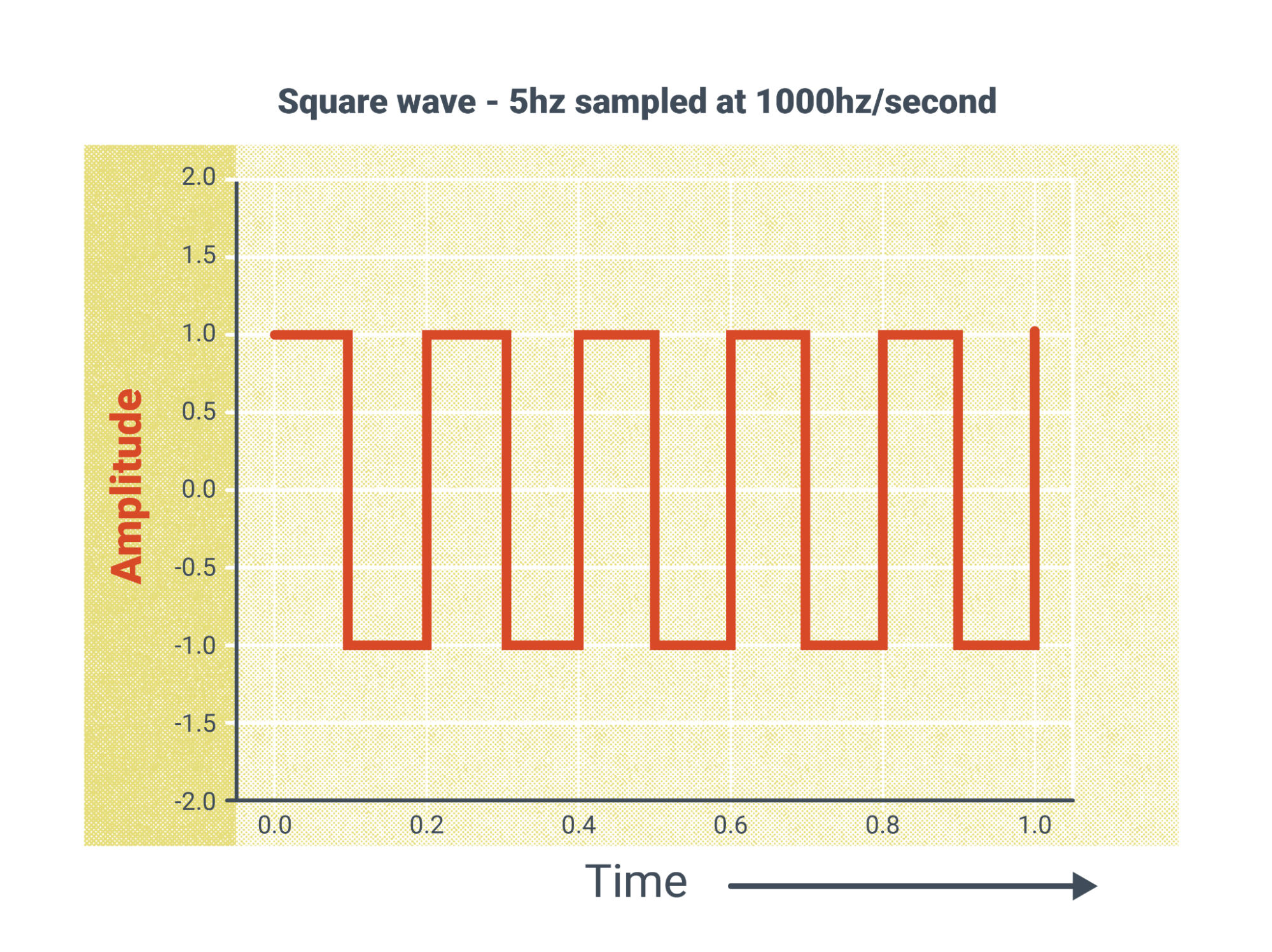
With the technology of inverter machines, the square wave was developed. Square wave switches instantaneously from reverse to straight polarity without spending any time at zero amperage. This removes the need for continuous high frequency and increases the heat input, allowing for faster travel speeds.
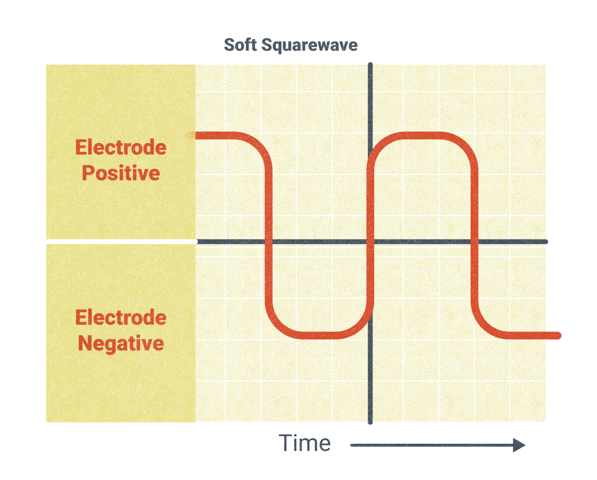
A soft square wave is a mix between the sine wave and the square wave, bringing the benefits of both. This is a good standard waveform for most AC welding.
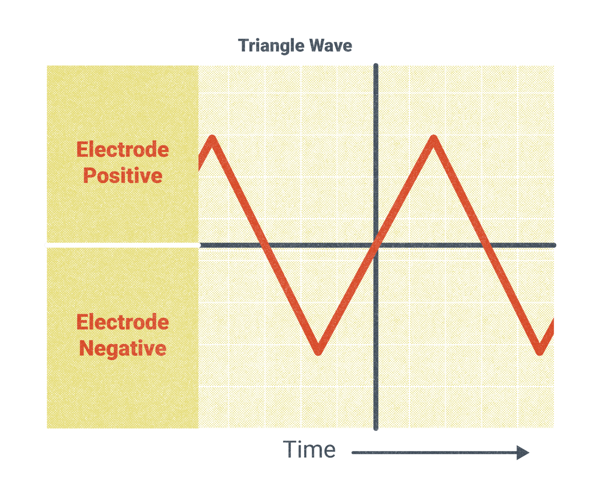
Finally, a triangle wave is used for reducing the heat on the base metal. This is a great waveform for working on thin materials to reduce distortion.
Torches
The torch is a critical tool in GTAW. They are designed to conduct the welding current and carry the inert gas to the weld zone. Torches are cooled by either air or water. Air-cooled touches are typically used for lighter gauge materials requiring less amperage. Water-cooled torches will typically have an amperage rating of over 200 amps. Water is pumped in from a cooler to cool the torch, and as it travels back it cools the lead as well. It’s very important to maintain the water in the cooler to prevent overheating. See the owner’s manual on the machine you use for details.
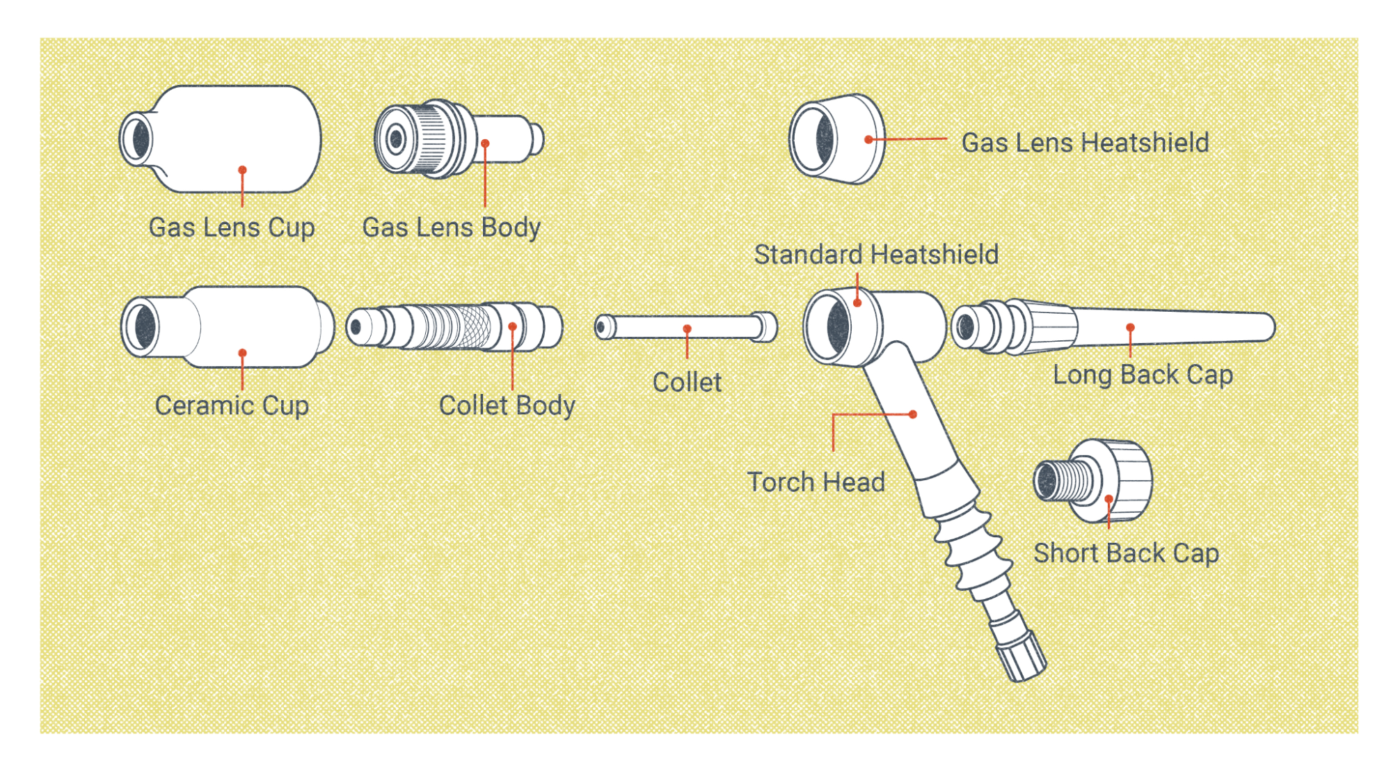
Most GTAW torches are going to be relatively the same, though they do come in a variation of sizes. Let’s cover the basic parts of the torch and what they do.
- Backing cap: This pushes the collet forward and caps the back of the torch. The interior of this cap is hollow to allow room for the excess tungsten.
- O-ring: The O-ring seals the backing cap to the torch body to ensure there is no gas leakage and a vacuum is not created, which would pull in the atmosphere to the weld zone.
- Electrode: Tungsten electrodes come in a variety of sizes and alloys. This will be the most commonly altered, replaced, or sharpened piece of your torch. If at any time the electrode becomes contaminated, you should address it immediately before continuing with welding.
- Collet: As the backing cap is tightened the collet is pushed forward, locking the tungsten electrode in place.
- Torch head/body: The whip for your gas, current, and water (if water-cooled) come together at the handle. The back cap, electrode, and collet are secured on the back while the collet body and nozzle go on the front of the torch body.
- Collet body or gas lens body: The collet body is attached to the front of the torch body. It’s important to make sure you tighten this piece before securing the backing cap to avoid creating a vacuum in the torch, which would lead to contamination in the weld. Gas lenses are an alternative that can be used in place of this part—they are diffusers that create a laminar flow of gas. Their advantage is you get a more even gas coverage with less likelihood of contamination. This also enables you to extend your tungsten slightly farther out of your nozzle/cup.
- Nozzle/cup: Torch nozzles direct the argon or helium shielding gas to the area in which you are welding. They come in an assortment of sizes. Their numbers represent one-sixteenth of the exit diameter. For instance, a number 5 nozzle has an exit diameter of five sixteenths (0.3125) of an inch. A good rule of thumb for how far your electrode can stick out is to make it equal to your exit diameter.
Regulators and Flow Meters
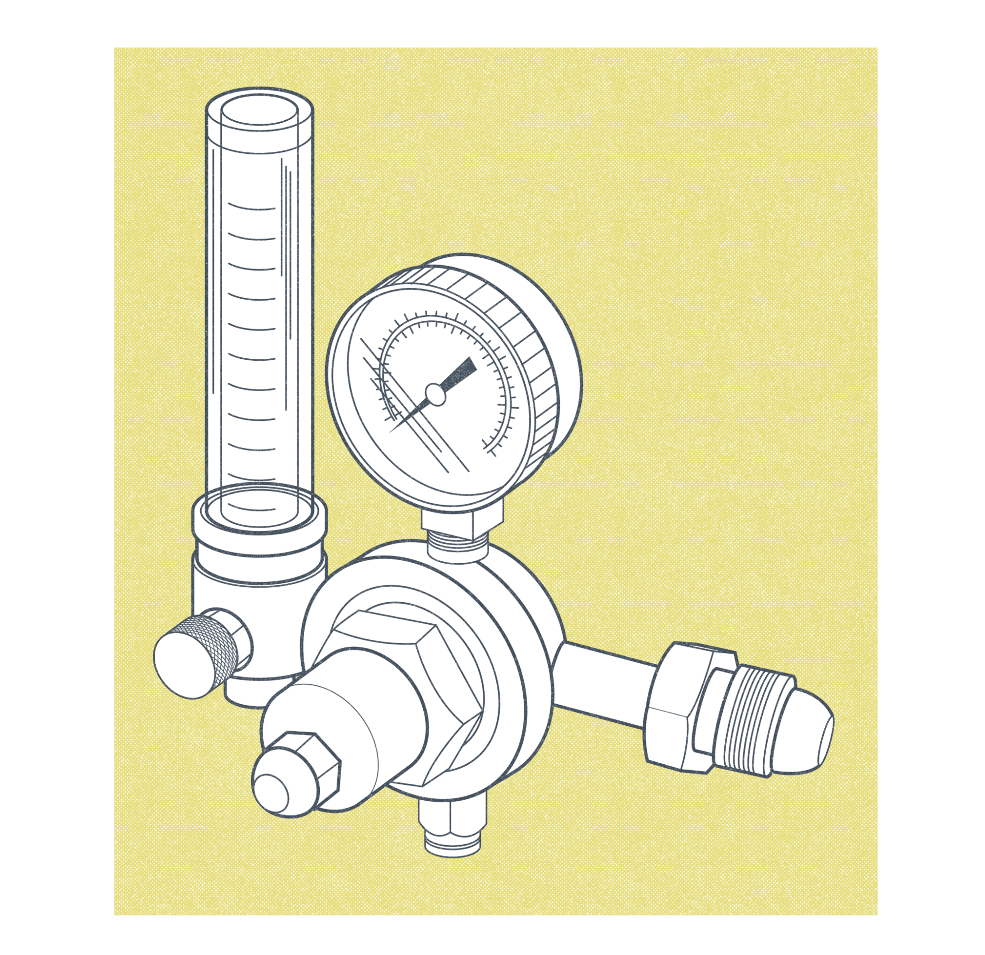
Regulator and flow meter combinations will be most commonly used in GTAW. The regulator shows how much pressure is in the high-pressure bottle and has a set pressure on the flow meter for a consistent flow of shielding gas. The flow meter will control the amount of gas flowing in cubic feet per hour (CFH).
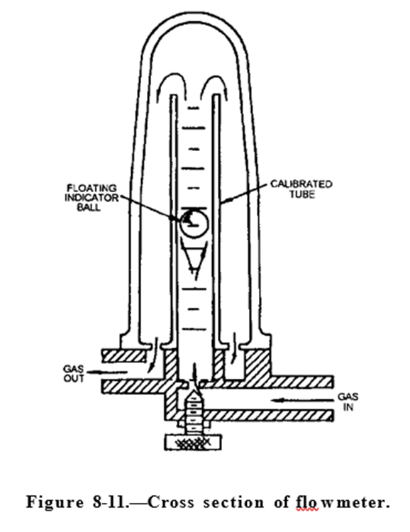
As Figure 11.10 depicts, the gasses flow in and float a ball in a plastic or glass tube and then filter out of the welding machine or directly to the torch, depending on the set up you are running. You take the reading on how gas is flowing from the top of the ball. This can be adjusted depending on the requirements of what you are welding. It’s very important to ensure the flow meter is positioned at 90 degrees to ensure an accurate reading.
Shielding Gasses
It is very important to understand the dynamics of the shielding gasses used in GTAW. Two inert (non-reactive) gasses—argon and helium, or a mixture of the two—are used to protect the molten weld pool and tungsten during welding.
Argon is by far the most commonly used gas in GTAW for its cost and availability. The weight of argon is 39.948 atomic mass units (amu) per mole, making it heavier than air. This means it helps create a blanket over a flat weld to protect it from contamination. Argon also helps produce a very smooth arc.
Helium was the first inert gas used for GTAW but is now less commonly used because of its cost. The need for a higher flow rate when using helium also increases the cost. The atomic weight of helium is 4.0026 amu, making it much lighter than air so it will not pool in a valley when welding in the flat position. The advantages of welding with helium are a hotter arc creating deeper penetration and faster welding speeds. Using a shielding gas that is lighter than air also makes it good for overhead welding.
Regardless of the gas used, your flow rate should be set to protect your molten puddle. You do not want to turn your flow rate up too high, as this can cause turbulence and lead to contamination. A good range to stay in is 11–25 cubic feet per minute. The smaller your nozzle, the less gas you will need.
Setting Up the Welding System
First and foremost, always read the owner’s manual for your welding system. It will have detailed instructions that are specific to your machine.
The first thing you ought to check is the power to the machine. Is it three-phase or single-phase, 110V, 220V, or 480V? Most of the time this information will be labeled directly on the machine.
The next step is to connect your grounding conductor. Depending on your machine, this will either go in the positive terminal or the terminal labeled ground. Then connect your whip to the negative terminal and attach your torch.
Next you connect the shielding gas to the back of your machine if it has a solenoid. If not, there are options to connect the gas directly to your torch, which will need an off valve. Don’t forget to turn the gasses off after every weld.
Specific Safety Considerations for GTAW
When setting up the GTAW welding system, there are some important safety considerations to be mindful of.
- Electric shock: Always insulate yourself from electric shock. Make sure your gloves and clothing are dry. Electricity will follow the easiest path—make sure you are not part of that path.
- High frequency: This has been known to ruin electronics, especially cell phones and pacemakers, in the weld booth. Be very mindful of electronics in the vicinity and do your research.
- Radioactive dust from thoriated tungsten: When sharpened by grinding, thoriated tungsten will produce radioactive dust. Follow the precautions on the Safety Data Sheet for the project, which will likely include but are not limited to avoiding ingesting the dust, washing hands after handling, and wearing a mask that covers the nose and mouth.
- Hexavalent chromium: This is a cancer-causing fume that is produced during the hot work of welding chromium-containing alloys (mostly stainless steel). Welding with GTAW is going to result in lower exposure than other processes, but a respirator with properly rated filters is highly recommended.
- Burns: With GTAW, you are elevating the metal to extreme temperatures. This makes burns the most common injury in welding. Always wear your PPE and be aware of your surroundings. And if it hurts while welding, that’s a sign you must stop.
- Ultraviolet and infrared rays: These rays can cause burns and irritation to the skin and eyes. Cover all skin and never expose your eyes to the arc. At minimum use a shade 9 on your helmet when welding, and if you are having trouble seeing, go darker before you go lighter.
- Argon: Argon may pose a health risk. Exposure to high levels of the gas can cause nausea, vomiting, unconsciousness, coma, and death. No occupational exposure limits have been established for argon. Always follow safe work practices when working with this shielding gas (New Jersey Department of Health, 2016).
Attributions
- Figure 11.4: AC Sine Wave by Nicholas Malara, for WA Open ProfTech, © SBCTC, CC BY 4.0
- Figure 11.5: AC Square Wave by Nicholas Malara, for WA Open ProfTech, © SBCTC, CC BY 4.0
- Figure 11.6: AC Soft Square Wave by Nicholas Malara, for WA Open ProfTech, © SBCTC, CC BY 4.0
- Figure 11.7: Triangle Wave by Nicholas Malara, for WA Open ProfTech, © SBCTC, CC BY 4.0
- Figure 11.8: GTAW Torch Exploded View by Nicholas Malara, for WA Open ProfTech, © SBCTC, CC BY 4.0
- Figure 11.9: Combination regulator and flowmeter by Nicholas Malara, for WA Open ProfTech, © SBCTC, CC BY 4.0
- Figure 11.10: Cross section of flowmeter by Naval Education and Training Professional Development and Technology Center in the Public Domain; United States government work
Deformed from heat
Smooth flow without turbulence.
