11.4 GTAW Operation and Welding Techniques
Karl Fulton
Cleaning Tools
Cleaning is important for all welding, but it is accentuated with GTAW. Here are the tools recommended for cleaning.
- Sanding disk or belt sander: This is a great tool for removing mill scale from mild steel. It is not recommended for use with aluminum or stainless steel.
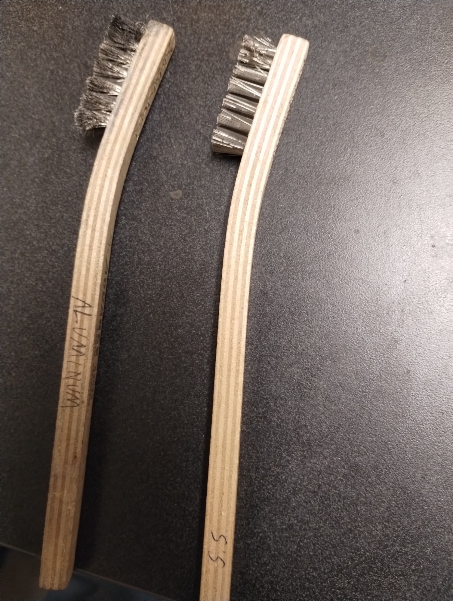
- Stainless steel wire brush: You will want to have one of these for each type of metal you weld. Label them with the material you have designated them for and only use them on that material to prevent cross-contamination. When wire brushing your material, only brush in one direction—and all the way across the surface of the material, if possible. When brushing aluminum, you will want to break through the oxide layer, and you’ll know you have done this when it starts to feel gummy as you brush the material.
- Acetone: Wipe down parts to be welded with acetone and a lint-free rag to remove any oil or other unknown contaminates from the surface of the metal. You may also want to wipe down your filler rod—it can be surprising how dirty filler rods can be.
Fit Up
As with all welding processes, the fit up (contact between parts) is critical. Most of the time, you will want the joints to be as tight as possible. An exception to this rule would be for an open root butt weld where 100% penetration is required. You will want to refer to the Welding Procedure Specifications for restrictions, but for practice and your own knowledge you can make adjustments in a few ways. You can bevel your parts to a knife edge that is where the bevel continues all the way to the edge. When using this technique, you will want the joints to be very close. You can also put a landing on the end of your bevel. This end of the bevel has a small flat spot to create a little thicker material for you to weld with a gap. The land and the gap between your parts should be about the same size as your filler rod.
Make sure your parts are tacked up in multiple spots before welding to reduce the possibility of the joint separating as you introduce heat and tension from the weld. This is very important, no matter the weld joint you are working on. The tension will increase in the direction you are welding.
For a fun experiment, weld a butt joint from one side to the other without tacking the side you are welding to. You will probably see the two parts pull themselves together or even overlap.
Feeding the Filler Rod
There are three options for feeding the filler rod. Try to find a technique that works best for you. The idea is to keep your hand the same distance from the molten puddle the entire time you weld as you feed the filler rod through your hand.
The first technique is to simply push with your thumb. This is good for slower-paced welding. Set your hand with your palm facing up. Put the filler rod in the crux between your palm and thumb and between your ring and middle finger. Then use your thumb to push the rod forward. See Video 11.2 for a demonstration.
A second method is to pull the filler rod forward with your fingers. This gives you a longer stroke for faster welding. Position your palm up with the rod between your thumb and palm, and also through your ring and middle fingers. Squeeze the rod with your thumb to hold it in place. Then collapse your fingers to make a fist and pull the rod forward with your ring and middle fingers as you release with your thumb. Check out Video 11.3 for this technique in action.
A third and final rod-feeding technique is called bunny ears, and it’s great for performing vertical welding. For this method, hold the filler in your palm with your pinky and ring fingers and thumb. Then push the filler down with your middle and index fingers. Video 11.4 shows this technique in action.
GTAW Welding Fundamentals for Ferrous Metals
Mild Steel
Using sharp tungsten, set the power source to DCEN (straight polarity). The current should be set high enough to establish a puddle within two to three seconds of striking your arc. Dip the tip of the filler rod into the puddle and move the arc forward. It is very important to remember to use the molten puddle to melt the filler rod and not the arc. The puddle is what melts your filler.
When you need to terminate your weld, ease off the pedal slowly and fill your crater. Once the arc is extinguished, hold the torch where it is for the duration of your post-flow process. Do not move or even lift up your welding hood. This will disrupt your post-flow as the weld is cooling. The end result should be a uniform weld with slightly convex reinforcement. You do not want a concave weld.
Stainless Steel
| Metal Gauge | Joint Type | Tungsten Size | Filler Rod Size | Cup Size | Shield Gas Flow: Type, CFH,
(L/MN), psi |
Welding Amperes | Travel Speed |
|---|---|---|---|---|---|---|---|
| 1/16”
(1.6mm) |
Butt | 1/16”
(1.6mm) |
1/16”
(1.6mm) |
4, 5, 6 | Argon, 11 (5.5), 20 | 80-100 | 12”
(307.2mm) |
| 1/16”
(1.6mm) |
Fillet | 1/16”
(1.6mm) |
1/16”
(1.6mm) |
4, 5, 6 | Argon, 11 (5.5), 20 | 90-100 | 12”
(307.2mm) |
| 1/8”
(3.2mm) |
Butt | 1/16”
(1.6mm) |
3/32”
(2.4mm) |
4, 5, 6 | Argon, 11 (5.5), 20 | 120-140 | 12”
(307.2mm) |
| 1/8”
(3.2mm) |
Fillet | 1/16”
(1.6mm) |
3/32”
(2.4mm) |
4, 5, 6 | Argon, 11 (5.5), 20 | 130-150 | 10”
(256mm) |
| 3/16”
(4.8mm) |
Butt | 3/32”
(2.4mm) |
1/8” (3.2mm) | 5, 6, 7 | Argon, 13(6), 20 | 200-250 | 12”
(307.2mm) |
| 3/16”
(4.8mm) |
Fillet | 3/32”
(2.4mm) 1/8” (3.2mm) |
1/8” (3.2mm) | 5, 6, 7 | Argon, 13(6), 20 | 225-275 | 10”
(256mm) |
| 1/4”
(6.4mm) |
Butt | 1/8” (3.2mm) | 3/16”
(4.8mm) |
8, 10 | Argon, 13(6), 20 | 275-350 | 10”
(256mm) |
| 1/4”
(6.4mm) |
Fillet | 1/8” (3.2mm) | 3/16”
(4.8mm) |
8, 10 | Argon, 13(6), 20 | 300-375 | 8”
(204.8mm) |
Note: This table is directly excerpted from The Standard in TIG Welding, CK Worldwide (Page 11). The format has been slightly modified to enhance accessibility.
For GTAW welding on stainless steel, begin with sharp tungsten and straight polarity (DCEN). Autogenous welds are commonly used with stainless steel in applications where such a weld is desirable.
There are many different alloys of stainless steel. You will want to be sure you select the correct filler rod for your base materials. Whether you are welding two like materials or two different materials you can normally find a good match on a list like this one at Washington Alloy: STAINLESS Filler Metal Selector Guide.
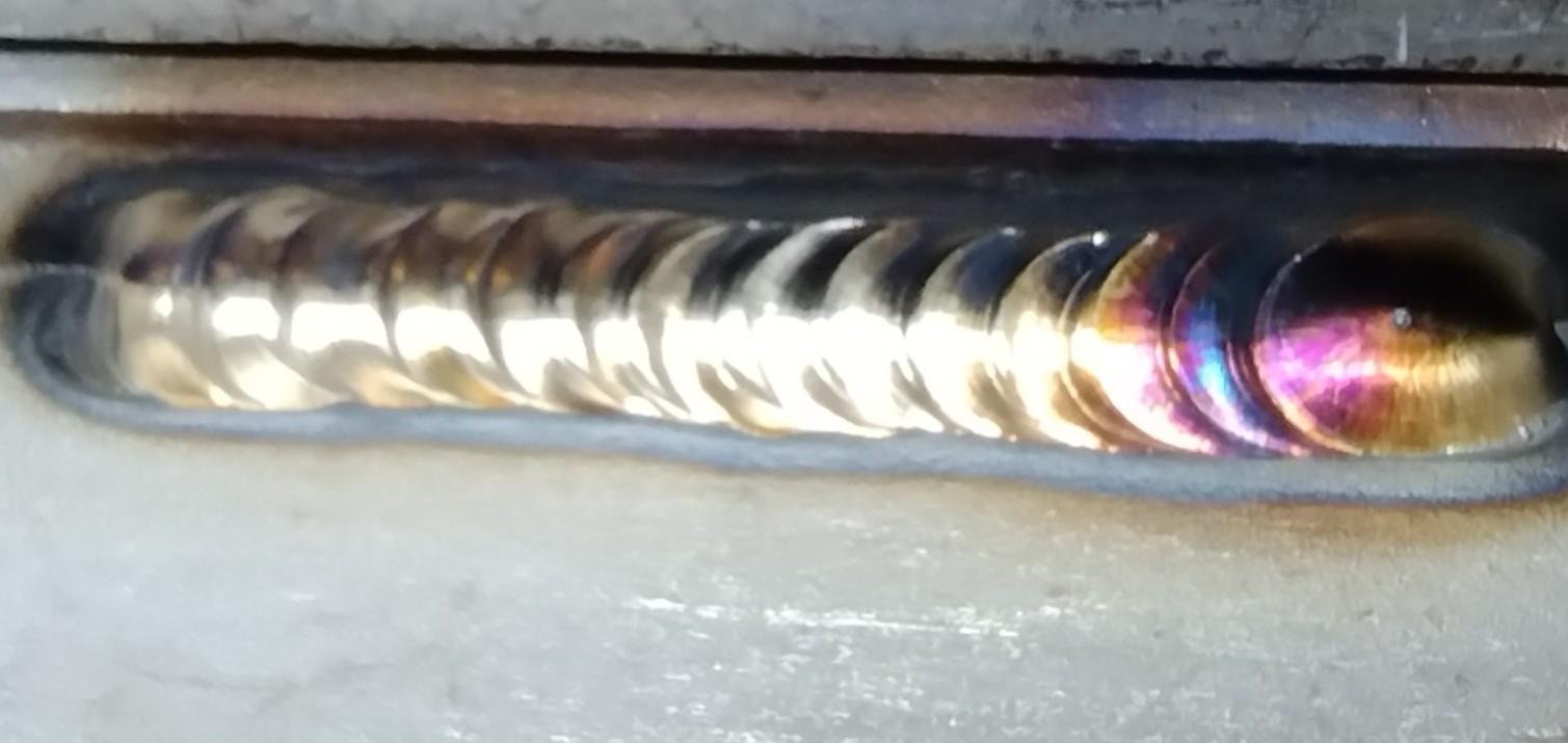
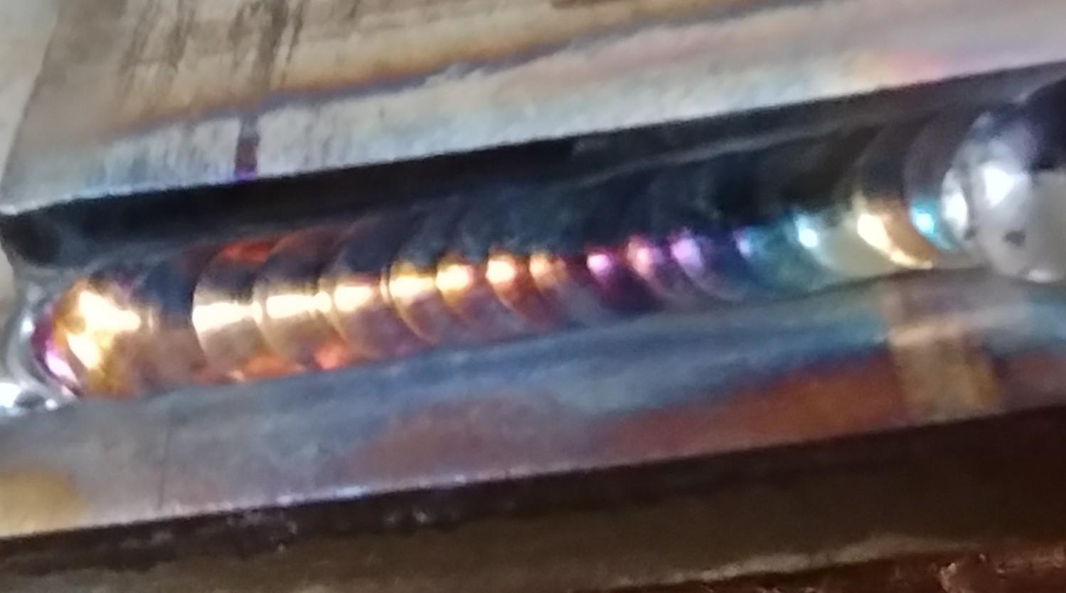
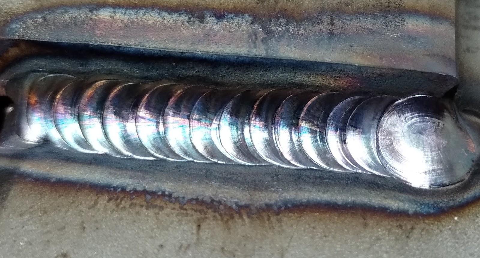
Stainless steel welds similar to mild steel but it is much more sensitive and will give you lots of feedback. It has a high coefficient of thermal expansion and a low coefficient of thermal conductivity. What does that mean for welding? It means the base metal will be more susceptible to distortion. The weld itself has a higher likelihood of overheating as the heat is not being sucked away from the weld by the rest of the base metal. You will want to reduce your heat input as much as possible. The oxidation on the weld will let you know how much heat you have been putting into the weld. Figures 11.15–11.17 show some examples of how the color of the weld can clue you into the quality of your heat input.
Gold or straw colors are what you are looking for, as they indicate proper heat input.
The presence of purple and blue colors indicates that your welding is getting too hot.
If your weld comes out gray it has been overheated, which will reduce its ability to resist corrosion and the weld will be more susceptible to entitlements. To counteract the heat, tighten your arc and increase your travel speed.
GTAW Welding Fundamentals for Non-Ferrous Metals
| Metal Gauge | Joint Type | Tungsten Size | Filler Rod Size | Cup Size | Shield Gas Flow: Type, CFH,
(L/MN), psi |
Welding Amperes | Travel Speed |
|---|---|---|---|---|---|---|---|
| 1/16”
(1.6mm) |
Butt | 1/16”
(1.6mm) |
1/16”
(1.6mm) |
4, 5, 6 | Argon, 15 (7), 20 | 60-80 | 12”
(307.2mm) |
| 1/16”
(1.6mm) |
Fillet | 1/16”
(1.6mm) |
1/16”
(1.6mm) |
4, 5, 6 | Argon, 15 (7), 20 | 70-90 | 10”
(256 mm) |
| 1/8”
(3.2mm) |
Butt | 3/32”
(2.4mm) |
3/32”
(2.4mm) 1/8” (3.2mm) |
6,7 | Argon, 17 (8), 20 | 125-145 | 12”
(307.2mm) |
| 1/8”
(3.2mm) |
Fillet | 3/32”
(2.4mm) |
3/32”
(2.4mm) 1/16” (1.6mm) |
6,7 | Argon, 17 (8), 20 | 140-160 | 10”
(256mm) |
| 3/16”
(4.8mm) |
Butt | 1/8” (3.2mm) | 1/8” (3.2mm) | 7,8 | Argon, 21(10), 20 | 195-220 | 11”
(258.6mm) |
| 3/16”
(4.8mm) |
Fillet | 1/8” (3.2mm) | 1/8” (3.2mm) | 7,8 | Argon, 21(10), 20 | 210-241 | 9”
(230.4mm) |
| 1/4”
(6.4mm) |
Butt | 1/8” (3.2mm) | 3/16”
(4.8mm) |
8, 10 | Argon, 25(10), 20 | 260-300 | 10”
(256mm) |
| 1/4”
(6.4mm) |
Fillet | 1/8” (3.2mm) | 3/16”
(4.8mm) |
8, 10 | Argon, 25(12), 20 | 290-320 | 8”
(204.8mm) |
Note: This table is directly excerpted from The Standard in TIG Welding, CK Worldwide (Page 10). The format has been slightly modified to enhance accessibility.
The materials you’ll use for welding non-ferrous metals like aluminum depend on the type of power supply you have. For a transformer power supply, use green tungsten and ball the end. For an inverter power supply you can use more tungsten options, but be sure to sharpen and then blunt the tip before use. Use AC, starting at a 70/30 split and adjusting as needed.
Why use AC? Aluminum is known as a self-healing metal; an oxide layer rapidly forms on the surface of the metal when it is exposed to oxygen, acting as an armored skin for the aluminum. Pure aluminum melts at approximately 1,200 degrees Fahrenheit and aluminum oxide melts at approximately 3,700 degrees Fahrenheit. This poses a problem when welding, as the aluminum will melt long before the oxide layer and be incredibly difficult to penetrate. However, during the reverse polarity cycle of the AC wave, the oxide layer is broken up. This is considered a cleaning action. You can adjust the balance on your machine to have more time spent on the reverse polarity side of the wave, but you will sacrifice penetration and put more strain on your tungsten. Also, do not mistake this cleaning action to be a replacement for proper material preparation.
When welding aluminum, select the appropriate filler rod for the base metals you are joining. Reference a material chart for this, such as the Aluminum selection chart from Washington Alloy.
Aluminum does not change color when heated; instead, the puddle will appear as a tiny mirror.
When selecting the amperage on your welding machine, a good starting point is to use the ratio of one amp for every thousandth of an inch of thickness of your material. For a 0.125-inch material, that’d equal 125 amps. It would be slightly more for a fillet weld. You should be able to establish a puddle in two to three seconds.
If you will be using a foot pedal, set your amps to 120% of what you need, this way you can establish the puddle very quickly and then immediately start to ease off, giving you more control. Start by dipping the filler into the puddle, ensuring that the puddle is what is melting your filler metal. Once you start you should move pretty quickly: dip and move, dip and move. You will also need to feed your filler metal through your hand every time you dip. As you establish your puddle, do not hold your filler too close; the end will ball up and give you issues.
Aluminum undergoes heat shrinkage as you weld it, and at the end there will be a crater if you do not take steps to fill it. If left, this would leave it susceptible to hot shortness and cracks may start in the crater. These cracks may be tiny and seem insignificant, but imagine it like a small chip on your windshield—it will eventually spread if not dealt with. To fill your crater as you come to the end of your weld, stop moving the puddle, dip twice, ease off the peddle, and back the arc to the position where you were two or three dips ago. This technique will take some practice to master, but with time it will become natural.
Attributions
- Figure 11.14: Stainless steel wire brush by Karl Fulton, for WA Open ProfTech, © SBCTC, CC BY 4.0
- Figure 11.15: S.S. Weld with Proper Heat Input by Karl Fulton, for WA Open ProfTech, © SBCTC, CC BY 4.0
- Figure 11.16: S.S. Weld Getting a Little Hot, But Still Okay by Karl Fulton, for WA Open ProfTech, © SBCTC, CC BY 4.0
- Figure 11.17: S.S. Weld Too Hot by Karl Fulton, for WA Open ProfTech, © SBCTC, CC BY 4.0
