13.2 CAC-A Equipment and Setup
Stephanie Oostman
Components
The information included in this section is generalized, and you should check the operating manual and manufacture’s recommendations for the specific setup procedures, limitations, and safety considerations for your equipment.
We already noted the similarities of SMAW and CAC-A equipment. Most welding machines that are capable of SMAW can also be used to perform CAC-A with a few additional pieces of equipment.
To set up a welding machine for manual (versus semiautomatic) CAC-A you will need the following:
- A constant current (CC) welding machine capable of at least 28V output.
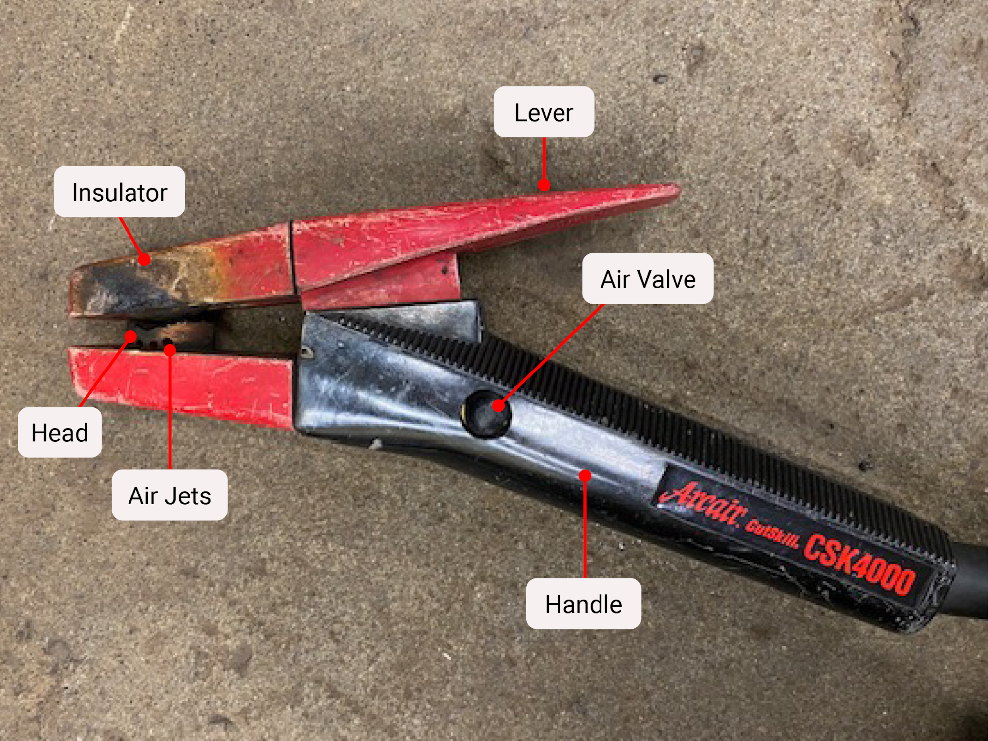
- A CAC-A electrode holder (see Figure 13.1).
- A ground clamp.
- Carbon arc electrodes capable of the polarity you need.
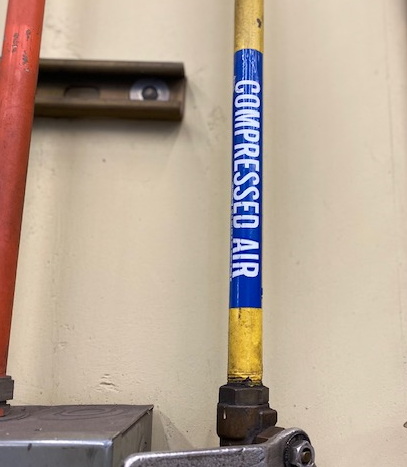
- Compressed air that can be supplied at 80–100 psi.
- An air hose for the compressed air supply.
Power Source
The power source can be either AC or DCEP, however the CAC process requires higher output than some welding machines are capable of producing, making them an ineffective choice for this process. Running a machine at the higher output needed for CAC may cause the machine to overextend its duty cycle. Consult the manufacturer’s recommendations for the machine’s duty cycle. Unless the machine is a heavy industrial type that is capable of 100% duty cycle, avoid overloading your welding machine and take breaks.
The electrode type and its diameter as well as the material to be cut may also impact which polarity to select. Minimum electrode diameters, polarity, amperage, and air pressure settings will all be dictated by what material you are cutting and how thick it is. This is no different than most welding procedures. For example, a one-quarter-inch electrode on DCEP has a range of 200–400 amps and can be used to cut carbon steel, stainless, copper and nickel alloys, aluminum and cast iron.
Compressed Air
Air should be supplied from 80–100 psi. While you can use higher than 100 psi, it does not make the removal of molten metal more effective. The air line needs to have at least an inner diameter of 0.375 inch, and the air compressor must meet the needed capacity to adequately produce a clean, effective cut. For lighter duty work, these recommendations can vary, such as with air pressure as low as 40 psi and an air line with an inner diameter of 0.25 inches. If the air pressure is not sufficient, the operator will not be able to produce a smooth, uniform cut. Inefficient cutting can also happen if the diameter of the air hose is too small, as it will create a constriction of airflow to the electrode holder.
Note: that oxygen should never be used in place of compressed air in the CAC-A process.
Torch
The modern day CAC-A torch is designed to bring together the electrical cutting power of the process and the blasting power of compressed air.
Both the upper and lower jaws of the CAC-A electrode holder are insulated and the lower jaw has a head with holes to allow compressed air through. The head can be rotated to be used in different angles or positions and both jaws only have one groove that can accept a multitude of electrode sizes.
Not all torches are created equal. Just like different electrodes are designed for different amperages, different torches are also rated for different amperages. Using a lower amperage-rated holder may be dangerous or cause damage to the holder and other equipment.
Setting up the System
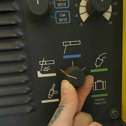
When first setting up your welding machine for CAC-A, take a look and see if it has a setting for CAC-A already available. If it does, you can simply select that program on the machine.
For carbon steel applications, connect the ground clamp to the negative terminal of a CAC-A capable welding machine and connect the end of the CAC-A electrode holder to the positive terminal.
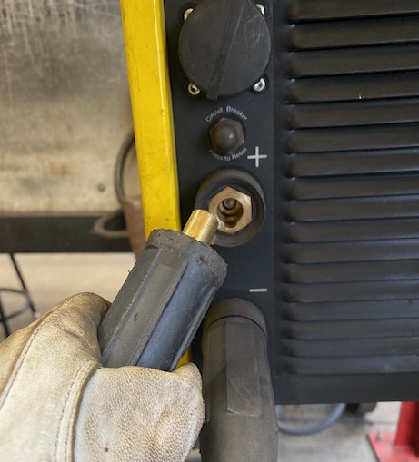
This is now set up for DCEP (reverse polarity). Remember, DCEN should not be used for the CAC process.
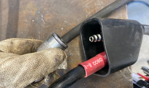
Next, connect compressed air to the CAC-A torch via an air hose with an inside diameter of at least 0.375 inches. The air pressure will need to reach 40–80 psi for general applications but may require upwards of 100 psi for heavier duty needs.
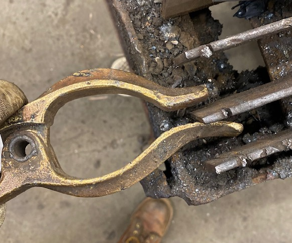
Don’t forget to connect your ground clamp to your cutting table to complete the electrical circuit.
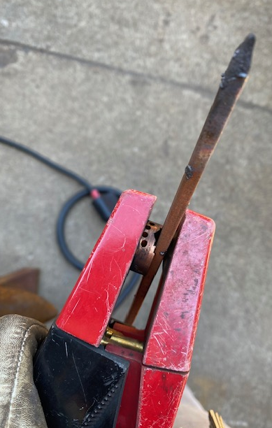
Then select a carbon arc rod. When placing the electrode in the holder, the end should be within 6 inches of the air holes, but not closer than 2 inches to prevent damage to the equipment.
When working, position the electrode holder so that the air holes are on the bottom—this allows for the air to effectively blow the molten dross away.
Next, set the voltage output on your welding machine.
CAC Electrodes
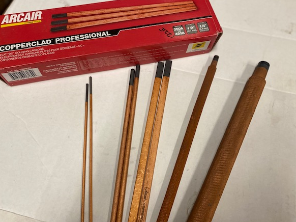
Electrodes used for CAC-A may be copper coated or plain graphite. The copper coating on the electrodes keeps them from overheating; the copper also increases their conductivity and arc stability when used at higher amperages and can improve their durability. Both types of carbon arc rods are fragile, and they and should not be left in the rain or in moisture.
If you are using alternating current (AC) when cutting, then a special electrode type must be chosen. These AC electrodes contain other elemental additives which aid in their stability.
Carbon electrodes come in a multitude of sizes, each rated to withstand more or less amperage, and they come in round, rectangular, or diamond shapes.
Some electrodes can be joined together to reduce waste, and also to increase productivity in robotic and semiautomatic operations.
Attributions
- Figure 13.1: CAC-A Electrode Holder by Stephanie Oostman, for WA Open ProfTech, © SBCTC, CC BY 4.0
- Figure 13.2: Compressed Air Line by Stephanie Oostman, for WA Open ProfTech, © SBCTC, CC BY 4.0
- Figure 13.3: A carbon arc electrode in the electrode holder by Stephanie Oostman, for WA Open ProfTech, © SBCTC, CC BY 4.0
- Figure 13.4: CAC-A setting selection by Stephanie Oostman, for WA Open ProfTech, © SBCTC, CC BY 4.0
- Figure 13.5: The electrode holder is connected to the positive by Stephanie Oostman, for WA Open ProfTech, © SBCTC, CC BY 4.0
- Figure 13.6: Air hose connection into the CAC-A electrode holder by Stephanie Oostman, for WA Open ProfTech, © SBCTC, CC BY 4.0
- Figure 13.7: Connect the group clamp by Stephanie Oostman, for WA Open ProfTech, © SBCTC, CC BY 4.0
- Figure 13.8: Carbon arc electrodes by Stephanie Oostman, for WA Open ProfTech, © SBCTC, CC BY 4.0
