15.2 Groove Welds
Cameron Kjeldgaard
Groove Joints and Terminology
Whether performed with manual or semi-automatic arc welding processes, groove welds are probably the most widely produced welds. Groove welds apply to all five of the basic weld joints previously discussed.
A groove weld is a preparation or opening between two workpieces that provides space for weld metal to be deposited. The AWS defines groove weld as such: “A weld in a weld groove on a workpiece surface, between workpiece edges, between workpiece surfaces, or between workpiece edges and surfaces” (American Welding Society, 2010, p. 21).
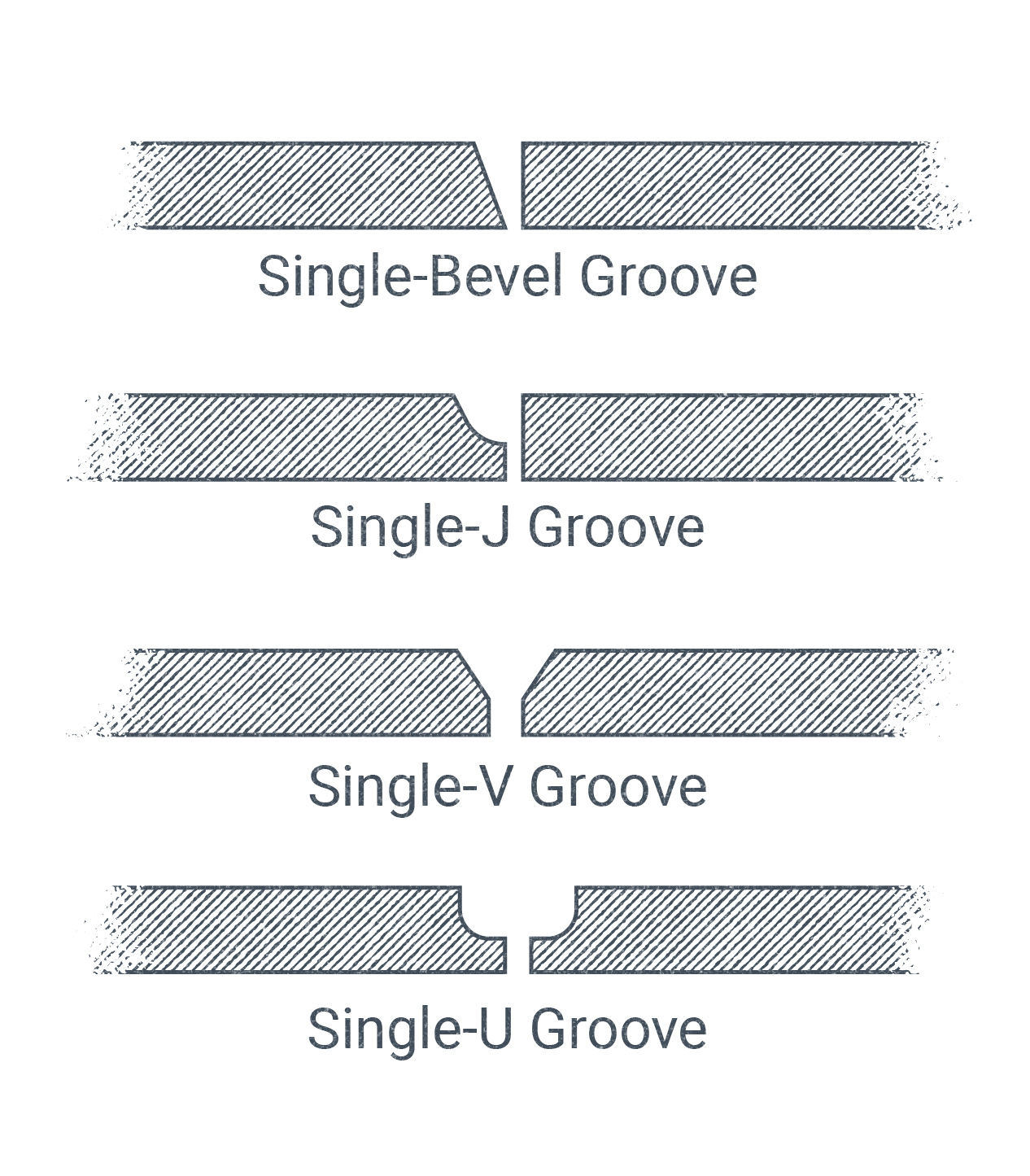
Most groove welds require some sort of special cut through the thickness of the workpiece to increase the penetration of the weld into the material and increase weld strength (an exception is a square groove weld, which doesn’t require special cuts to prepare the groove; however, it is typically only applied to thinner materials or joints that don’t require a high level of strength). In industry, these cuts are colloquially referred to as an edge preparation. Figure 15.5 illustrates the geometry of the different types of groove weld joints. There are many groove preparations that may be cut into the edges of workpieces, each with their own advantages, disadvantages, and applications. These different joint preparations also have a variety of terms to describe them and dimensions to measure them. We’ll cover that material ahead.
Bevels
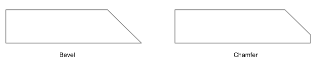
The groove weld is most commonly prepared with a bevel or chamfer. (Note: Although there is a distinction between a bevel and chamfer when these cuts are made for the purpose of welding, it is common in industry to refer to both as a bevel without drawing a distinction; moving forward, we will do the same in the text.) Bevels are one of the most commonly used edge preparations in groove welds because they are fast and simple to make while also greatly increasing weld strength.
Bevels have several associated terms and dimensions to know about:
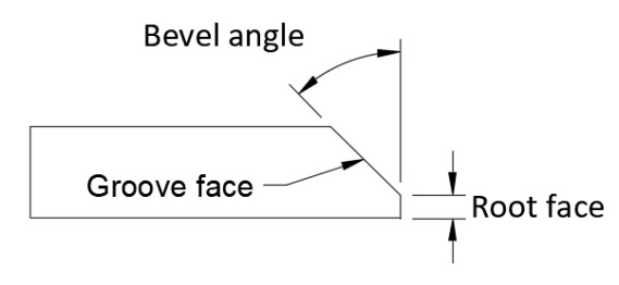
- The angled surface made by the bevel cut is referred to as the groove face. Other types of grooves may have a more complex surface than a simple bevel, but the groove face may be considered the entire surface exposed by the preparative cut.
- The bevel angle is the angular dimension of the bevel cut.
- When the workpiece is not beveled to a point, a root face is present and is expressed as a linear dimension. The root face is also referred to as a landing.
- The bevel depth is a linear measurement of how far below the material’s surface the bevel cut extends. Bevel depth and the resulting groove depth, once assembled with another joint member, have the strongest influence on the finished weld size and strength..
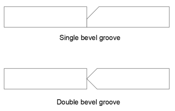
These edge preparations have one more complicating factor, and that is whether one or both sides of the same joint member are beveled. For instance, if only one side is prepared in a bevel groove, it would be called a single bevel groove. And so it goes that if both sides are prepared in a bevel groove, we would refer to it as a double bevel groove. This same naming convention of single and double applies for all the groove types and fillet welds we will discuss going forward.
Bevel Grooves and V Grooves
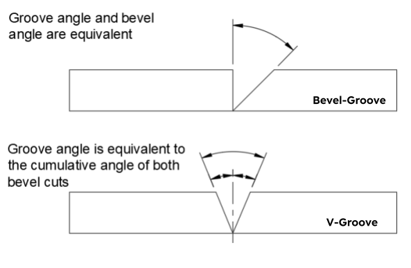
Bevels are used in both bevel groove and V groove weld joints. In a bevel groove weld only one of the joint members is prepared with a bevel. This means the total groove angle is equal to that of the bevel. In a V groove, however, both joint members are prepared with a bevel so the two bevel angles are added together to compute the groove angle.
J Grooves and U Grooves
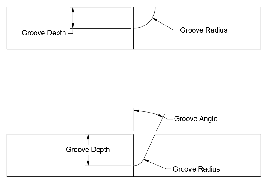
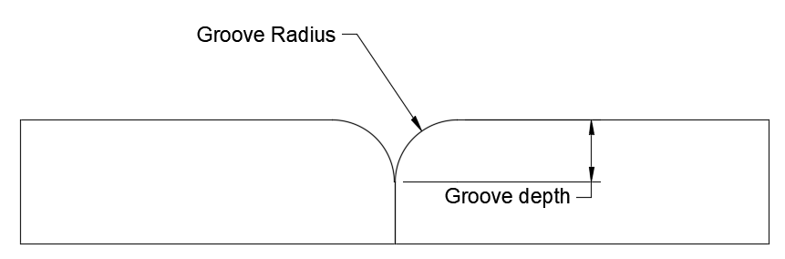
In J grooves and U grooves, the groove face is radiused rather than simply angled. Therefore, these cuts are more difficult to prepare than simple angled bevels and must be prepared by hand, which is time-consuming, or with the use of a machine, which requires specialized tools and equipment. These grooves are commonly used on materials that are sensitive to cracking or distorting during welding, as the curved geometry can more evenly distribute the heat of welding and reduce the stress it puts on the material. This groove geometry is the result of back-gouging operations.
The curved groove is measured by a groove radius; if this radius is equal to the bevel depth, this measurement describes the whole bevel. In a J groove or U groove where the bevel depth is greater than the groove radius, there will typically be a groove angle as well.
From observing Figure 15.5 you may have noticed that the relationship between the J groove and U groove is similar to that of bevel and V grooves in that in the former only one workpiece edge is prepared while in the latter both are prepared.
Flare Bevel and Flare V Grooves
Similar to J grooves and U grooves, flare bevel and flare V grooves also have a radiused groove face—however, it is an outside radius rather than an inside radius (see Figure 15.11). This radius is always equal to the bevel depth. These grooves are not often purposefully cut but are usually a result of the shape of what is being welded together. The shape of these grooves is not ideal, as the groove becomes extremely narrow close to the joint root, which limits weld penetration into the joint root.
Groove Weld Sizing
It is important for welders to know that there are distinct terms for talking about an unwelded joint versus a finished weld. The same goes for measurements related to unfinished or finished welds. The above sections discussed the terms and measurements used to describe the joints prior to welding. In this section we’ll cover special terms to describe the anatomy of finished welds.
Before delving into the specific parts of the finished groove weld, let’s lay out some more generic terms that make up the welder’s everyday vocabulary:
- Base metal refers to the metal that is to be welded together. It does not allude to any specific type of metal; for instance, if I wish to weld two pieces of steel together, or perhaps two pieces of aluminum, I would refer to those pieces as the base metal.
- Filler metal, which typically comes from the welding electrode or a separate welding rod, is the additional metal that has been deposited in the joint of the melted and fused bas metal. Filler metals are used in most welding processes with only a few exceptions.
- Weld metal is used to describe all added filler metal and any of the mixed-in base metal that have been melted, mixed, cooled, and solidified to compose the finished weld.
- Weld bead is the resulting weld metal from a single-pass weld.
- Weld pass refers to a single progression made by the welder along the weld joint. Some weld grooves, if they are small enough or the bead is big enough, may be filled in one pass. Other grooves will require the welder to complete multiple passes along the joint. We call these welds single-pass and multi-pass welds, respectively.
With the above terms in mind, it will be much easier to comprehend Figure 15.12, which examines the different parts of a completed weld.
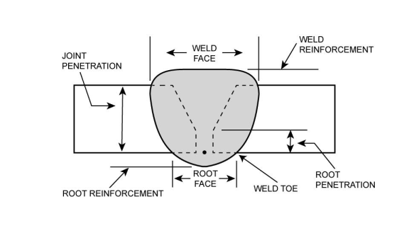
The span of the weld face is given as a linear measurement of the weld width. In the case of the weld shown in Figure 15.12, weld metal has melted all through the joint root, exposing a root face. Where the weld face and root face intersect at the unmelted base metal is referred to as the weld toe.
Where the weld metal extends past the surface of the base metal at the weld face and root face are known as weld reinforcement and root reinforcement, respectively. In industry this reinforcement is sometimes called a weld crown, and may also be referred to as melt-through or burn-through. A linear measurement of these reinforcements are used to define them. If the weld face is above the weld metal surface it is positive. Positive reinforcement is also called convexity, and weld convexity is not considered an effective part of the weld because too much convexity can be detrimental. If there is no reinforcement and the weld face is in line with the base metal surface, the weld would be considered flush. Reinforcement is negative if the weld face is below the base metal surface, also called concave. Typically weld grooves must be at least filled flush, but in some applications concavity may be acceptable or even desirable.
How far the welding heat source melts into the groove is called penetration, and they are expressed as linear measurements. Root penetration is penetration of weld metal into the joint root. Joint penetration is the depth of weld metal penetration past the base metal surface; it is the original groove or bevel depth plus any root penetration. Groove weld size is synonymous with joint penetration, and a one-inch groove weld must have one inch of joint penetration. In Figure 15.12, weld metal has penetrated entirely through the joint thickness. making it a complete joint penetration (CJP) weld. If penetration only extends partially into the joint root, it is called a partial joint penetration (PJP) weld.
The cumulative effect of these factors—joint penetration, weld width, convexity or concavity, etc.—comprise the weld profile, which is the overall shape of the weld when viewed in a cross section. The shape of the weld profile has significant importance when determining the quality and acceptability of the finished welded product.
Attributions
- Figure 15.5: Various Types Of Groove Geometries That May Be Cut Into Material To Prepare It For Welding by Nicholas Malara, for WA Open ProfTech, © SBCTC, CC BY 4.0
- Figure 15.6: Bevel vs. Chamfer by Cameron Kjeldgaard, for WA Open ProfTech, © SBCTC, CC BY 4.0
- Figure 15.7: Parts & Measurements Of A Bevel Cut by Cameron Kjeldgaard, for WA Open ProfTech, © SBCTC, CC BY 4.0
- Figure 15.8: Single Bevel & Double Bevel by Cameron Kjeldgaard, for WA Open ProfTech, © SBCTC, CC BY 4.0
- Figure 15.9: Groove Angle Measurements by Cameron Kjeldgaard, for WA Open ProfTech, © SBCTC, CC BY 4.0
- Figure 15.10: J Groove Dimensions by Cameron Kjeldgaard, for WA Open ProfTech, © SBCTC, CC BY 4.0
- Figure 15.11: Flare V Groove by Cameron Kjeldgaard, for WA Open ProfTech, © SBCTC, CC BY 4.0
- Figure 15.12: Completed Groove Weld by Cameron Kjeldgaard, for WA Open ProfTech, © SBCTC, CC BY 4.0
A manual process is a welding process in which the welder manipulates all aspects of the weld by hand, including arc length, rod or torch angle, weave or oscillation pattern, and travel speed.
A welding process in which the welder manipulates all aspects of the weld by hand, except for the wire-feed speed which is controlled by the feed unit.
A preparation or opening between two workpieces that provides space for weld metal to be deposited.
A preparative cut made on the edge of material to improve weld penetration and size.
A bevel is a preparatory cut made on the edge of a workpiece to increase the size and improve the penetration of a groove weld. Bevels can be cut in various shapes, but they all remove base metal from the weld area, making room for more filler metal to be deposited deeper into the weld joint's thickness
An angular measurement between the faces of two edge preparations.
the process in which the root of a joint is carved away via CAC-A from the backside.
Base metal is the material being assembled to form the weldment, upon which the weld is made. An older term for base metal is parent metal.
Filler metal is the external metal being added to the weld during welding.
Weld metal refers to metal in the finished weld and includes all the filler metal which was deposited and all base metal which was melted during welding.
The weld toe is the intersection of the weld metal and base metal.
When the weld penetrates the base material from one side to the other, in other words the weld bead(s) have been laid down from one side of the base material and built up until they reach the other side of the base material.
Weld profile is the general shape of the weld when viewed in cross section.
