Want to create or adapt books like this? Learn more about how Pressbooks supports open publishing practices.
14.2 PAC Equipment and Setup
Components
The main components of the PAC system are discussed in this section.
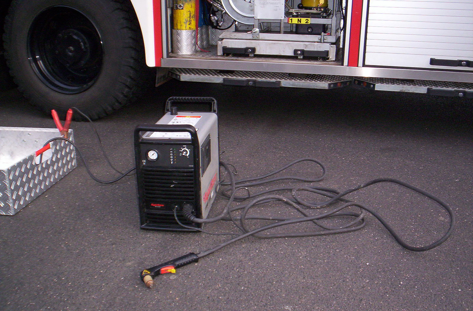
Figure 14.12. Plasma Power Source / Photo Credit: ich selber (Benutzer:Thomas S.), PD
A main component is the power source, which will provide the direct current to produce the arc. The gas or compressed air will also flow through the power source.
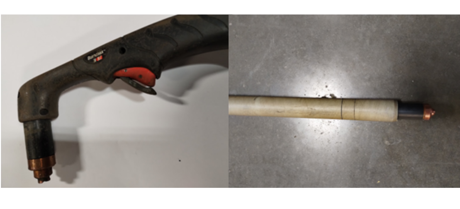
Figure 14.13. Plasma Torch for Handheld vs Mechanized Head / Photo Credit: Karl Fulton, CC BY 4.0
The next main component is the welding torch. A handheld torch is used for the handheld plasma system and a straight torch for mechanized cutting is used for a mechanized plasma system. Handheld plasma torches have a safety over the trigger. However, for the straight torch everything is controlled by the operating table or mechanism.
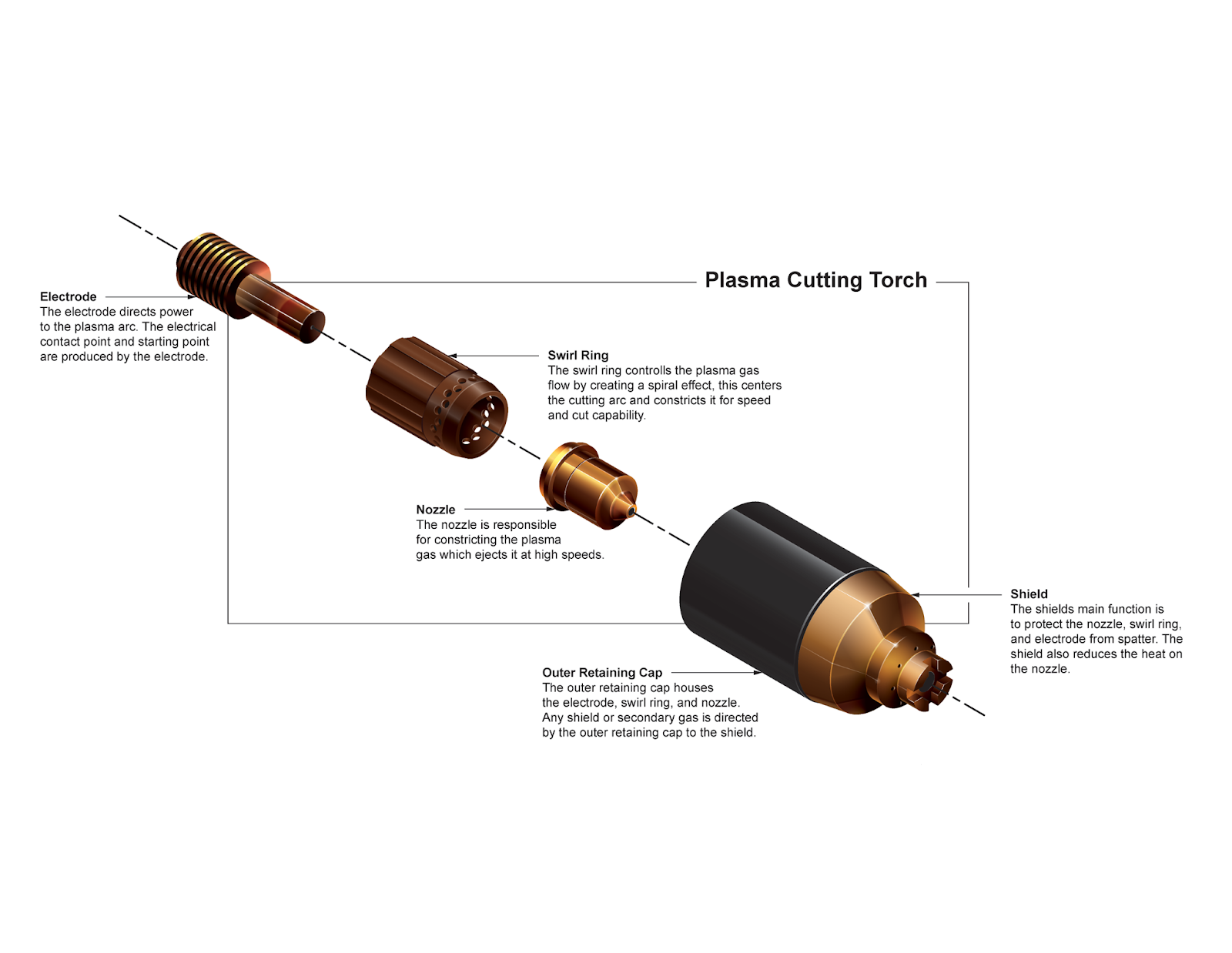
Figure 14.14. From back to front the plasma torch electrode includes an electrode, swirl ring, nozzle, outer retaining cap, and shield. The electrode caption reads, “The electrode directs power to the plasma arc. The electrical contact point and starting point are produced by the electrode.” The swirl ring caption reads, “The swirl ring controls the plasma gas flow by creating a spiral effect, this centers the cutting arc and constricts it for speed and cut capacity.” The nozzle caption reads, “The nozzle is responsible for constricting the plasma gas which ejects it at high speeds.” The outer retaining cap caption reads, “The outer retaining cap houses the electrode, swirl ring, and nozzle. Any shield or secondary gas is directed by the outer retaining cap to the shield. The shield caption reads, “The shield’s main function is to protect the nozzle, swirl ring, and electrode from spatter. The shield also reduces the heat on the nozzle.”/ Photo Credit: Kirk Zimmerman, CC BY-NC-ND 4.0