10.2 GMAW Equipment and Setup
Stephanie Oostman
Components
Before we dive in, it may be helpful to know upfront that GMAW uses almost the exact same equipment as FCAW (covered in Chapter 9): a CV power source, wire feeder, welding gun, and even in some cases the same shielding gas. The construction of the electrode is the biggest difference between the processes, because unlike the tubular, flux-filled electrode used in FCAW, GMAW wire electrodes have a solid construction. As you read on, keep in mind that your recollection for FCAW will serve as a good reference for the equipment, setup, and welding techniques used in GMAW.
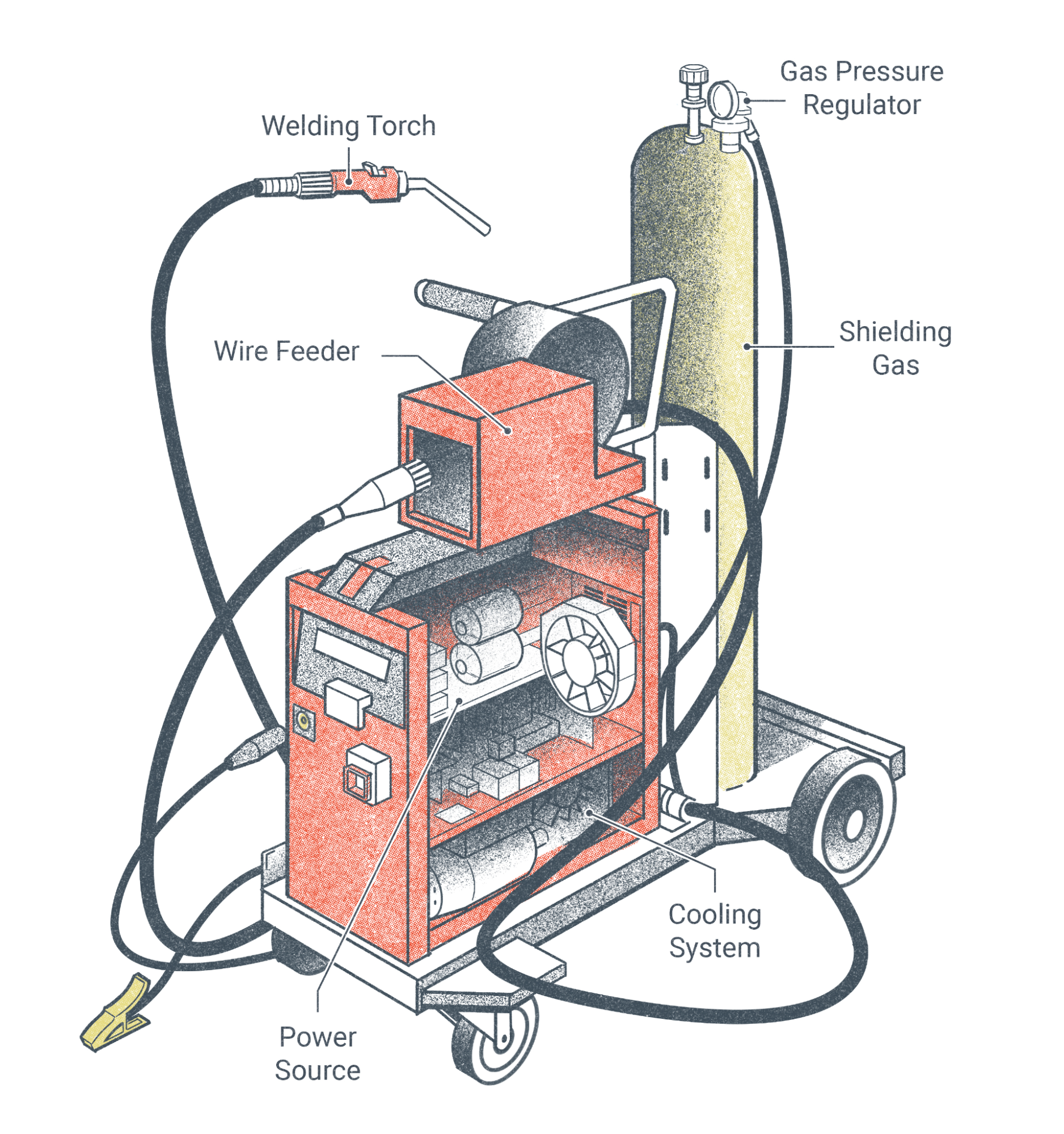
Let’s break down the GMAW setup into its major components:
- Shielding gas
- Power source capable of delivering a direct current (DC) at a constant voltage
- Wire feeder
- Welding gun
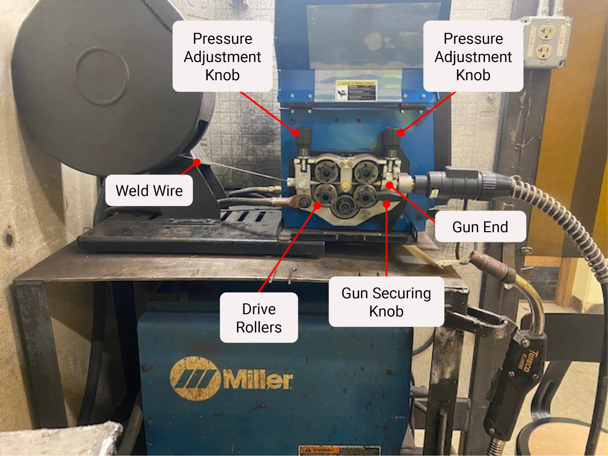
Sometimes the wire feeder components are inside the power source/welder, but other times they are an additional plug-in “remote” that sits on top of or near the welding machine (see Figure 10.5). Regardless of where the wire-feeding portion of the equipment is located, the parts and concept of how they work together are virtually the same.
As stated above, the FCAW-G machine setup is nearly identical to GMAW. In fact, nearly all machines that can be set up for FCAW can also run GMAW with just a few adjustments to components like the drive rollers and tips or nozzles. In the case of welding non-ferrous metals like aluminum, the gun liner would also need to be changed out for a plastic liner (steel coil is used for ferrous materials). Alternatively, a spool or push-pull gun may be used. Spool guns and push-pull guns, which have a different setup than the standard GMAW/FCAW-G machine, were also covered in Chapter 9.
As a review, a spool gun takes the wire reel and puts it at the gun handle near the welder. This is a much smaller wire reel, almost like what you may see on a fishing rod. It is used primarily for GMAW welding of aluminum to reduce jamming caused by the aluminum wire getting caught up inside the liner, which can happen if the welding gun cable is longer than four feet. This can be very problematic for fabrication companies that manufacture a lot of aluminum products, such as fishing boats. in addition, a spool gun gives the welder a longer gun cable and improves portability to do the work since they can move further than four feet from the machine.
Push-pull guns are similar in that they also help cut down on wire jamming and are frequently used with non-ferrous metals, such as aluminum. But unlike spool guns, the wire reel stays inside the machine. Instead there is a second pair of very small drive rollers inside the handle of the gun. This helps pull the wire through the gun cable while the drive rollers in the machine help push the wire through.
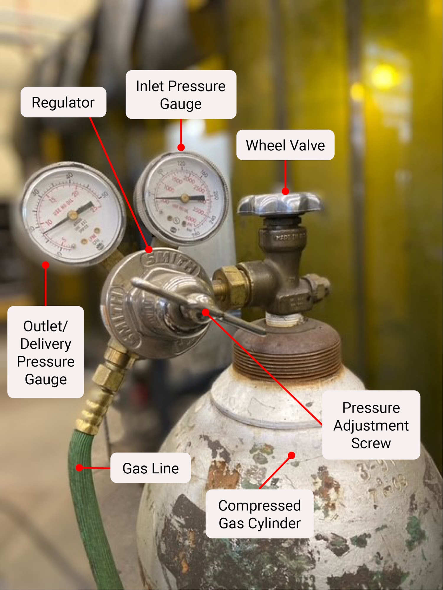
The shielding gas system for GMAW consists mainly of a cylinder of shielding gas, a flow meter to set the amount of gas that is withdrawn from the tank (set in cubic feet per hour, CFH), and a gas line connecting the shielding gas from the flow meter to the welder. Figure 10.6 shows a version of what you may encounter in a welding shop.
It is not uncommon for a welder to have to access the inside of the machine on a regular basis, so it’s recommended that you become familiar with identifying each component and what purpose it serves.
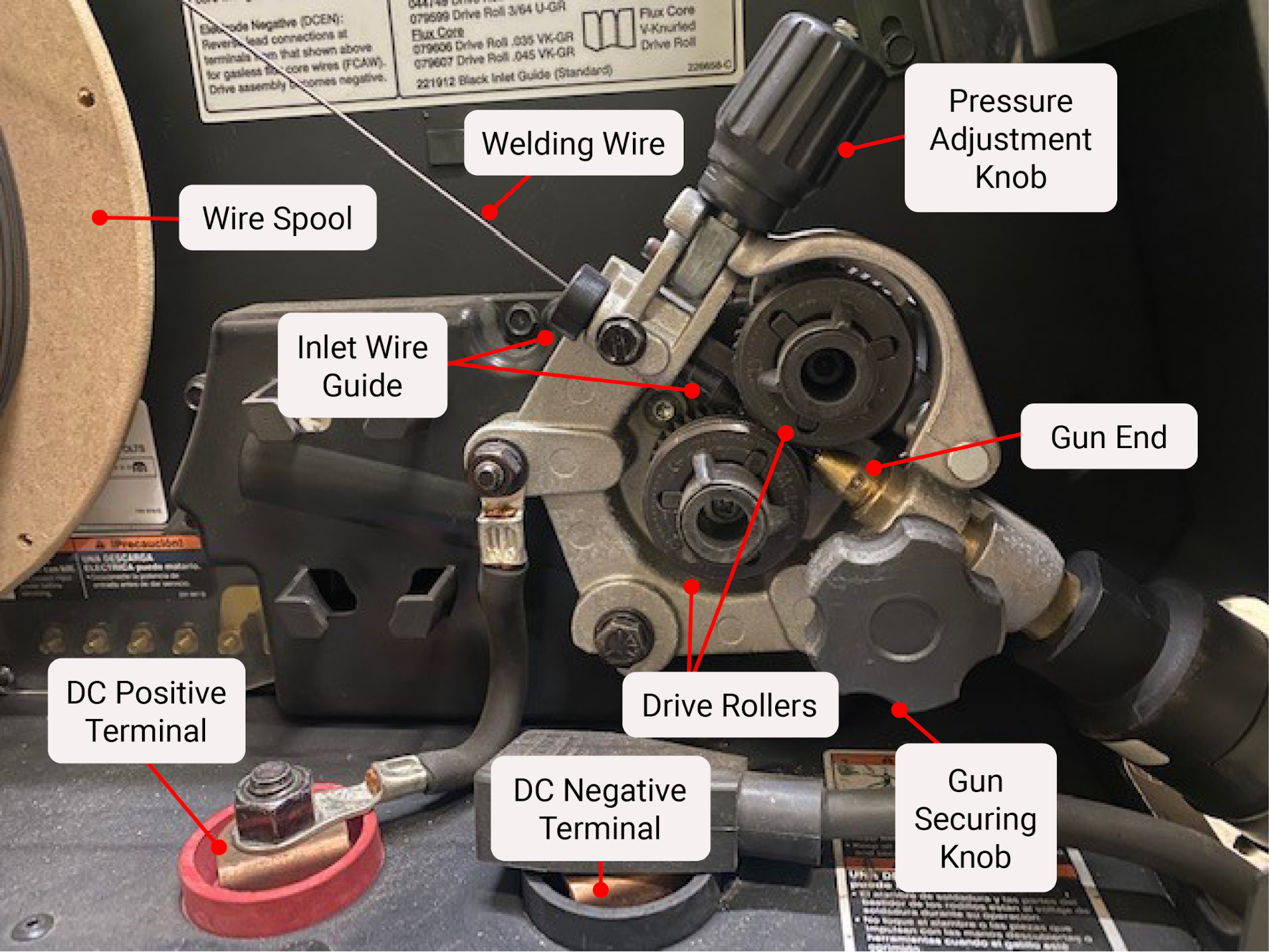
As with any electrical piece of equipment, turn off the machine and, if possible, unplug it before opening the door and making any adjustments. Once opened, you will find something like the image shown in Figure 10.7 inside the welding machine. The following are the CV-capable welding machine components:
- Drive assembly: This is the motor that provides the ability to move the mechanical parts.
- Wire spool: This is the consumable wire electrode wrapped around a spool.
- Inlet wire guide, intermediate wire guide, and outlet wire guide: These are a series of cylindrical cone-like guides for the electrode wire to move through so it stays on course and doesn’t jam. They are typically composed of plastic or brass. All three listed might be present, but some makes and models of machines may only have one or two wire guides.
- Drive rollers: Their function is to move the wire along and help guide the electrode wire through the system. (See Chapter 9; use of drive rollers as they pertain to FCAW is the same for GMAW.) It’s important that the wire diameter and the wire size printed on the side of the drive rollers match. The groove type on the drive rollers matters, as well. For hard wire processes like MIG for steel, a V groove is appropriate, but for softer wire such as aluminum, then a U groove set of drive rollers should be installed.
- Pressure adjustment knob: Increasing the distance (loosening the knob) decreases the pressure applied to the electrode wire from the driver rollers whereas decreasing the distance (tightening the knob) increases the pressure applied to the electrode wire from the drive rollers.
- Gun securing knob
- GMAW gun
- Gun end
- Gun trigger plug
- Gun conduit cable
- Gun liner
- Goose neck
- Washer
- O-ring
- Gas diffuser
- Insulator
- Contact tip
- Nozzle
- Work clamp
Setting Up the Welding System
The process of setting up the machine can be a little confusing the first time you do it. So far, we have already covered the machine’s inner workings and changeable parts. But say you run out of wire, need to change to a different size wire, or are converting over to work on GMAW after using the machine for FCAW. This section covers how to handle those scenarios. However, it does not supersede the manufacturer’s guidelines and recommendations. Instead, it’s always best to follow what the manufacturer recommends for each of their machines, as there will be some subtle differences between products.
If you need to convert from FCAW to GMAW or change to a different wire size and type, start by removing the wire.
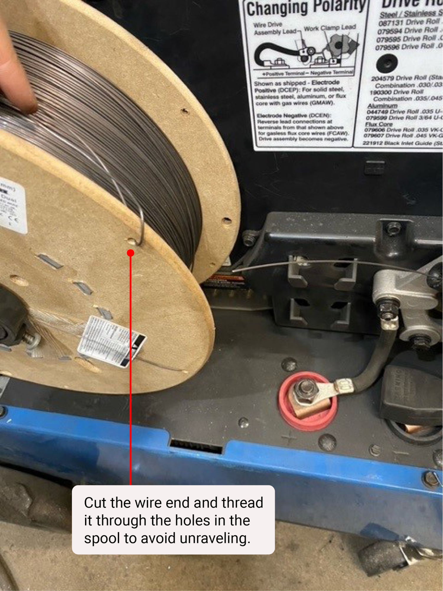
Hold on to the wire as it comes off the spool and clip the wire near the cylindrical guide. Do not let go of the wire connected to the spool—it will unravel the spool and cause a big mess. Instead, wrap the end of the wire to the spool either by weaving it through the spokes of a metal spool or using the holes on a plastic or wooden spool. Make sure it’s secure before you let the end of the wire go. Then remove the whole spool from the machine.
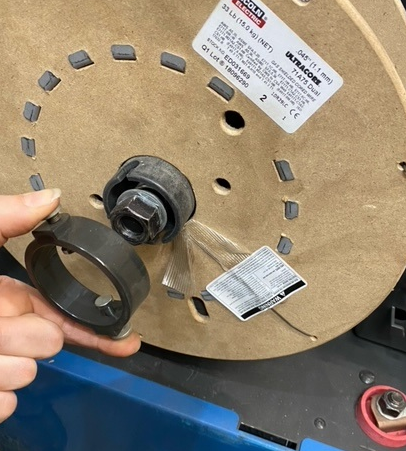
Next, remove the reel from the machine. You may need to release the clip that holds the spool in place.
Next, remove any remaining wire that is left inside the MIG whip.
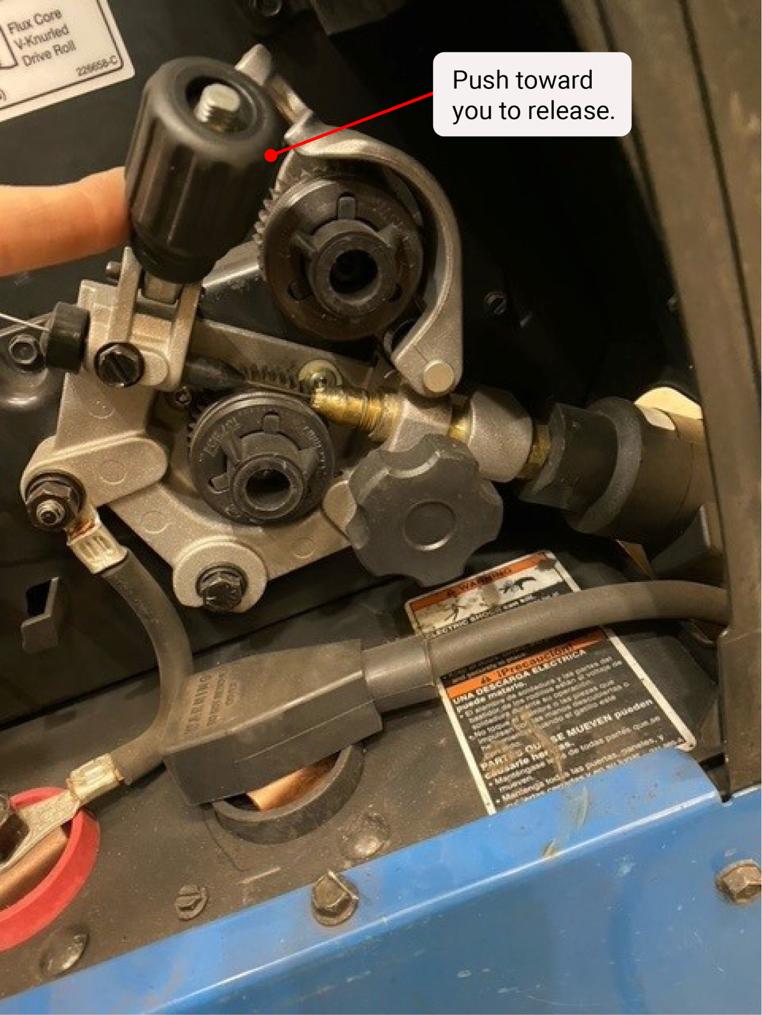
To do so, release the pressure adjustment knob that is holding the drive rollers down, then straighten out the MIG whip—this will make it easier to pull wire through.
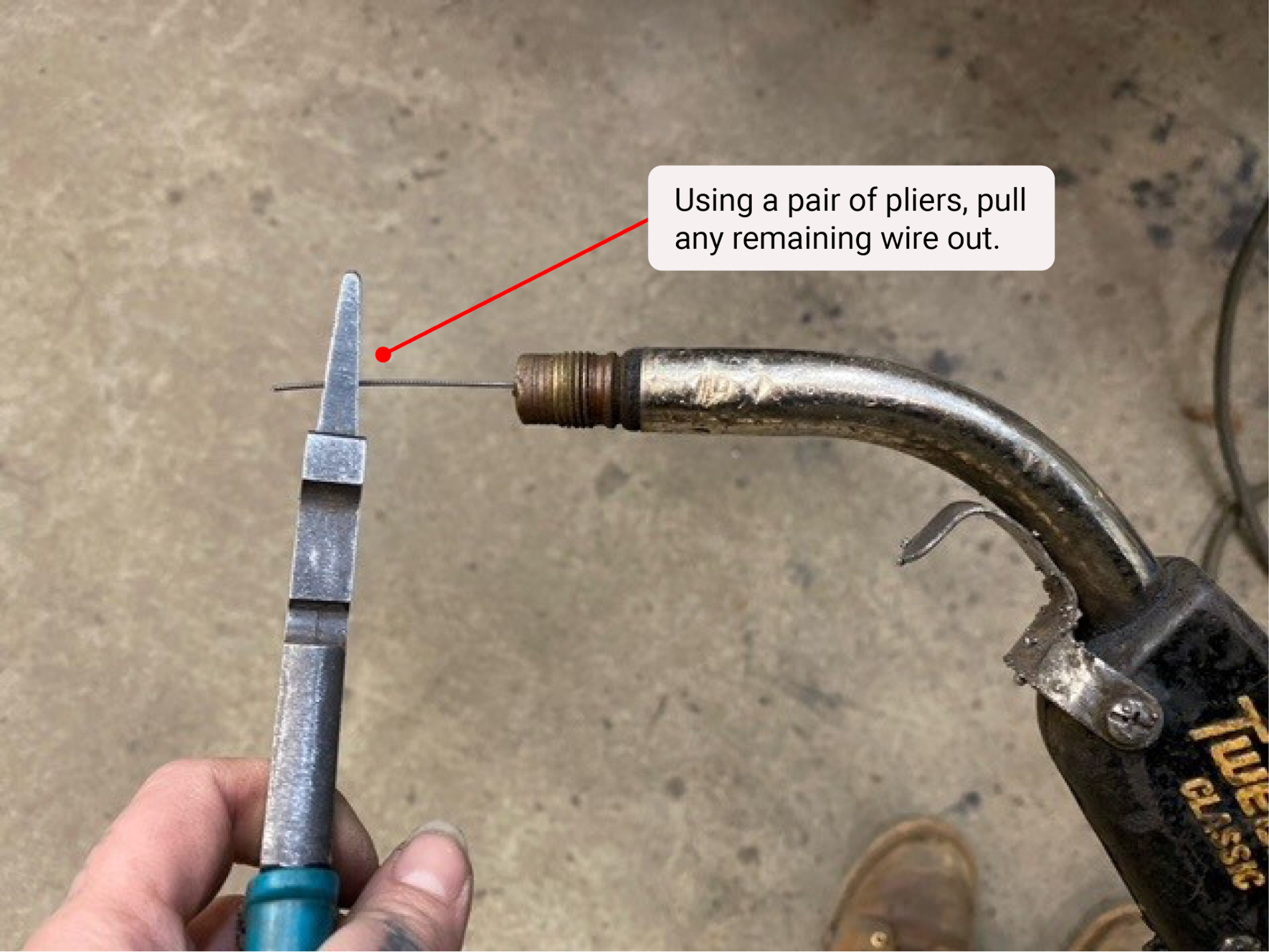
Unscrew the nozzle at the gun’s side and pull off the tip. Using a pair of pliers or MIG welper pliers, grab a hold of the wire electrode sticking out of the MIG gun end and pull it out.
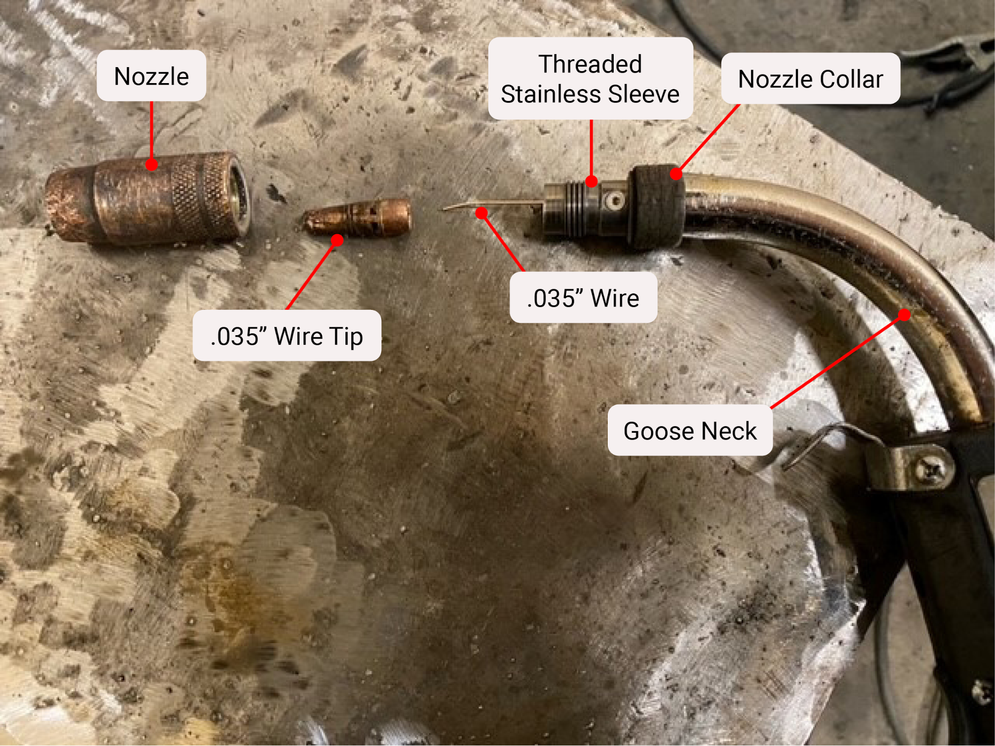
If you are switching wire sizes, you will need another tip for the appropriate size. A different nozzle might also be necessary, but not always.
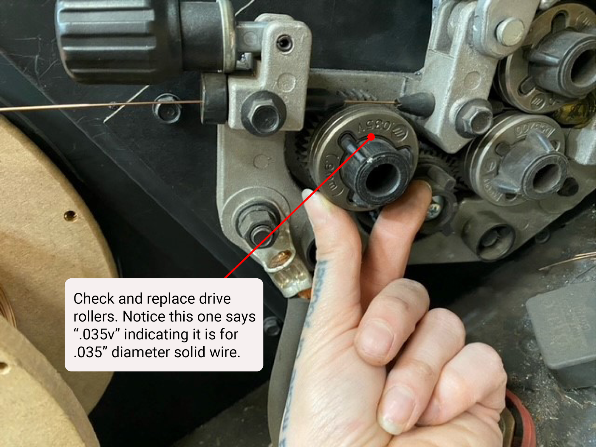
Finally, remove the drive rollers and replace them with the appropriate size in a V groove type.
Now we’ll cover the steps to add wire to the machine.
But first, look at the inlet wire guides shown in Figures 10.10 and 10.13. Notice in Figure 10.10 that the inlet wire guide and drive assembly are angled up, but in Figure 10.13 they are horizontal. This matters when you are adding wire because you don’t want to let the wire bend when you are trying to make it into the inlet guide. Rather, it should flow in the path of least resistance. This means that for the machine shown in Figure 10.10, the wire should be placed so it unspools from the top. For Figure 10.13, the wire should unspool from the bottom. Before you add a new wire into the machine, determine if you’ll need the wire to feed from the bottom or the top and then put the wire on the post that holds the wire in place.
Next, remove the end of the wire from the spool—it’s usually taped or wrapped against the side—and do not let it go. Feed the wire into the inlet guides and into the end of the gun. Gently push the wire into the gun end so it’s secure and you can let the wire go. Then push the pressure adjustment knob back into place, effectively closing the drive rollers together.
Now you can turn the welding machine on. Pull the trigger on the gun handle and watch the wire move through the drive system to ensure there are no snags. Once the wire comes out of the gun tip end, put the new MIG tip and MIG nozzle on. Then the machine should be ready to weld.
Attributions
- Figure 10.4: Gas metal arc welding equipment by Nicholas Malara, for WA Open ProfTech, © SBCTC, CC BY 4.0
- Figure 10.5: Inside a GMAW ‘remote’ by Stephanie Oostman, for WA Open ProfTech, © SBCTC, CC BY 4.0
- Figure 10.6: A gas cylinder and regulator by Stephanie Oostman, for WA Open ProfTech, © SBCTC, CC BY 4.0
- Figure 10.7: Inside close up of a GMAW/FCAW-G wire feeder by Stephanie Oostman, for WA Open ProfTech, © SBCTC, CC BY 4.0
- Figure 10.8: Secure the wire by Stephanie Oostman, for WA Open ProfTech, © SBCTC, CC BY 4.0
- Figure 10.9: Removing the reel by Stephanie Oostman, for WA Open ProfTech, © SBCTC, CC BY 4.0
- Figure 10.10: Pressure adjustment knob by Stephanie Oostman, for WA Open ProfTech, © SBCTC, CC BY 4.0
- Figure 10.11: Clear the gun of wire by Stephanie Oostman, for WA Open ProfTech, © SBCTC, CC BY 4.0
- Figure 10.12: Basic MIG (GMAW) gun components by Stephanie Oostman, for WA Open ProfTech, © SBCTC, CC BY 4.0
- Figure 10.13: Driver rollers by Stephanie Oostman, for WA Open ProfTech, © SBCTC, CC BY 4.0
A knob that increases or decreases the distance between the top and bottom drive rollers, which the wire passes through.
A knob that secures the rear end of the welding "gun" or whip into the machine.
