10.4 GMAW Operation and Welding Techniques
Stephanie Oostman
GMAW Modes of Transfer
At the beginning of this chapter, you read a reference to how there are “modes” in GMAW welding. But what does that mean, and what distinguishes the modes?
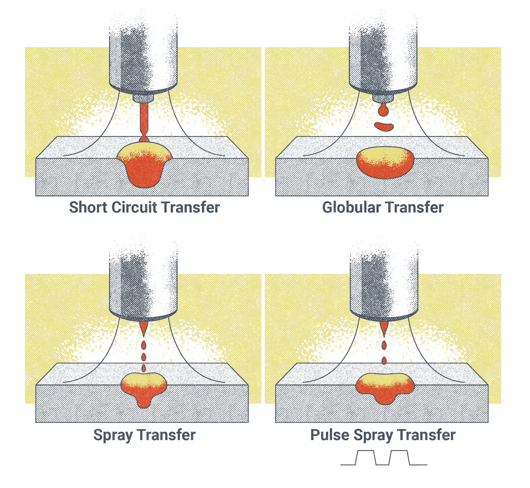
We have already discussed how MIG and MAG welding offer versatility. That is because the operator can easily interchange the relationship between wire and heat. This, along with the ability to change wire types, sizes, and shielding gasses, creates different behavioral changes in how the electrode wire melts and gets transferred to the base metal. These are referred to as transfer modes, and they are the key to the GMAW process’s diversity and utility. In GMAW, there are four transfer modes.
Spray Transfer Mode
Spray transfer refers to the behavior in which the wire from the welding machine melts at the tip and deposits into the joint so as to create fine droplets that are equal to or less than the diameter of the electrode wire being used. For this to occur, the machine must reach the transition current, which is the minimum current setting for the welding machine to transition from globular transfer and into spray transfer. It is important to note that the transition current is not universal but rather dependent on variables such as electrical stickout, electrode type, and electrode wire diameter.
For example, a 0.035-inch diameter wire of the ER-70S-6 classification may reach its transition current into spray transfer when the welder is set to 24V–32V and 350–580 inches per minute (IPM).
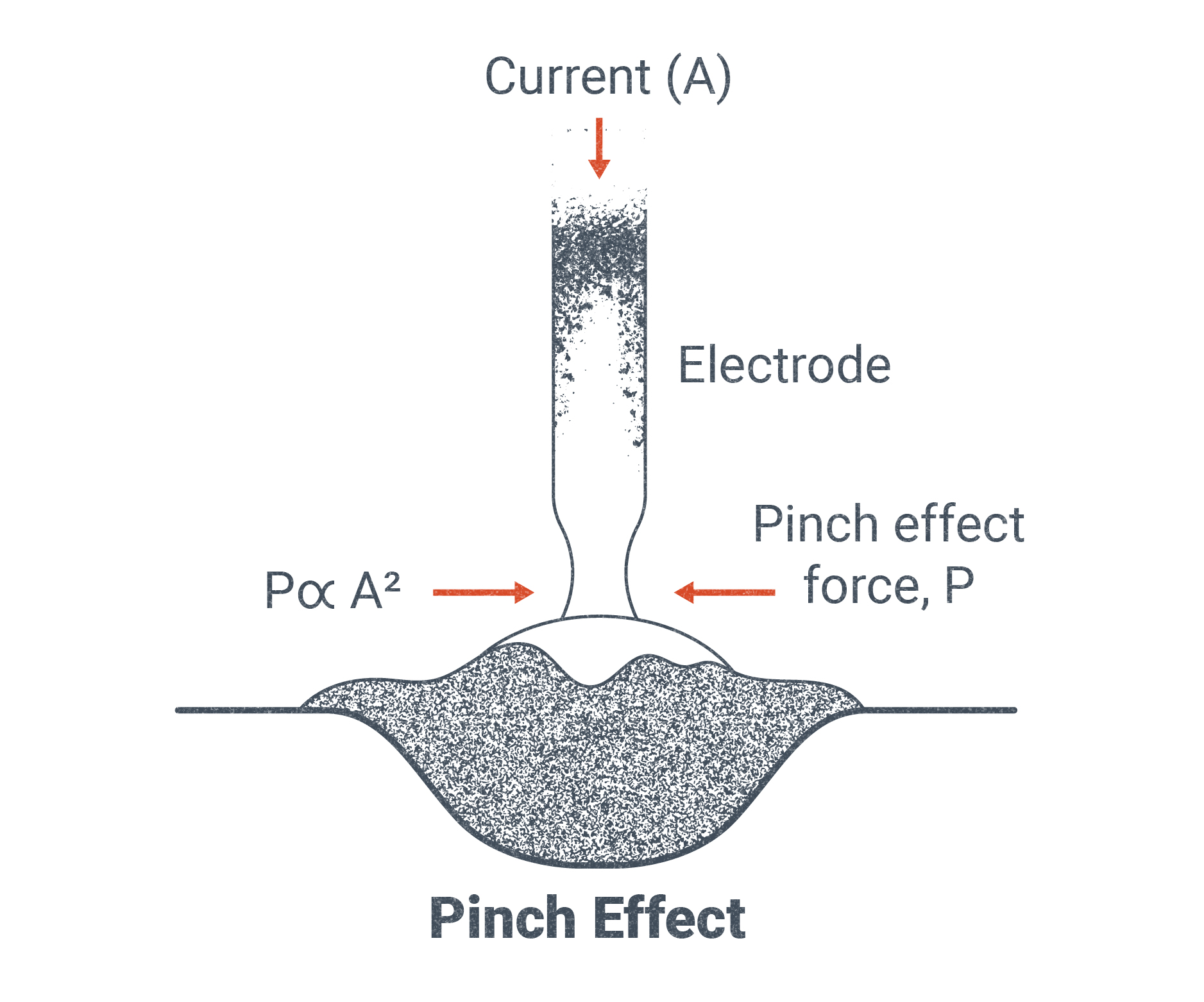
As the consumable wire electrode interacts with the shielding gas and is melted by the electrical arc it results in what’s called pinch force. Pinch force along with surface tension acts as a squeeze or pinch on the end of the consumable wire electrode, allowing a droplet to break free of the tip of the wire and be distributed onto the base metal or joint. For spray transfer, pinch force on the electrode is increased to the point that the molten metal produces a fine conical spray, depositing an even and virtually spatter-free weld with a deeper penetration than the other transfer modes.
For this transfer mode it is important to select the appropriate shielding gas and welder settings in order for a fine cone-like spray to occur. For ferrous applications, a shielding gas of at least 80% argon must be used. For non-ferrous metals such as aluminum alloys a shielding gas of 100% argon is recommended.
Spray transfer is best suited for the flat (1G/1F) and horizontal (2G/2F) welding positions.
Pulsed Spray Transfer Mode
Pulsed spray transfer mode(also called GMAW-P), offers welders the ability to weld spray transfer out of position, such as overhead, and to utilize thicker wire electrodes than traditional spray transfer. It also requires lower heat input, offers 98% electrode efficiency, and can be used to create a consistent root on open joints without the need for a backing bar.
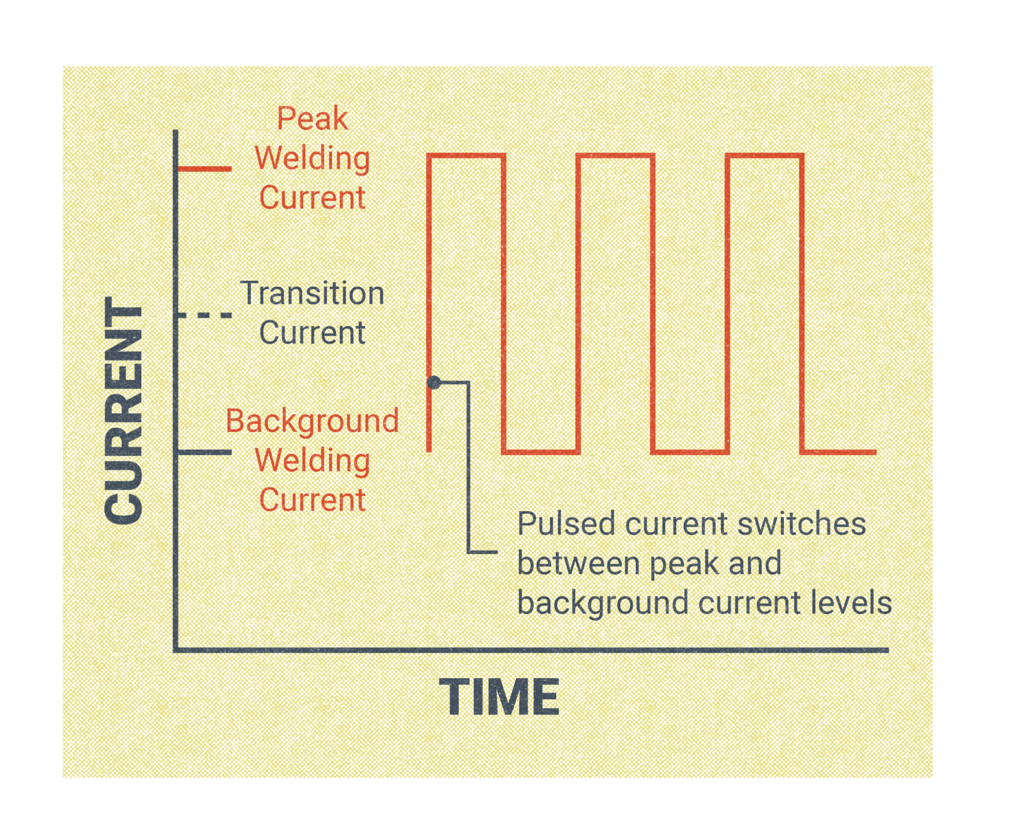
GMAW-P is not available on all MIG/MAG wire feed machines. When it is selected, pulsed spray transfer allows the current to toggle between a preset high current and down to a preset low current. Just like standard spray transfer, when GMAW-P is at the high current, a molten droplet forms at the end of the electrode and is then pinched from the tip and deposited as a fine cone-shaped spray to the joint. But unlike regular spray transfer, the welder will then revert to a low current—during which no metal transfer occurs—before cycling back to the high current. This toggling between the two current settings occurs rapidly and as much as several hundred times a second. The return to a low current drops the overall heat input into the workpiece, allowing spray transfer to be used with thinner base metals and lessening the overall heat distortion. The frequency of this pulsing from high to low increases as the wire feed speed increases.
Short Circuit Transfer
Short circuit transfer mode, or GMAW-S, is one of the most common wire-feeding processes. Like spray transfer, this process uses a solid or hard wire, is impacted by pinch force, and can support a multitude of different wire electrode types and thicknesses. However, there are distinguishing features of the two modes of transfer and reasons for selecting one versus the other.
Short circuit transfer occurs when the welding current is less than 200 amps for a wire diameter of 0.045-inches or less. What is unique to the short circuit transfer mode is that metal is not transferred across the arc—rather, the weld puddle freezes quickly in between these short circuits before the arc is reignited again and the wire electrode makes contact with the puddle once more.This behavior makes short circuit transfer ideal for situations where heat input is a concern and for welding areas with wide gaping or poor fit-up. A welder may also find this welding method more ideal when welding in the 3F/3G and 4F/4G positions due to its rapid freezing ability.
While this transfer mode offers more accessibility and is generally considered easier to learn, it has disadvantages. GMAW-S has a lower electrode efficiency than spray transfer, at about 93%. While short circuit transfer allows for an increase in travel speed, it also increases the potential for spatter and longer post-weld cleanup time. Additionally, welders choosing GMAW-S need to be conscientious of the increased risk of incomplete fusion.
The shielding gas used with short circuit transfer can vary and depends on the overall needs of the weld. Pure (100%) CO2 is used in scenarios where a deeper penetration may be desired, but the operator may sacrifice overall consistency and bead contour. A more common choice is a 75% argon and 25% CO2 mixture for arc stability, faster travel speeds, and lower spatter.
Globular Transfer
Globular transfer mode is sometimes referred to as the accident that occurs when trying to change from spray transfer to short circuit, insinuating that there isn’t an intentional reason for a welder to choose this mode when using GMAW. While its uses are limited, there are very real reasons a procedure may call for its use.
Globular transfer mode is named such because of how the wire melts off the end of the consumable wire: it forms a large glob-like droplet that is 2–3 times the size of the wire diameter. The globs fall off very erratically and aggressively, often resulting in an inconsistent bead appearance and heavy spatter. While the behavior in which these droplets cast off is very unpredictable, they can be managed with a variety of techniques or gas choices. For example, a welder may choose to lower their arc voltage, effectively producing a shorter arc. Additionally, this process can be used in congruence with a shielding gas containing a higher percentage of an inert or nonreactive gas, such as argon, to create more arc stability and a greater chance of the globs reaching the weld pool.
When used with 100% CO2, globular transfer produces excellent penetration, but the chances of an unpredictable arc and spatter also increases. To offset this, lowering the weld current rather than the voltage is recommended. The effects on the weld in this scenario would be a weld puddle that is more fluid, deeper, and essentially lower than the base metal. This technique is called a buried arc. This can create undercut (a weld discontinuity), but it also contains more of the spatter within the pool.
There are other disadvantages of globular transfer. As spatter increases, so does post-weld clean up, which costs time and money. The more spatter produced also decreases electrode efficiency. Globular transfer has the lowest electrode efficiency of all the transfer modes at only 85–89%. Also, globular transfer is not recommended for welding in vertical and overhead positions.
Despite the challenges and potential weld discontinuities of using globular transfer, this mode produces a deeper penetration than short circuit transfer and allows for higher WFS.
And if the cost of using an inert gas is an issue but concerns about post-weld clean-up time is not a factor, globular transfer may be a solution for thicker joints requiring a deeper penetration than what is offered by short circuit transfer.
In general, most GMAW procedures will call for spray transfer or short circuit transfer versus globular.
GMAW Welding Fundamentals for Ferrous Metals
Ferrous metals are metals that contain the element iron and include carbon steel, cast iron, stainless steel, wrought iron, and mild steel. These base metals can all be welded using GMAW or GMAW-P.
Each of these metals requires its own care and consideration on shielding gas, heat input, post-heating, and cooling. For example, mild steel is very common and can be used with a shielding gas mixture composed of 75% argon and 25% CO2. However, while also common, stainless steel would work best with either a richer argon mix or a helium mix gas. Both materials would require the use of V groove drive rollers and steel coiled gun liners, and they can be purchased in the same diameter.
GMAW welding produces no slag crust on the top of the weld and therefore can be pushed or pulled depending on the desired outcome. A pulling or dragging motion of the weld can produce deeper penetration but leave the weld face leaner and more protruded. In contrast, pushing the weld puddle may leave the weld with a smoother weld bead contour but have slightly shallower weld penetration. The choice to push or pull often depends on the base metal and how thick it is.
With stainless steel MIG welding, it is recommended to weld in a slight up-and-down zigzag motion in the flat and vertical positions when the material is thicker than 0.25 inches. If the base metal is thinner than 0.25 inches, then angle the zigzag motion at a diagonal.
For mild steel joints, a welder may choose from an array of oscillations and weave patterns depending on the position and thickness of the metal.
A T-joint in the overhead position may call for the welder to create a small J-shaped pattern. This would involve favoring the top plate but then sweeping through the bottom quickly to help offset the pull of gravity on the weld. Alternatively, a series of up-and-down zigzags or even a steady hand with a pull position may prove useful.
The ratio of the wire feed speed to the voltage when welding ferrous metals depends on the diameter of the wire, type of transfer mode, type of metal, weld position, and gas mixture.
| Thickness (ga.) | Wire Diameter (Inch) | Wire Feed Speed (IPM) | Current (Amps) | Voltage |
|---|---|---|---|---|
| 24 | 0.023 | 140-170 | 40-50 | 14-15 |
| 24 | 0.030 | 110-120 | 45-50 | 13-14 |
| 20 | 0.030 | 125-135 | 55-60 | 13-14 |
| 20 | 0.035 | 105-115 | 50-60 | 15-16 |
| 18 | 0.035 | 140-160 | 70-80 | 16-17 |
| 16 | 0.035 | 180-220 | 90-110 | 17-18 |
| 16 | 0.045 | 90-110 | 90-110 | 17-18 |
| 14 | 0.035 | 240-260 | 120-130 | 17.5-18 |
| 10 | 0.035 | 280-300 | 140-150 | 18-19 |
| 10 | 0.045 | 140-150 | 140-150 | 18-19 |
| 3/16 | 0.035 | 320-340 | 160-170 | 18.5-19.5 |
| 3/16 | 0.045 | 160-175 | 160-170 | 18.5-19.5 |
| Thickness (ga.) | Wire Diameter (Inch) | Wire Feed Speed (IPM) | Current (Amps) | Voltage |
|---|---|---|---|---|
| 18 | 0.030 | 130-160 | 30-40 | 15-16.5 |
| 18 | 0.035 | 105-115 | 50-60 | 18-18.5 |
| 16 | 0.035 | 140-160 | 70-80 | 18-19 |
| 14 | 0.035 | 180-220 | 90-110 | 18.5-19 |
| 14 | 0.045 | 90-110 | 90-110 | 18.5-19 |
| 10 | 0.035 | 240-260 | 120-130 | 19-20 |
| 10 | 0.045 | 120-130 | 120-130 | 19-20 |
| 3/16 | 0.035 | 280-300 | 140-150 | 19-20 |
| 3/16 | 0.045 | 140-150 | 140-150 | 19-20 |
GMAW Welding Fundamentals for Non-Ferrous Metals
Welding non-ferrous metals (metals that do not contain iron) with GMAW typically runs on DCEP and often utilizes pulsed spray transfer for greater heat control. Because some weld wire, such as aluminum, is a soft material, the risk of jamming the machine increases. To avoid this, it’s recommended to keep the GMAW gun whip less than 6 feet in length or to use a push-pull gun or spool gun.
The liner that runs along the inside of the MIG whip must be plastic when welding non-ferrous materials like aluminum. V groove rollers must also be used, and with an increased tension between them than is needed for ferrous materials. Drive roller tension should be 1 or less for a push-pull gun system used on aluminum. Consult the manufacturer of your machine or the manual provided by them for their recommendations on replacing the liner and adjusting the tension for the wire type and thickness.
When welding non-ferrous metals, 100% argon is very commonly selected as the shielding gas, but a mixture may also be used.
Attributions
- Figure 10.15: Wire transfer mode types by Nicholas Malara, for WA Open ProfTech, © SBCTC, CC BY 4.0
- Figure 10.16: Schweißen2 by Dako99 is released under CC BY-SA 3.0
- Figure 10.17: Pinch Force by Nicholas Malara, for WA Open ProfTech, © SBCTC, CC BY 4.0
- Figure 10.18: Pulse Table by Nicholas Malara, for WA Open ProfTech, © SBCTC, CC BY 4.0
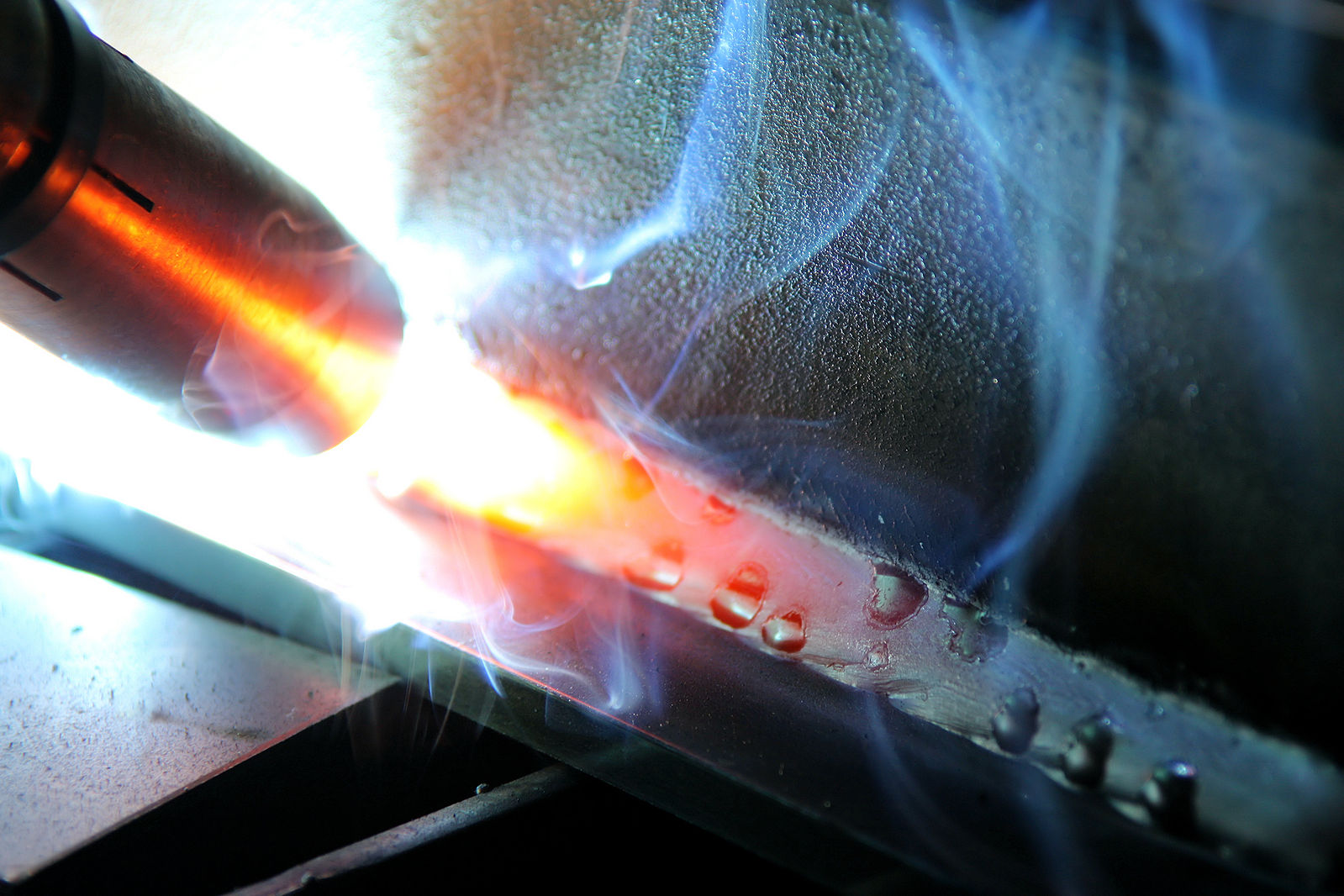
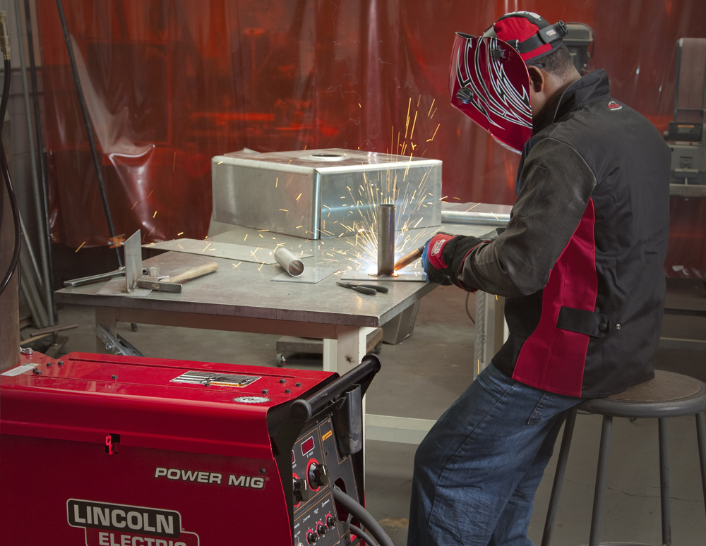
- Figure 10.19: GMAW application by Mgschuler is released under CC BY 3.0
In GMAW, transfer modes are the different behavioral changes in how electrode wire melts and gets transferred to the base metal. Transfer modes are controlled by the operator or welder, changing the relationship between wire and heat, write types, sizes, and shielding gasses.
Spray transfer refers to the behavior in which the wire from the welding machine melts at the tip and deposits into the joint so as to create fine droplets that are equal or less than the diameter of the electrode wire being used.
Transition current is the minimum current setting for the welding machine to transition from globular transfer and into spray transfer.
Plused spray transfer allows the current to toggle between a preset high current and down to a preset low current.
When the wire electrode connects to the weld puddle and creates a literal short in the circuit, as many as 200 times per second.
Globular transfer mode is named such because of how the wire melts off the end of the consumable wire. As the welding wire melts, it forms a large glob like droplet that are 2-3xs the size of the wire diameter.
When the weld current is high in relation to the voltage being set low, resulting in the welding arc 'burying' into the puddle resulting in a deeper penetration
