12.3 OFC Equipment and Setup
Karl Fulton
Components
Regulators
In order to work with the gas in the high-pressure cylinders, you must first reduce the pressure to a working pressure by utilizing pressure regulators. The regulator will control the release of pressure and flow or volume of gas per hour.
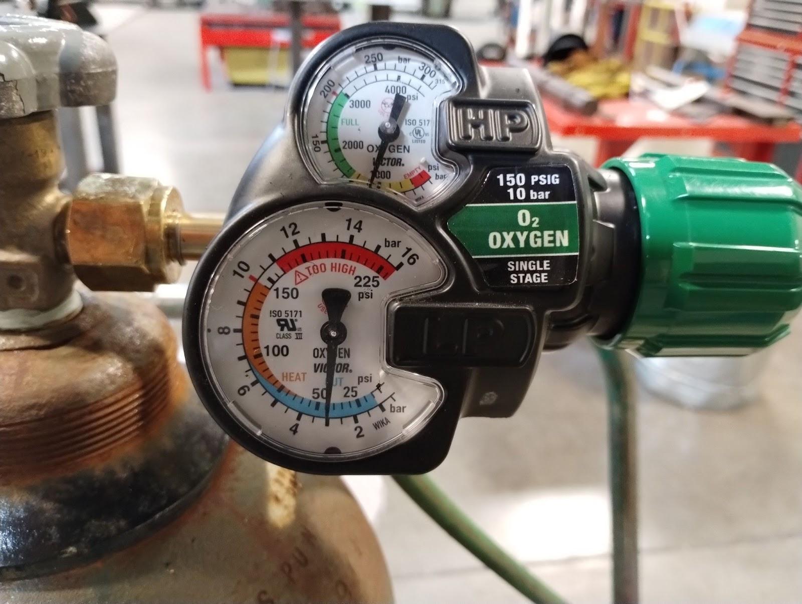
The typical regulator will have two gauges: a high-pressure gauge to indicate the pressure in the bottle as well as a gauge to indicate the pressure and flow of gas. These will both read zero psig (pounds per square inch gauge) until the bottle is opened and the regulator is adjusted to the desired pressure. If the bottle valve is open and the cylinder pressure gauge still reads zero, this does not mean the cylinder is empty; the pressure in the cylinder is simply equal to the surrounding atmosphere, meaning there are still gasses in the cylinder.
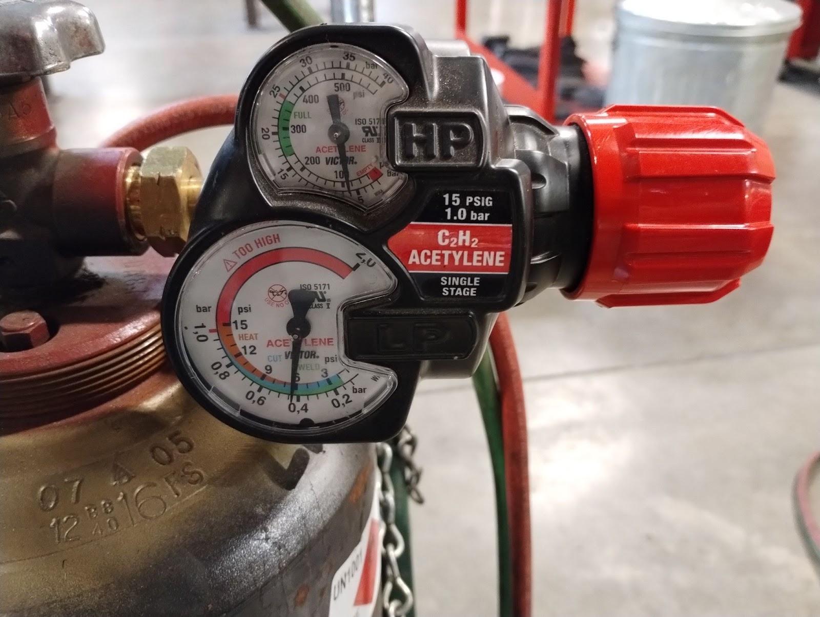
A fuel gas regulator and an oxygen regulator are almost exactly the same, but the fuel gas regulators are not designed to handle the extreme pressure from the oxygen bottle. Do not use either regulator for any other purpose. Regulators should only be used according to the manufacturer’s recommendations.
The two types of regulators are single-stage and double-stage. A single-stage regulator will reduce the pressure from the cylinder to the desired working pressure in a single step. The internal workings of the regulator that achieve this are a nozzle for the gasses to pass through, a valve seat to close off the nozzle, a diaphragm, and a balancing spring.
Oxygen enters the regulator and passes through a glass wool filter to remove dust and debris. To adjust the working pressure on the regulator, you tune the adjusting screw clockwise, allowing oxygen to pass from the high-pressure chamber to the low-pressure chamber and out the hose to your torch. The more the adjusting screw is tightened or turned in the clockwise direction, the more the working pressure will increase. Backing the adjusting screw off or turning in the counterclockwise direction will reduce the working pressure. When lowering the pressure, you must open the oxygen valve on the torch to get a correct reading on the low pressure side of the regulator. The high-pressure regulator shown in Figure 12.5 is gradated from 0–4,000 psig and from 0–225 psig. The high-pressure gradation on these regulators will stay pretty consistent. However, the low-pressure or working-pressure side of the regulator will vary depending on the type of regulator used. Some could be gradated from as low as 0–80 psig while others may be much higher, such as 0–400 psig for heavy cutting requirements. They will all be calibrated to read correctly at 70 degrees Fahrenheit.
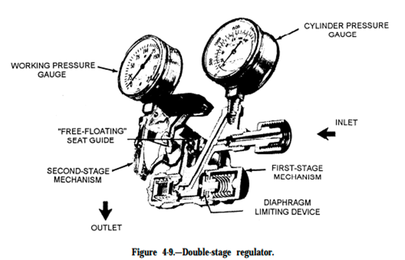
A challenge when working with single-stage regulators is maintaining consistent working pressure as the cylinder pressure drops. You may have to adjust the working pressure on the regulator because having a consistent pressure release from a cylinder that goes from 2,200 psig to 5 psig in one step is not feasible. The double-stage regulator is designed to mitigate this problem by reducing the pressure in two steps, or stages. The first stage is a predetermined pressure set by the manufacturer. Then in the second stage the pressure is reduced further to the desired working pressure you set, which results in a more consistent flow.
Hoses and Hose Connections
The hoses you use will be color coordinated: green for oxygen and red for fuel. These hoses can vary in size and length depending on the size of your torch system. If you are working in a small shop, you will probably only need 25 feet of hose to get around. But if you are working in a ship, you might have a portable cart that has 150 feet of hose so you can go down three deck levels without having to bring both cylinders with you.
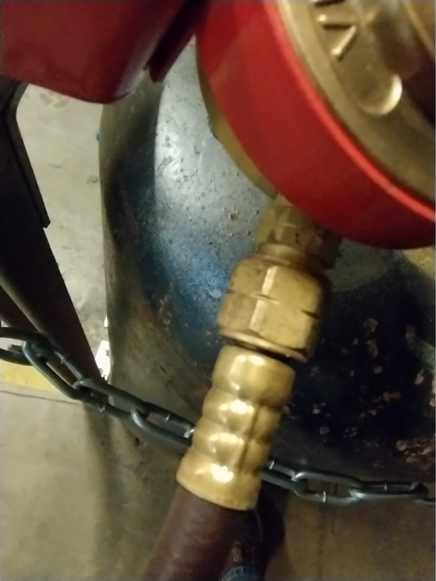
Additional safety features include left-hand thread connections on the fuel hose, making it impossible to connect to the oxygen. This will be denoted by hash marks or notches going around the nuts (see Figure 12.8).
Flashback arrestors should always be used on hoses for safety to prevent flames from back-feeding into the cylinder. Watch a video on flashback arrestors and how they work.
Torch Body
Torch bodies for OFC come in various sizes and combinations. Some torches are to be used exclusively as a cutting torch, and some will have attachments you can change out for welding, heating, and cutting. There are two needle valves on the torch: one for oxygen and one for fuel. Needle valves should never be over-tightened, as that can cause damage and limit your ability to adjust the flame settings.
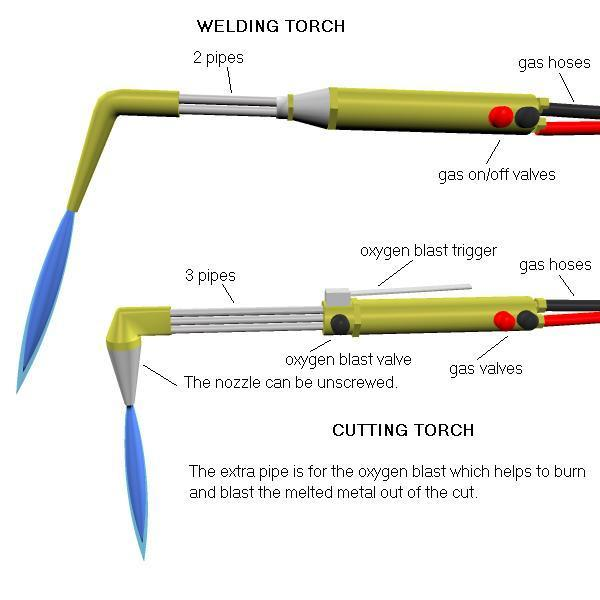
All torches will have a variety of tip sizes you can use depending on the thickness of the material you are cutting, welding, or heating. There is a common numbering system where the higher the number, the higher the heating capacity. For example, a tip size 1 has less heating potential than a tip size 2, and a size 00 has less heating potential than a size 0.
Refer to the manufacturer’s guidelines for selecting the right tip size, fuel, and oxygen pressures for the material thickness you are working with. They should have a tip chart that will tell you the size of the tip for the thickness of the material and the appropriate oxygen and fuel settings to use. An example tip chart is the Victor Acetylene Cutting Tip Chart from Eureka Oxygen Co.
There are other torch attachments worth mentioning. These include:
- Welding tips: They have a single hole designed to focus the heat on your material. They come in a variety of sizes and can be used for welding and brazing work.
- Rose bud: This is an attachment that create a a large flame with multiple holes to spread the heat out. It is used to preheat material, or even heat straighten material. It is possible to anneal aluminum with this attachment by first using a carburizing flame to put a layer of black soot on the aluminum, then using a neutral flame to burn off the soot, and then letting the aluminum air cool. The burning/disappearance of the soot gives you an indication that you have gotten the aluminum hot enough to anneal.
OFC Flame Types
Knowing the types of flames involved in OFC is very important for proper operation. There are three types of flame that you must get used to recognizing so you can make the proper adjustments while working with this process.
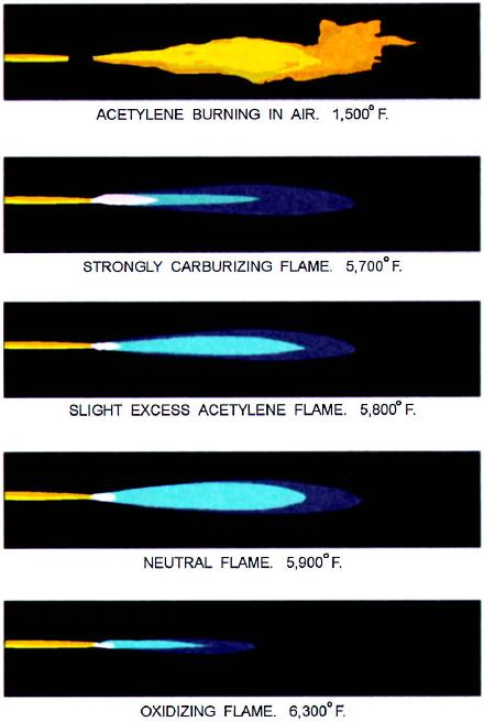
Carburizing flame occurs when you have an excessive amount of acetylene compared to oxygen. If you have a carburizing flame, you will be able to see a long feather cone in the middle of the flame, and the rest of the flame will be bright orange. The flame will give off lots of smoke and soot.
Neutral flame is the type of flame that you want to achieve when working with the OFC process. The inner cone appears as a small point at the tip of your torch, indicating you have a good balance of fuel and oxygen. There will be a distinct time when the inner cone stops shrinking. The inner cone will also be a vibrant, bright blue color.
Oxidizing flame occurs you have an excessive amount of oxygen compared to acetylene. If you continue to add oxygen after the inner cone stops shrinking, the cone will get sharper and a little dimmer than it appears as a neutral flame. It’s important to learn to recognize this as you set up your torch. To return to a neutral flame from an oxidizing flame, reduce the amount of oxygen or add more fuel.
Setting Up the System
Let’s review the steps to set up the system for OFC.
Attaching Regulators
First, inspect the opening on the oxygen cylinder valve and remove any debris that may be inside with a lint-free rag. Crack the valve open on the oxygen cylinder—making sure the opening is facing away from you and anyone else—to blow out any debris you may not have been able to get or see. Then attach the regulator, tightening it by hand first and then using a wrench to add a quarter turn. Do not over-tighten. Slowly open the oxygen all the way. (This is for a double-stage valve.)
Next, attach the acetylene regulator, which will have left-handed threads. Use your hands to tighten it, then add a quarter turn using a wrench. Slowly open the acetylene cylinder a quarter turn or until you get a strong reading on the bottle pressure gauge.
Once the cylinders are attached and open, turn the regulators clockwise to adjust the working pressure. Once this is reached, you can check all hose connections for leaks by spraying the fittings with some soapy water. Look for bubbles in the soapy water to identify leaks. If you see a leak, first try slightly tightening the regulator with a wrench, then perform the soapy water test again. If this does not work and there is still indication of a leak, fully shut off the valves, remove the regulator, and it check for defects.
Close needle valves using the tips of your fingers. Do not over-tighten the valves! This can cause damage to the small needle valves in the torch and lead to frustration later.
Lighting the Flame
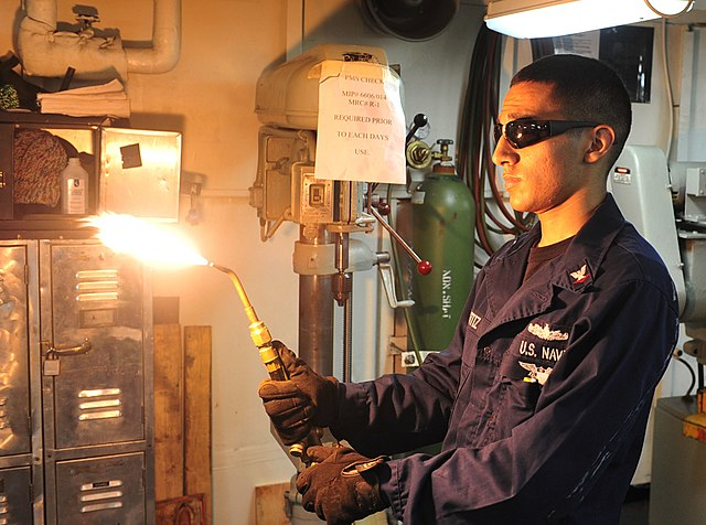
Begin by opening the fuel valve on the torch. You just want to crack this and then, using your friction igniter, light the torch. Add fuel until you have a strong, feathery flame similar to the one shown in Figure 12.11.
Achieving a Neutral Flame
Next comes adding oxygen until you get a neutral flame. Squeeze the lever on the torch to open the oxygen-cutting jet. Your preheat cones should not change as you do this. Then you can adjust the fuel and oxygen valves as your cutting jet is open to bring it to a neutral flame.
Inspect the flame for inconsistencies, which would indicate a dirty tip. If needed, shut down the torch and clean the tip. For this step, you would only need to shut down the torch and not the complete system.
Once you achieve a neutral flame, you can begin cutting the metal you’re working with.
Shutting Down
When you have finished cutting, be sure to follow safety guidelines and shut down your system properly. Turn off the fuel valve on the torch first, then turn off the oxygen valve on the torch. Do not over-tighten to keep your torch clean and reduce future issues—otherwise, soot will blow out.
If you suspect you have a sustained backfire in the torch (you can no longer see the flame, but the torch is making a noise), turn off the oxygen and then fuel. Remove the cutting tip and clean it before lighting again.
To review:
- Once the torch is off, turn off both cylinder valves.
- Open both the oxygen and fuel valves to bleed off the lines.
- Once both gauges on the regulator read zero, back off the regulators until they feel loose.
- Store the torch and hose neatly, using wide circular loops on the hose to avoid kinks.
Attributions
- Figure 12.5: Oxygen Regulator by Karl Fulton, for WA Open ProfTech, © SBCTC, CC BY 4.0
- Figure 12.6: Acetylene Regulator by Karl Fulton, for WA Open ProfTech, © SBCTC, CC BY 4.0
- Figure 12.7: Double-stage regulator by Naval Education and Training Professional Development and Technology Center in the Public Domain; United States government work
- Figure 12.8: Nut with notches by Karl Fulton, for WA Open ProfTech, © SBCTC, CC BY 4.0
- Figure 12.9: Types of gas torch head by Anthony Appleyard is released under CC0
- Figure 12.10: Characteristics of the oxyacetylene flame by Naval Education and Training Professional Development and Technology Center in the Public Domain; United States government work
- Figure 12.11: US Navy 111106-N-EZ913-299 Sailor ignites an acetylene torch aboard aircraft carrier USS John C. Stennis by Mass Communication Specialist 3rd Class Dugan Flynn in the Public Domain; United States government work
Reduces operating pressure in two steps
Black residue left behind from acetylene that hasn’t completely burned.
Excessive fuel, cooler burning.
Proper balance of gas and oxygen producing a clean burning flame.
Excessive oxygen, too hot
Continuous burning of gasses inside the torch.
