14.1 History of PAC
Karl Fulton
Development of PAC
The PAC process was developed in the 1950s as a method for cutting stainless steel. Tungsten inert gas welding had already been developed to weld exotic metals, then Robert Gage experimented with tungsten inert gas welding, which was already in application for welding exotic metals at the time, by constricting the arc and increasing the flow of gas. The result was that the arc had enough heat and momentum to cut through metals. Robert received a patent for the process in 1957 (Giles, 2022).
In the early days of its application, the PAC process did not reliably produce high-quality cuts. It was also only used for cutting stainless steel, which comprises a small section of the market. To compete with other processes, it would need to be a legitimate option for cutting carbon steel and produce high-quality cuts.
Even with its disadvantages, PAC was attractive because it offered much faster cut speeds compared to those of oxy-fuel cutting (OFC, discussed in Chapter 12). In the late 1960s, companies began researching ways to improve this process. Other needed improvements that researchers identified were the process’ cut consistency and improving its consumable life. Compressed oxygen was used to increase the speed and quality of cuts when cutting carbon steel, but this reduced its consumable life.
Then in the 1980s major advancements were made with the use of handheld torches, the utilization of compressed air, and the elimination of the need for high-frequency starting. These advances greatly reduced the overall weight of the PAC system, bringing it to its position in the industry today. And in the last 10 years companies have continued to improve the process’ cut quality, consumable life, and versatility.
Basics of the Process
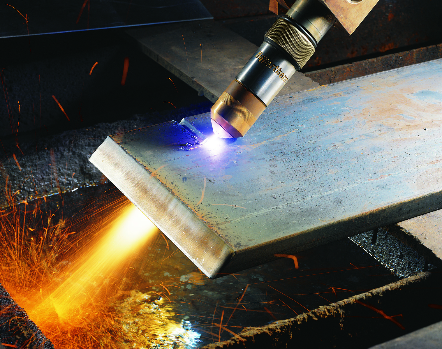
Similar to the arc welding processes, PAC involves the use of a power source, torch, shielding gas, and ground. The electric arc and shielding gasses are constricted through an orifice to create a plasma that can range in temperature from 18,000 degrees Fahrenheit to 40,000 degrees Fahrenheit. This flow of gasses shape the arc/plasma and blow away the molten metal, leaving a clean-cut edge with minimum dross.
This process is highly effective at cutting electrically conductive metals, the most common one being carbon steel, stainless steel, and aluminum. PAC is one of the fastest ways to cut materials between 0.25 inches and 2 inches thick. A lower-end plasma cutter can cut up to 0.6875 inches while the higher end models can cut up to 2 inches. Industrial-grade high-amperage machines have the ability to cut upward of 6 inches of material.
A PAC machine is also capable of piercing, gouging, and beveling pipe or plate.
Advantages of PAC include:
- Fast cut speeds and good cut quality
- Little to no prep work
- No preheat required to start
- Low heat affected zone and reduced distortion
- Ability to cut any conductive metal (carbon steel, stainless steel, aluminum, copper)
- Very little secondary work, such as post-cut grinding
- Minimal maintenance required
Disadvantages of PAC include:
- Initial costs are more expensive than OFC
- Must have an electrical source
- Must have air compressor or compressed gasses
- Fumes from the material being cut may be hazardous
What is Plasma?
Typically as you increase the energy in a matter, it changes states. For instance, when you heat ice it will turn to water and as you continue to heat the water it will turn to steam—turning from solid, to liquid, to gas states. Plasma, however, cannot be characterized as a solid, liquid, or gas. So what is it?

Plasma is the fourth state of matter. Think about lightning, a naturally occurring form of plasma. It can’t be a solid, as it has no melting point and doesn’t hold a shape. It has no surface tension and no boiling point, so it is not a liquid. It is not a gas because you can’t capture a sample of plasma and put it in a cylinder. Therefore, it is plasma.
As plasma molecules are breaking down, they are heated to a point beyond being a gas. The typical characteristics of plasma are bright emitting light energy and very high radiating thermal energy.
Some common places you can see plasma are in fluorescent bulbs, neon lights, and plasma TVs.

A star is a giant ball of plasma held together by its own gravity.

Another example of plasma is the phenomenon of auroras. They are solar winds from the sun iterating with the magnetic field of the earth and impacting gas molecules in the atmosphere.
You will also see plasma during any arc welding process, as the arc is plasma. The difference with PAC from other processes is that the arc/plasma is constricted. Electrons flow from the hafnium electrode and collide with neutral gas molecules. These collisions free more electrons and create positively charged molecules, or ions. This creates a cascading column of collisions, radiating heat and bright light. The swirling gas in the torch centers the plasma on the electrode and pushes it out of the nozzle to be used to cut, gouge, or shape metal.
Uses of PAC in Industry Today
There are a wide variety of industries that use PAC. However, there are two different categories of PAC to be considered: handheld plasma cutting and mechanized plasma cutting.
Handheld Plasma System
These are some examples of how ar handheld plasma system are used in industry:
- General fabrication, food processing equipment, tank fabrication
- Facility, railway, and sawmill maintenance
- Shipbuilding and shipyards
- Container fabrication and repair
- Vehicle repair and restoration (removing floor panels and exhaust and bracket removal)
- Agricultural equipment repair
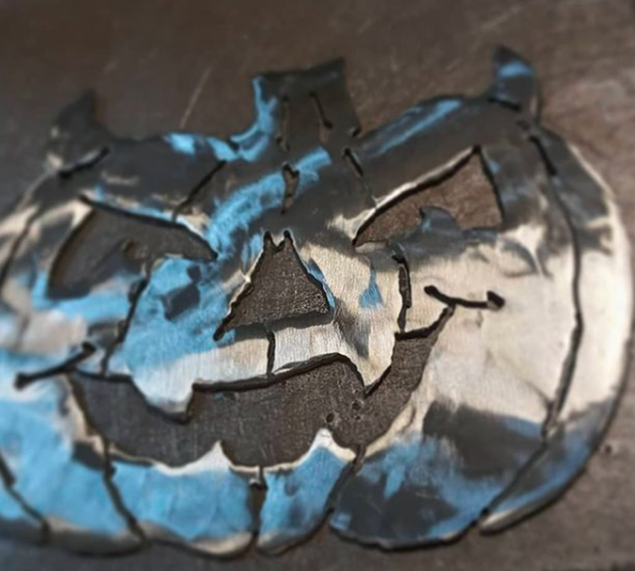
- Ornamental fabrication (artwork)
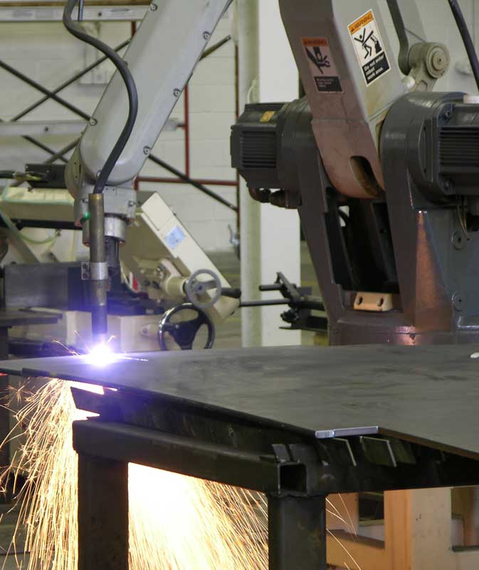
Mechanized Plasma System
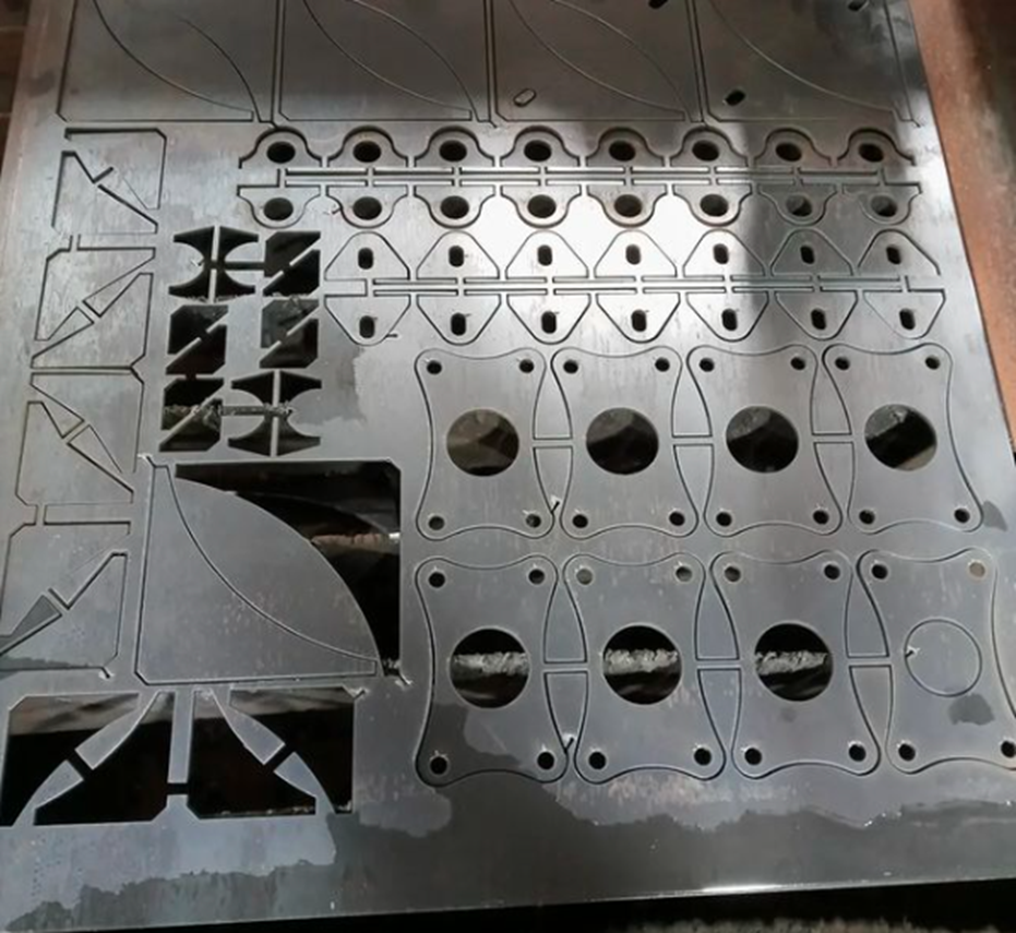
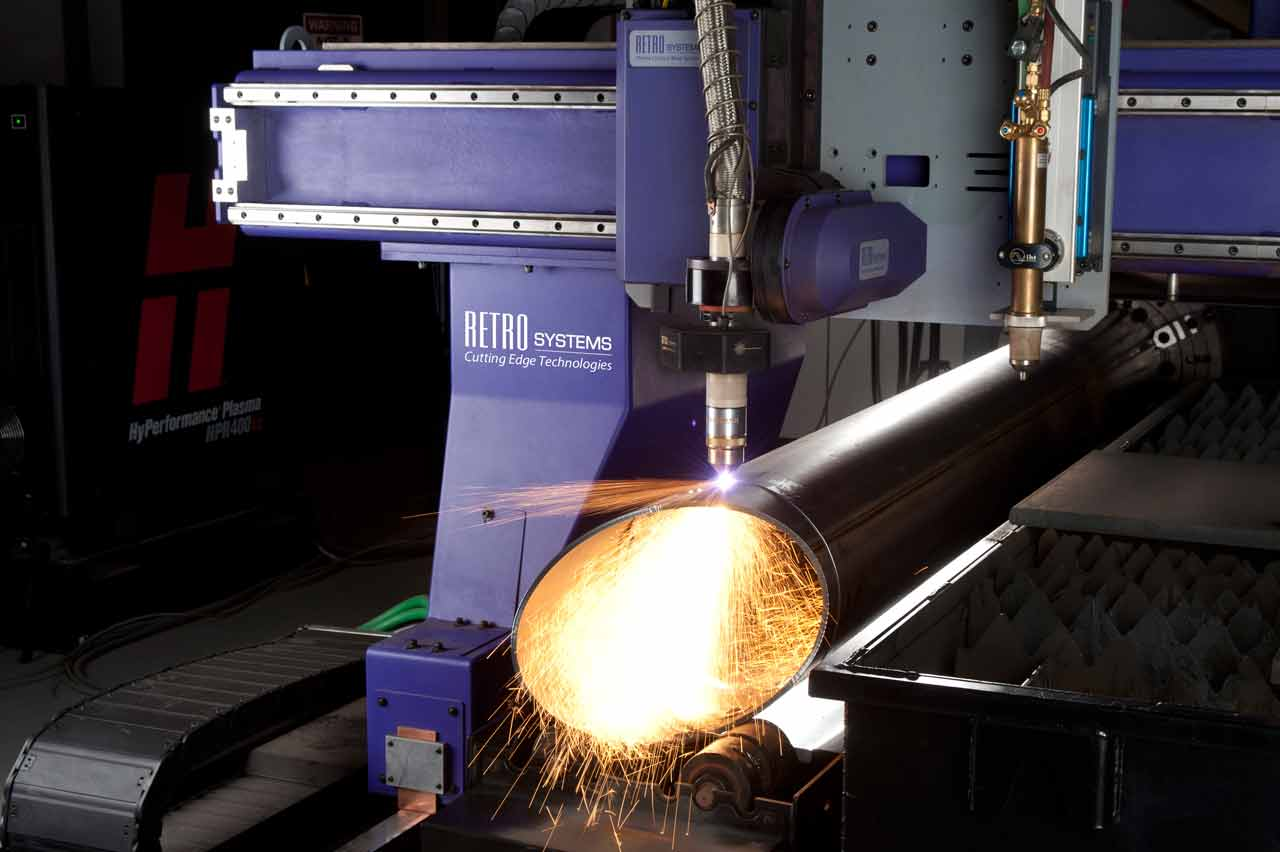
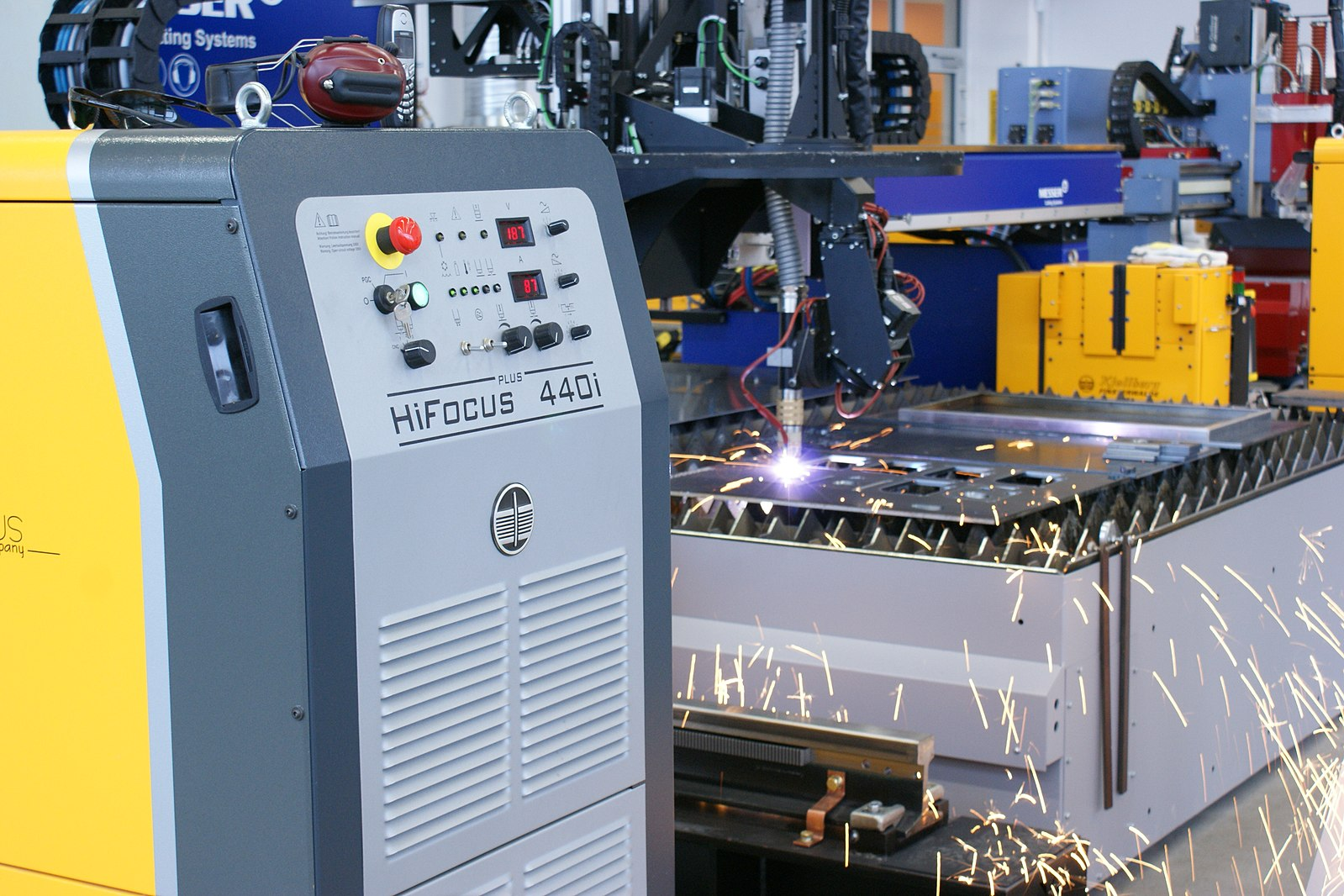
It’s important to note that mechanized plasma systems can be used for a wider range of material thicknesses. These machines can range from less than 45 amps to over 400 amps. Another advantage of mechanization is it can be used to produce repeatable parts with a very close tolerance. This is normally done on a table with an x-axis and y-axis, on a pipe beveler, or with a robotic arm.
These are some examples of how a mechanized plasma system are used in industry:
- Fabrication shops
- Heavy equipment manufacturing for agriculture or construction
- Vehicle fabrication
- Ship or submarine building
- Production shop that fills orders on cut parts
Attributions
- Figure 14.3: image released under the Pexels License
- Figure 14.4: OPEN by makou0629 is released under CC BY 2.0
- Figure 14.5: C3-class Solar Flare Erupts on Sept. 8, 2010 [Full Disk] by NASA Goddard Space Flight Center in the Public Domain; United States government work
- Figure 14.6: TorchCuttingCloseup by Hypertherm in the Public Domain; Public Domain dedication, not CC0
- Figure 14.7: Pumpkin by Karl Fulton, for WA Open ProfTech, © SBCTC, CC BY 4.0
- Figure 14.8: Parts Cut on CNC Plasma Table by Karl Fulton, for WA Open ProfTech, © SBCTC, CC BY 4.0
- Figure 14.9: Robotworx-plasma-cutting-robot by Robotworx is released under CC BY 3.0
- Figure 14.10: Retro Systems CNC Pipe Combo System by Steve Brown Photography is released under CC BY 3.0
- Figure 14.11: Plasmaschneidanlage-im-Einsatz by Kjellberg Finsterwalde is released under CC BY 3.0
A gas heated by an arc to at least a partially inonized condition, enabling it to conduct electric current. Ref AWS A3.0M/A3.0:2020. Standard Welding Terms and Definitions.
Unwanted byproduct of molten metal, this material can stick to the bottom the metal being cut.
