15.1 Weld Joints and Positions
Cameron Kjeldgaard
Weld Joints
A weld joint is the junction of two workpieces to be joined by welding (or, in some cases, by brazing). There are five basic joint types.
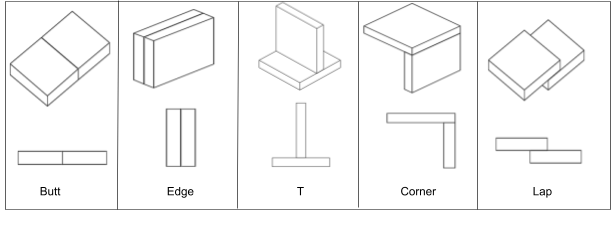
- Butt Joint: when two workpieces are butted against each other by their edges; their surfaces will typically lie in a common plane.
- Edge Joint: when the surfaces of two workpieces are joined in parallel and their edges lie in a nearly common plane. Welding takes place at the junction of the two edges.
- T Joint: when the edge of one workpiece abuts the surface of the other, creating a T shape. It is most common for the workpieces to be in a perpendicular arrangement, but in some cases the abutting member may be skewed at an angle, referred to as a skewed T joint.
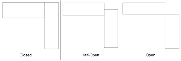
- Corner Joint: when two workpieces form an L shape. There are three possible configurations for a corner joint. In an open corner joint the edges of the workpieces do not overlap at all. In a closed corner joint (sometimes called flush) the surface of one workpiece completely overlaps the edge of the other. And in a half-open corner joint the surface of one workpiece only partially overlaps the edge of the other (see Figure 15.2).
- Lap Joint: a configuration in which the surfaces of the two workpieces overlap, though not fully as in an edge joint, and neither of their edges abut the other.
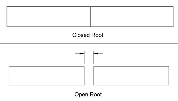
Depending on the type of weld applied at the joints, there are different terms and measurements used to describe specific parts of the joint and resulting weld. However, all welded joints share a common feature that is of particular importance to the welder: the joint root.
The joint root is defined as that portion of the weld joint in which the two workpieces come in closest proximity to one another. Weld size—and, by proxy, weld quality—is often measured by the penetration of weld metal into the joint root. Many times the two workpieces are in physical contact at the joint root; these are called closed roots. However, sometimes workpieces are intentionally spaced apart at the joint root, and the linear measurement of the gap between the workpieces is called the root opening. Root openings permit deeper penetration of the weld metal into the joint root, increasing weld size and strength.
Welding Positions
Before our discussion of welding positions, let’s start with a brief explanation of why the welding position is a critical factor to consider.
The most commonly applied welding codes all require welding personnel to pass a welding qualification test prior to working on any project governed by that code. Once a welder passes that test, they are “certified” to weld under that code, although with certain limitations. Those limitations are often referred to as “essential variables.” That means if the conditions of production welding cause any of the essential variables to deviate significantly from the conditions of the original qualification test, then the welder is no longer covered by their certification to perform that production welding. What those variables are and how significantly they can be changed depends on the welding code, but often they include the welding process, the welding machine electrical settings, the base metal, and the welding position.
These limitations exist because significant changes to those variables would then lead to significant changes in required technique and skill level to complete the work. This may be truer for welding position than any of the other factors mentioned. A change in welding position has a cascading effect on travel speed, electrode angles, electrode manipulation, and welding machine electrical settings. Therefore, a welder qualification test provides coverage for the welder to perform production welding in that specific position. Sometimes, however, the same test also allows the welder to work in positions that are considered easier to weld in.
Now let’s cover the welding positions, which are defined by the American Welding Society (AWS). There are four basic welding positions, each with a number designation. Two more positions are specific to welding on round tube or piping.
AWS uses two factors to define welding positions. The first factor is the axis of the weld joint, which determines our direction of travel as we weld along the joint. The joint axis may have a horizontal orientation that is level with the world (see the 1F, 2F, and 4F positions shown in Figure 15.4)—in this case we would say the weld axis is horizontal.
The other factor to consider is the orientation of the weld face once welding is completed. The AWS defines the weld face as the “exposed surface of a weld on the side from which welding was done” (American Welding Society, 2010). In simpler terms, the weld face is the only part of the weld you can see when you’re done welding (in most cases). The face of the weld, while not perfectly flat, lies on a plane, and the orientation of that plane is the second factor in defining the weld position. As an example, consider welding positions 1F and 2F (see Figure 15.4). The orientation of the weld face in position 1F is what makes it a flat position weld even though the axis of the weld joint is horizontal like in position 2F.
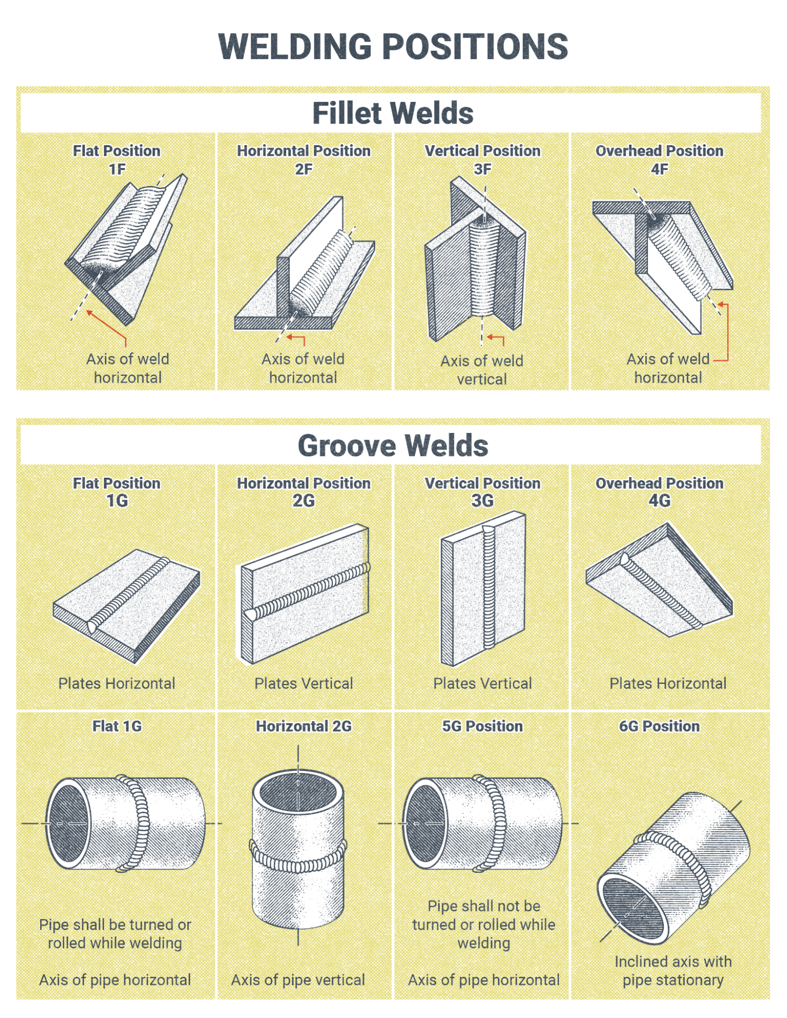
The four basic welding positions all take place on plate, where the weld joint is a straight line.
- The flat position is designated with the number 1. This is typically considered the easiest position to weld in, as gravity works in the welder’s favor rather than against them. The flat position also allows for faster welding speeds and higher amperage settings. The AWS definition of the flat position is: “The welding position used to weld from the upper side of the joint. . . where the weld axis is horizontal, and the weld face lies in an approximately horizontal plane” (American Welding Society, 2010, p. 19). Although the flat position is easiest and fastest, it is often impractical to position work, especially large assemblies, so welding can take place in the flat position.
- The horizontal position, designated with the number 2, is probably the position most commonly used for welding, and certification in horizontal position is a minimum prerequisite for many employers. Proper electrode angles and travel speed are essential to keep the molten weld puddle from sagging out of the joint when welding in this position. The AWS definition of the horizontal position is: “The welding position in which the weld face lies in an approximately vertical plane and the weld axis. . . is approximately horizontal” (American Welding Society, 2010, p. 23).
- The vertical position, designated with the number 3, takes significantly more operator skill than either the flat or horizontal positions. There is a higher likelihood of weld defects occurring in this position. The difference is stark enough that welding performed outside of horizontal or flat positions is sometimes colloquially referred to as “out of position” welding. The vertical position has a critical factor to consider: progression. The progression may be upward or downward, referred to as uphill or downhill, respectively. The technique used and the weld result from application of the two progressions are very different—so much so that progression is an essential variable of welder certification for this position. A vertical test taken with an uphill progression qualifies that welder in that progression only, and vice versa for a test taken with a downhill progression. The AWS defines vertical position as such: “The welding position in which the weld axis. . . is approximately vertical, and the weld face lies in an approximately vertical plane” (American Welding Society, 2010, p. 45).
- The overhead position is designated with the number 4, and in this case the orientation of the weld axis and weld face are the same as in the flat position. Like the vertical position, this one requires more operator skill than what is required for flat and horizontal positions. Because the welder is often positioned underneath the molten weld pool and showered with hot sparks and molten slag, proper personal protective equipment is critical when welding in the overhead position. A leather welding jacket with the collar and sleeves buttoned and a headcap to protect the welder’s hair and scalp from burns are necessary. The welder should take care to stand off to the side of the weld joint to mitigate the risk of burns. The AWS definition of the overhead position is: “The welding position in which welding is performed from the underside of the joint” (American Welding Society, 2010, p. 30).
As mentioned earlier, there are two additional positions for welding round tubes or piping; they are designated with the numbers 5 and 6. In pipe welding, the weld joint may run around the circumference of the pipe. In position 5 the length of the pipe is horizontal, putting the pipe’s circumference on a vertical plane. In this position, the welder essentially moves from overhead to vertical to flat positions as they progress around the circumference of the pipe, starting from the bottom. The situation is essentially the same in position 6 but the pipe is inclined to 45 degrees rather than horizontal. Welding qualification tests for positions 5 and 6 consider the diameter of the pipe as an essential variable, as smaller piping is more difficult to weld than larger piping.
Attributions
- Figure 15.1: Basic Joint Types by Cameron Kjeldgaard, for WA Open ProfTech, © SBCTC, CC BY 4.0
- Figure 15.2: Corner Joint Configurations by Cameron Kjeldgaard, for WA Open ProfTech, © SBCTC, CC BY 4.0
- Figure 15.3: Open vs. Closed Root by Cameron Kjeldgaard, for WA Open ProfTech, © SBCTC, CC BY 4.0
- Figure 15.4: Open vs. Closed Root by Nicholas Malara, for WA Open ProfTech, © SBCTC, CC BY 4.0
The junction of two workpieces that will be joined by welding.
The portion of the weld joint where the two members of the joint approach closest to each other, when viewed in cross-section the joint root may be a point, line, or area.
A typically deliberate spacing between the two members of the joint at the joint root.
The position of the weld joint to the welder. Typically flat, horizontal, vertical, and overhead. Positions at a 45 degree angle are also used for pipes because the welder will weld in the flat, horizontal, vertical, and overhead position as they make their way around the circumference of the pipe.
The axis on which the length of the weld joint lies.
the exposed surface of a weld.
