15.5 Resistance Welds
Cameron Kjeldgaard
Types of Resistance Welds
Resistance welding is fundamentally different from arc welding. In arc welding, the welder must control many factors to ensure a proper weld is deposited. Resistance welding, however, is usually accomplished by the press of a button since a machine, such as a seam or spot welder, does most of the work. Resistance welding is much less versatile than arc welding, but it is well suited to mass production in some manufacturing environments, and it takes much less training for welding personnel.
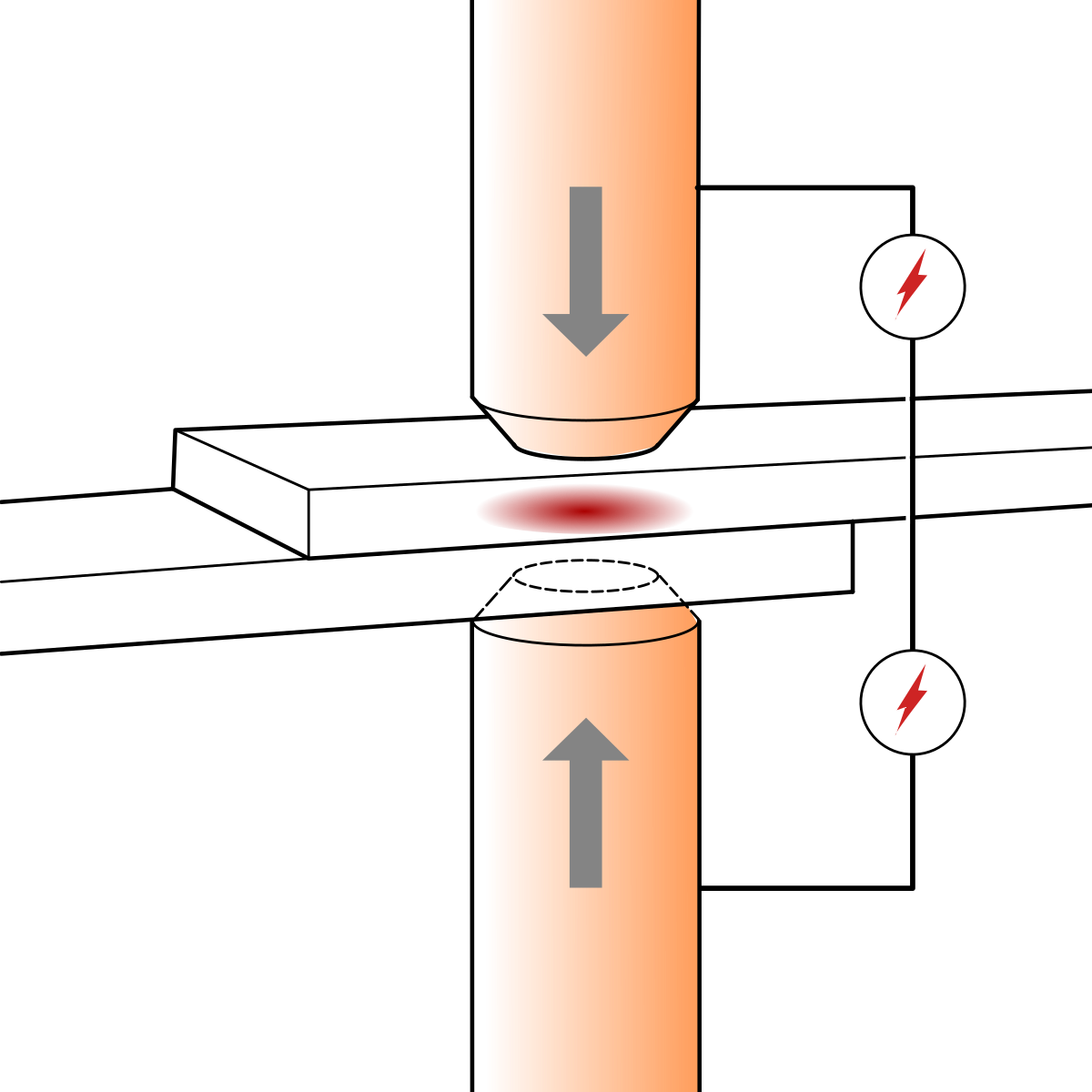
In arc welding, the welding circuit jumps an air gap, encountering an immense amount of electrical resistance, which creates the heat for welding. In resistance welding the heat is provided by the electrical resistance of the material itself. As shown in Figure 15.15, two pieces of material are placed into contact with one another, then two electrodes (positive and negative) are pressed into contact with the material. The welding current passes from one electrode, through the material and the weld joint, and into the other electrode to complete the welding circuit. Where the two pieces of material make contact with one another, between the electrodes, the most electrical resistance is created, which allows welding to occur. Because the material is more conductive than the air gap used in arc welding, much higher currents are used in resistance welding.
There are three ways resistance welding is typically accomplished: resistance spot welding, resistance seam welding, and projection welding.
Spot welding is the simplest form and is the type illustrated in the image at the opening of the chapter. In spot welding, the parts will be welded in a lap joint. The two electrodes will press on the outside of the joint and, as the welding current passes through, a small weld nugget will melt and fuse the two pieces at the interface of the parts between the electrodes.
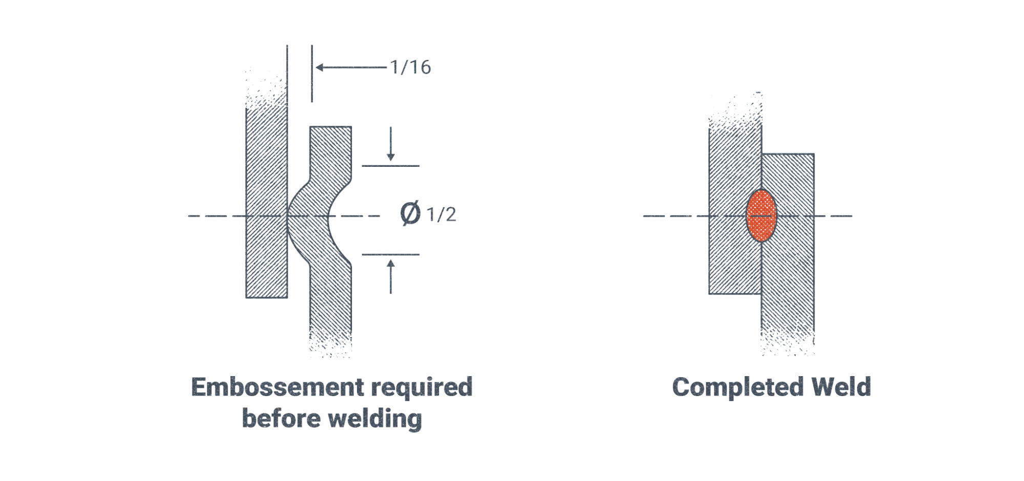
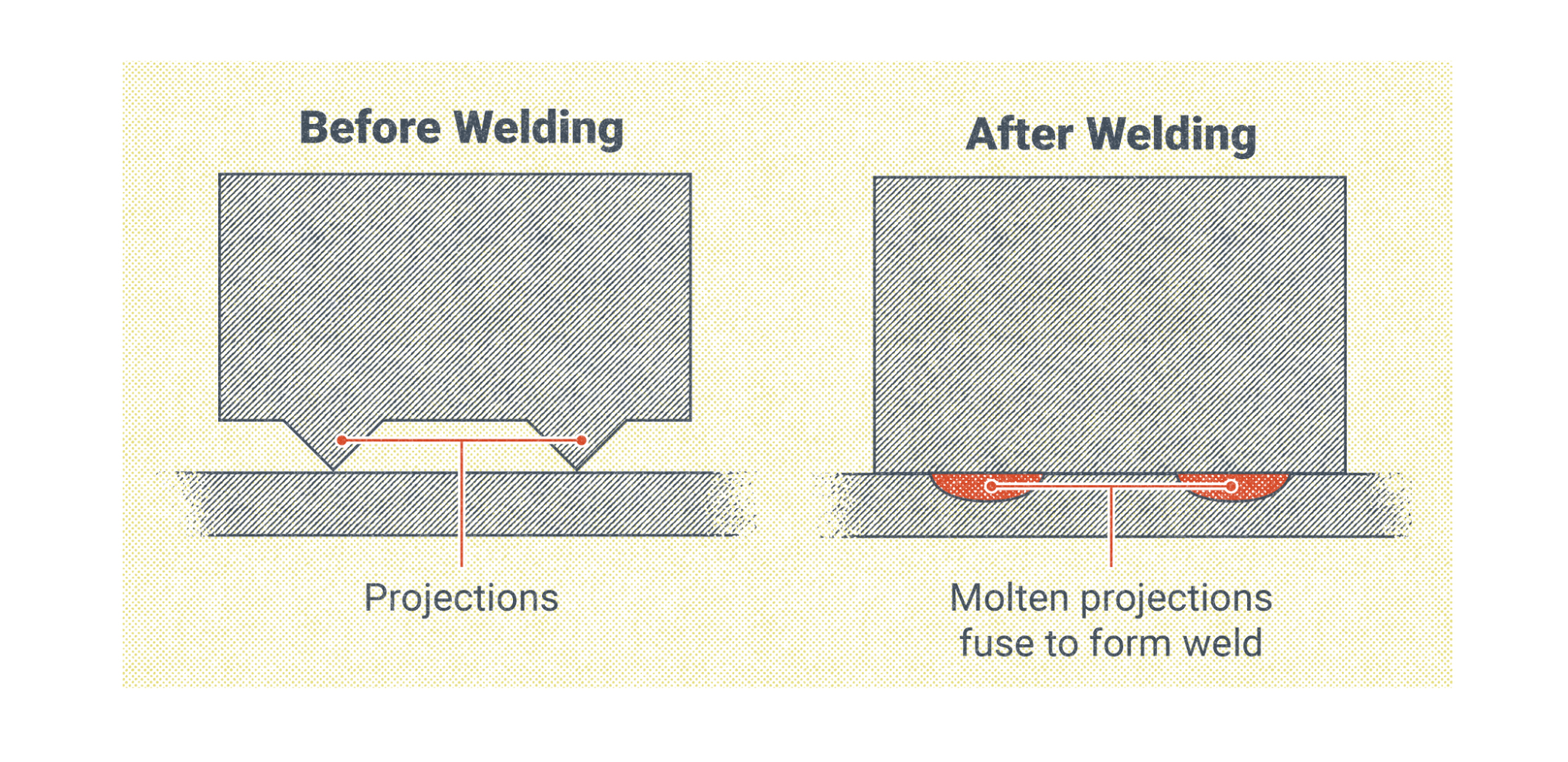
Projection welds are essentially the same as spot welds but involve more preparation of the material, as a small projection must be indented in one of the parts prior to welding. When welding occurs, this projection is heated and pressed into the other part by the resistance welding machine, ultimately fusing into the deposited weld nugget.
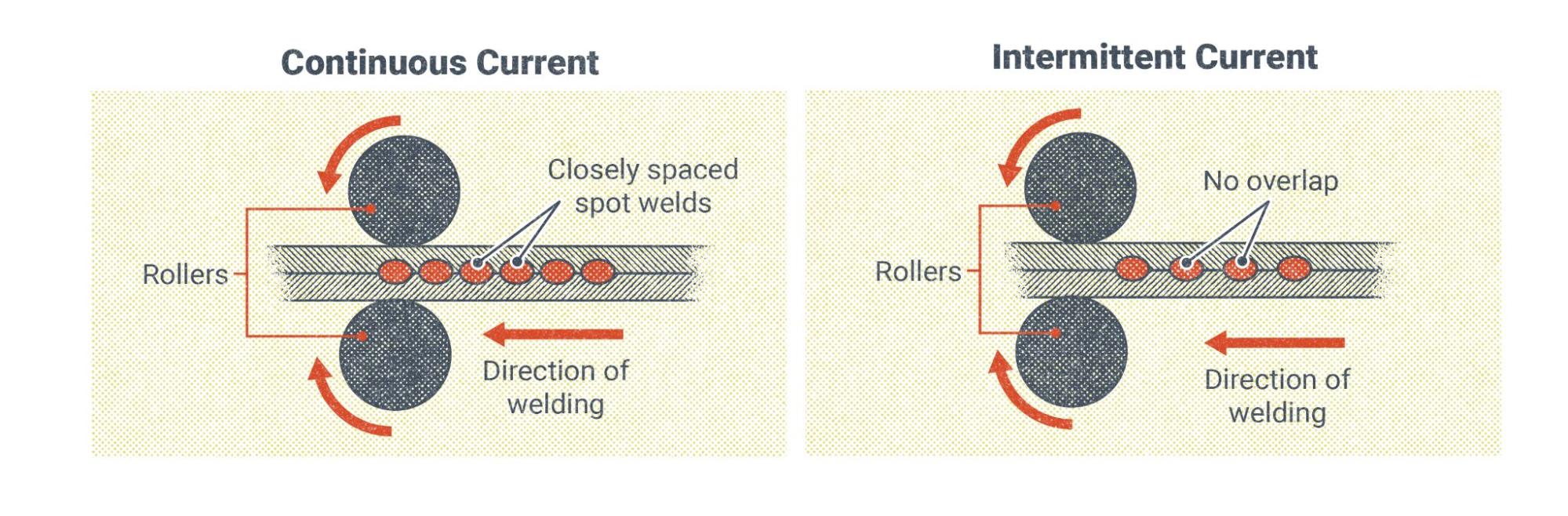
Seam welding is often used in steel manufacturing to produce parts that have long butt joints and require long continuous welds. The concept is the same as in resistance spot welding, only the nuggets of weld metal produced by resistance welding are placed much more closely together, or even overlapping each other. To accomplish this weld, a seam welding machine will usually use electrodes that can roll across the material, allowing constant transmission of the welding current even while the material is moving through the machine.
Resistance Weld Sizing
The size of resistance welds is measured by the diameter of the weld nugget left behind after welding. This size is directly related to the amount of current used and the amount of time that current flows through the electrodes and material.
However, weld diameter is not the only factor to consider when calculating the strength of the weld joint. In the case of spot and projection welds, the amount and spacing of individual welds are also used t. This is true for seam welding too, although when the weld nuggets overlap, as is often the case, the strength of the weld metal should be the same as the base metal.
Attributions
- Figure 15.15: Punktsvetsning by Kavelgrisen is released under CC BY-SA 4.0
- Figure 15.16: Before And After Of A Projection Weld by Nicholas Malara, for WA Open ProfTech, © SBCTC, CC BY 4.0
- Figure 15.17: Another Example Of Before And After Of A Projection Weld by Nicholas Malara, for WA Open ProfTech, © SBCTC, CC BY 4.0
- Figure 15.18: Process For Seam Welding by Nicholas Malara, for WA Open ProfTech, © SBCTC, CC BY 4.0
A group of welding processes in which the heat for welding is provided by the electrical resistance of the materials being joined.
