16.2 Lines
Cameron Kjeldgaard
Lines are the simplest element of any print. The ability to distinguish between the different types of lines and identify their purpose is absolutely essential to interpreting any drawing. Some lines have very niche uses in specific industries or to particular individuals within an industry. We’ll cover the most common lines.
Lines on prints don’t follow the standard mathematical definition of a line as a straight, one-dimensional figure. Rather, lines serve a variety of purposes: some represent the physical edges of what is being made, some act as a reference point for different views, and some are used for dimensioning and measurement. With so many purposes, there must be a way to distinguish them; therefore, some lines are straight and solid while others are drawn irregularly or broken into a series of dashes. The thickness of a line, called the line weight, is also often significant, as a line may be fine, medium, or thick. Depending on the quality of the print and the detailing work that went into making it, line weights may a be more or less reliable way to differentiate between them.
Let’s review line types:
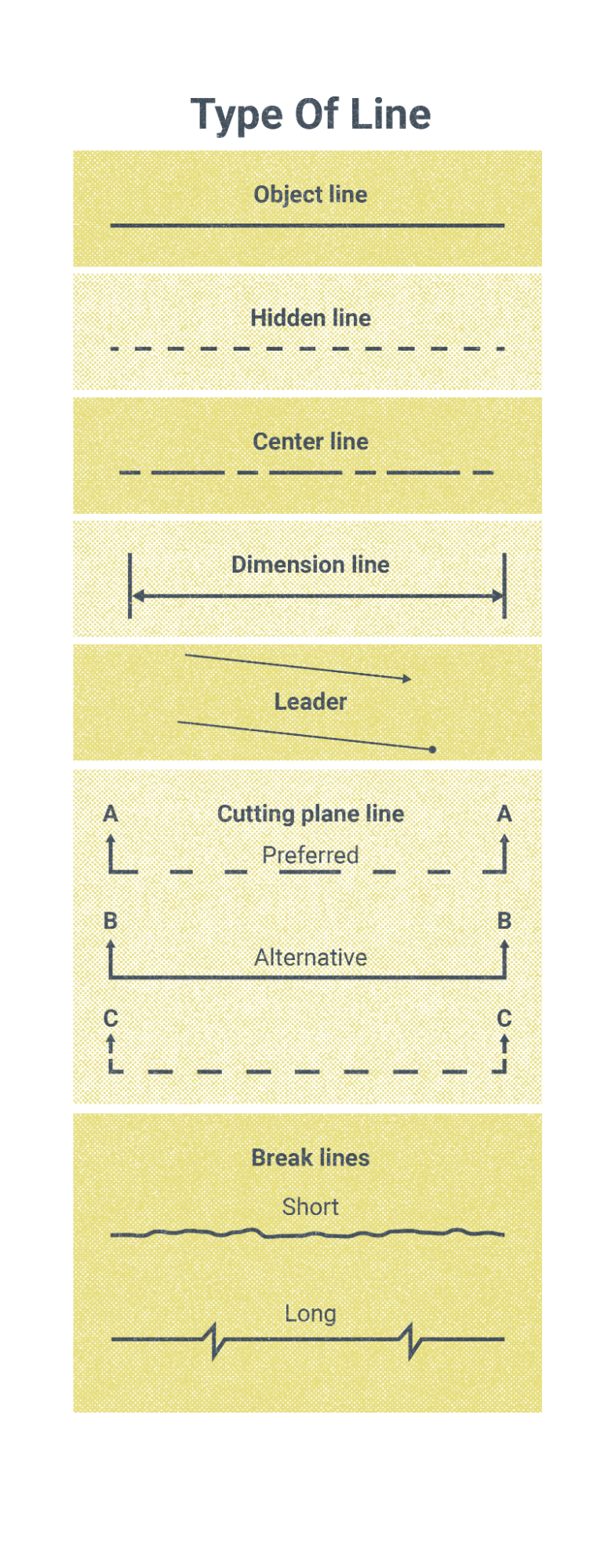
- An object line represents the physical edge of an object as it would be seen from the view presented in the drawing.
- A hidden line also represents the physical edge of an object, but one that would not be visible from the view presented in the drawing because it is obscured from view by another part of the object being shown.
- A phantom line is used to represent the different possible positions of any moving parts of an assembly.
- Extension lines show the reference points on the object for which dimensions are given. They are perpendicular to the dimension lines and may be longer or shorter in length to make good use of the space available on the print.
- Dimension lines end in arrows and connect to extension lines. They show the extent, or range, of a given dimension.
- Centerlines provide dimensional information about an object by showing the center of symmetrical objects, as well as circles, arcs, and radii. A centerline showing the center of any circular object may appear as a + sign, called a center mark.
- A leader line points to a specific part of the object being shown to either delineate its dimension or add a written note. The leader line will end in an arrow if referencing an edge, but a solid dot is used when referencing a surface.
- Both short break lines and long break lines are used to conserve space on a drawing. If there is some stretch of an object being built that doesn’t require attention from the fabricator, then there isn’t a need to show it on the print. The portion of the object omitted will be long or short, depending on the style of the line.
- A cutting plane line is used as a reference point to interpret a section view, with arrows indicating the perspective of the view and letters at either end of the cutting plane line marking the name of the related view. For example, a cutting plane line with A at either end would reference you to a view labeled A-A.
Attributions
- Figure 16.1: Various Types of Lines Used in Welding Blueprints by Nicholas Malara, for WA Open ProfTech, © SBCTC, CC BY 4.0
- Figure 16.2: Symbol for Centerline by Nicholas Malara, for WA Open ProfTech, © SBCTC, CC BY 4.0
The thickness of a line; most line weights are fine, medium, or thick.
