16.3 Views
Cameron Kjeldgaard
Base and Projected Views
An illustration of an object from a certain perspective is called a view. A view may be pictorial, showing a sort of three-dimensional view of an object from a corner perspective.
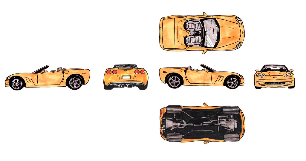
Most of the time drawings are shown on a print using a method called orthographic projection. This is a way of representing a three-dimensional object using two-dimensional drawings. There can be up to six views in a drawing like this (although three views—front, top, and right side—may be all that is needed) and they are always arranged in the same pattern, like an unfolded cube (see Figure 16.3. The front view, sometimes called the base view, is the primary view and the one from which the others project. It’s important to distinguish that what is shown in the front view may not actually be the front of the object shown; rather, that view is what the detailer or drafter chooses to show since it displays the greatest amount of relevant information and dimensions for fabricating the object.
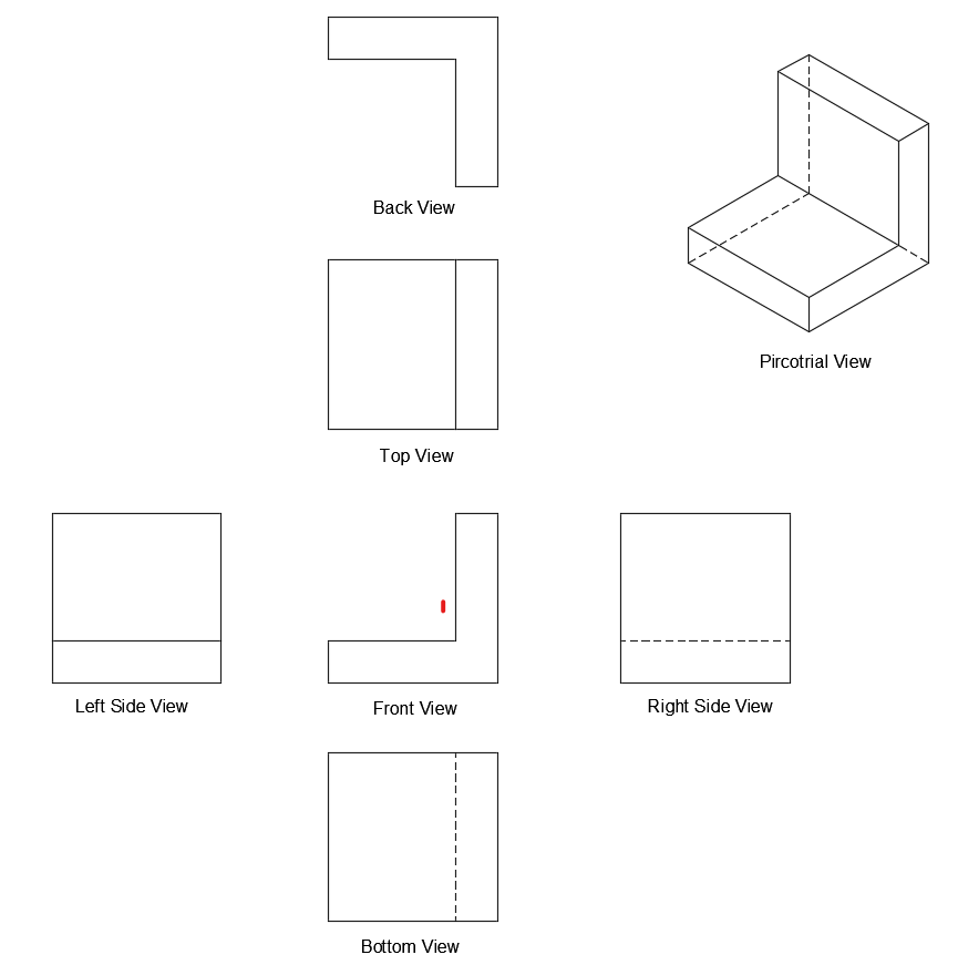
As shared above, the front view is always included in orthographic projections and the other views are based off of it. When one view projects to another, you must imagine it rotating a certain way. The L-shaped piece from the pictorial view in Figure 16.4 demonstrates this. Recall that the heavy solid lines are object lines representing visible edges and the dashed lines represent edges hidden from view; this is the clue to understanding how one view translates to another.
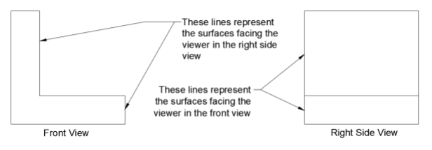
To demonstrate this further, take as another example a drawing with just two views: a front view and right side view. The right side view is, and always will be, located to the right hand of the front view (as in Figure 16.5). The object lines on the rightmost side of the front view represent the surfaces which face the viewer in the right side view. This same logic can be applied when the object rotates from the right side view back to the front view, or from the front view to any other.
Section Views
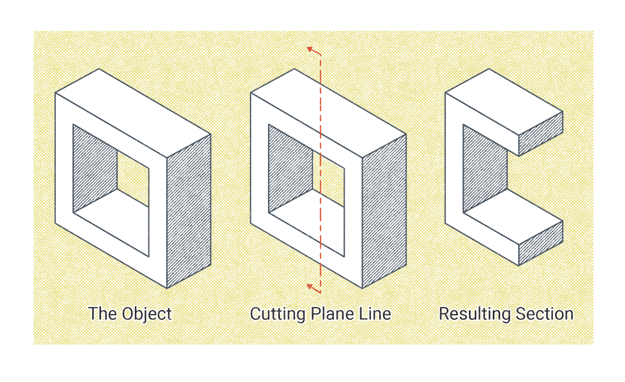
A section view is a special type of view that makes use of cutting plane lines. The cutting plane lines indicate where the section view originates and which direction the perspective of the view is facing.
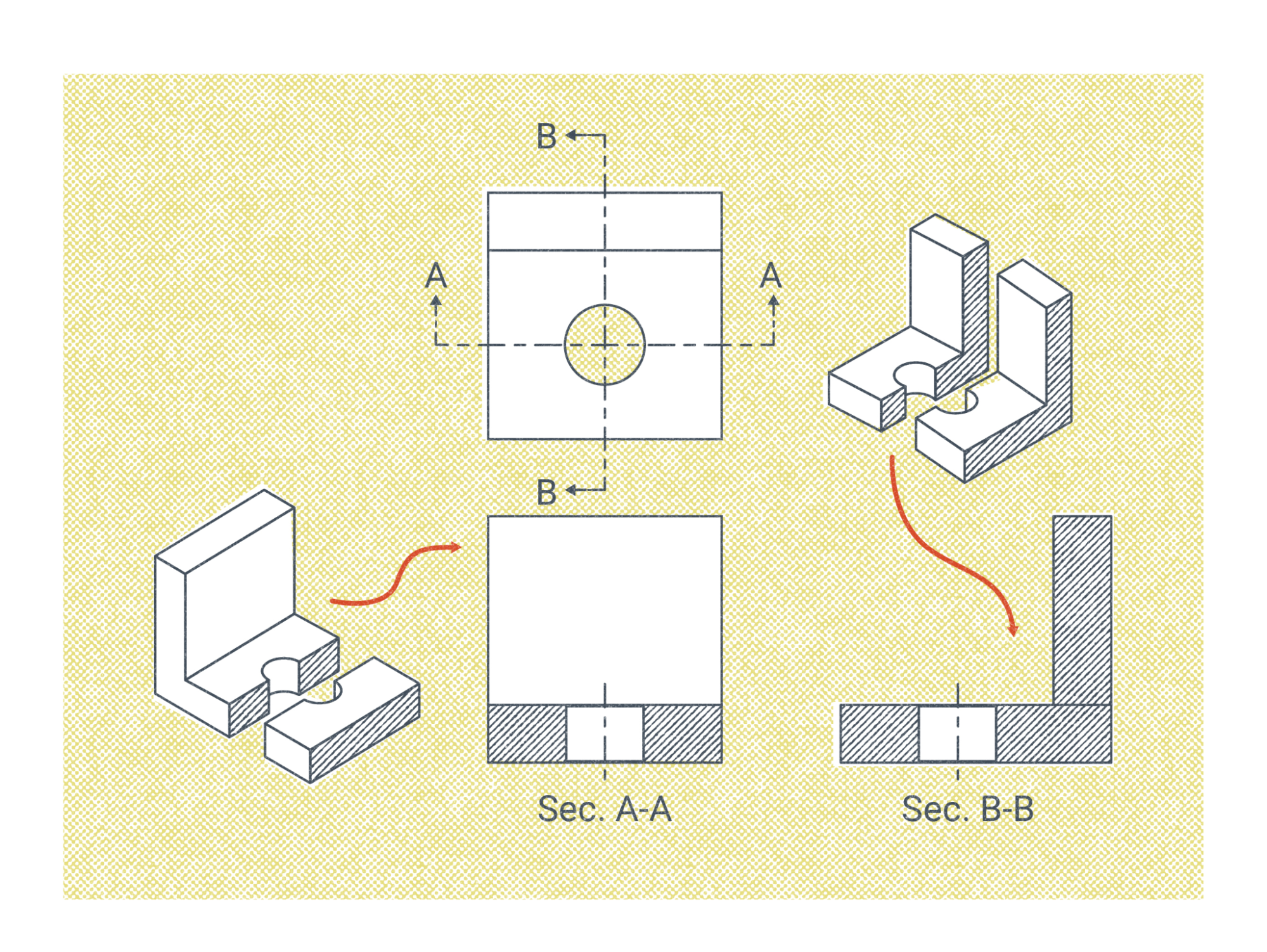
Often multiple section views are used. In some cases it is more common for a print to use a single base view with multiple section views, rather than the projected views. To keep track of multiple views, the cutting plane lines will have reference letters which appear below the resulting section view, as shown in Figure 16.7.
Detail Views
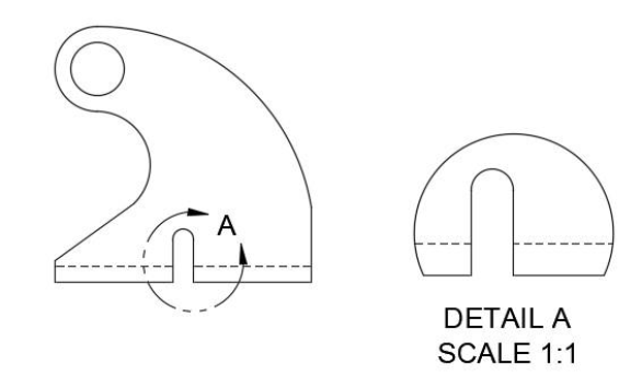
Detail views are used when a particular feature requires a lot of information to be properly fabricated and, as the name implies, provide particularly detailed information. These views are usually shown at an enlarged scale as compared to the rest of the drawing. As you can imagine, a small, complex feature on a large assembly cannot be properly detailed unless it is blown up in a detail view.
Much like section views, detail views use letters to reference the reader to the resulting view. But rather than using cutting plane lines, detail views use a circular reference line with a single letter to direct the reader to the resulting view, as shown in Figure 16.8.
Views With Break Lines
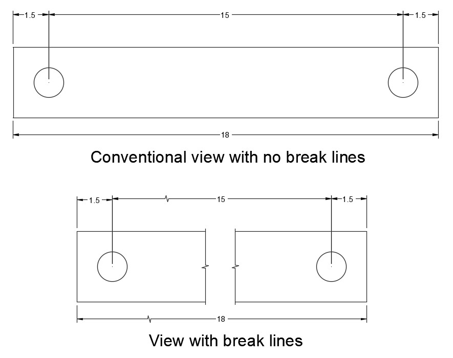
Break lines are used in base views and projected views to save space on prints. On large fabrication projects involving many individual assemblies, each with their own print, paper space and printer ink quickly become commodities. So if part of an assembly doesn’t have many features that need to be dimensioned, part of it will be omitted from the print to save space. This is accomplished with break lines.
Depending on the length of the assembly section that is omitted, either short or long break lines are used. Dimensions are shown across the break in the same manner as they would in a view with no break, as shown in Figure 16.9.
Attributions
- Figure 16.3: 6 principal views by Snebtor is released under CC BY-NC 2.0
- Figure 16.4: Typical Arrangement of Projected Views by Cameron Kjeldgaard, for WA Open ProfTech, © SBCTC, CC BY 4.0
- Figure 16.5: Explanation on Orthographic Projection by Cameron Kjeldgaard, for WA Open ProfTech, © SBCTC, CC BY 4.0
- Figure 16.6: Cutting Plane Line and Section View by Nicholas Malara, for WA Open ProfTech, © SBCTC, CC BY 4.0
- Figure 16.7: Cutting Plane Line and Section View by Nicholas Malara, for WA Open ProfTech, © SBCTC, CC BY 4.0
- Figure 16.8: Detail Views by Cameron Kjeldgaard, for WA Open ProfTech, © SBCTC, CC BY 4.0
- Figure 16.9: Views With and Without Breaks by Cameron Kjeldgaard, for WA Open ProfTech, © SBCTC, CC BY 4.0
A way of representing a three dimensional object using two dimensional drawings.
