16.5 Written Information and Directions
Cameron Kjeldgaard
Title Block
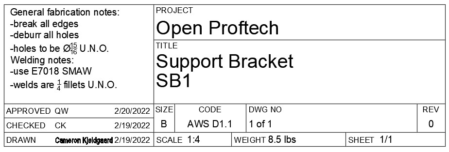
The title block is a ruled space, typically in the lower right corner of the print, that provides general information about the drawing. Although they all have the same general appearance, they may present different information, or the same information but in different locations. It is important to review the title block when beginning any fabrication project, as it provides valuable information, including:
- The project name, which may also be labeled as a job name or job number, is important to know when working in environments where several welding jobs are going on at once.
- The drawing title can be used in place of a numeric or alphanumerical identification. Be sure to check the drawing title or identification to ensure you are working on the correct project.
- A drawing number or sheet number is necessary when working with multi-page drawings.
- A revision number, or revision record, is sometimes abbreviated REV (in Figure 16.25 it appears in the bottom right corner). In large or long-term welding projects, changes can occur while the job is in progress. The revision record keeps track of changes made to the drawing as a result. A revision labeled 0 is the first issue of the drawing. If revisions have been issued, be sure to use the most current revision.
- The scale of the drawing, if there is one, is provided in the title block. If no scale is shown, or if you see the abbreviation NTS, the drawing is not to scale. But if a drawing is to scale then the size and proportions of the object as it is drawn relates to the object’s actual size. This relationship is written as a ratio: The quantity of measure on the drawing is always on the left side of the ratio and the actual measurement on the right. For instance, in the title block in Figure 16.25, the drawing is drawn in a 1:4 scale. This means every one unit of measure on the drawing equals four units of measure on the real life object. Like the scale on a map this is what’s called a reduced scale, meaning the drawing is smaller than, but has a proportional relationship to, the actual object. In full-scale drawings the object is shown on the print in the same size as the actual object. Drawings can also be presented in an enlarged scale for small, detailed parts. An enlarged scale ratio would be written like 4:1, if we reverse our previous example.
- The quantity of assemblies or weldments to be produced may also be shown in the title block (alternatively, this information may be shown in the bill of material, which is discussed in the next section).
- General notes may be included, such as to communicate general fabrication and welding requirements. Be sure to review these requirements prior to fabrication. A few fabrication and welding requirements appear in the upper left corner in Figure 16.25.
Bill of Material
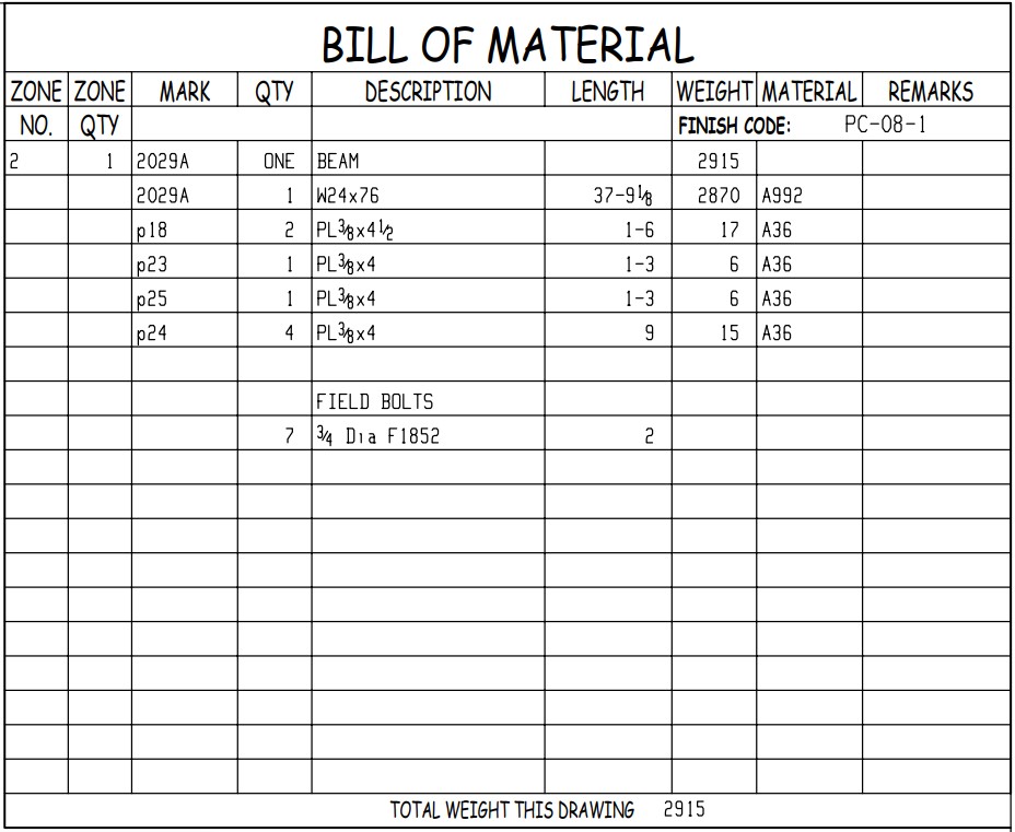
A bill of material, sometimes called a parts list, is usually located in the upper right corner of the drawing. Like the title block, the bill of material is not standardized, and ones used in the construction, aerospace, or pipeline industries may provide different information or present it in a different way. Across industries, the following information commonly appears in the bill of material:
- A quantity of required assemblies and whether multiple assemblies are required. The quantity of parts listed is typically what is needed to complete all assemblies.
- Part numbers, also called mark numbers, are numeric or alphanumeric identifications for individual parts. Part numbers are typically called out with leader lines on the base view of the drawing.
- Part descriptions are usually present and include the dimensions of the part and a letter or symbol to indicate the shape. For plate and sheet parts the convention for listing its size is thickness by width by length. Metal products are produced in many shapes, various styles of I-beam, angle, pipe, square tubing, and so on. Each of these shapes is produced in many sizes and has common conventions for listing their dimensions. The American Institute of Steel Construction has a library of shapes available called The Structural Steel Dimensioning Tool.
- Remarks or notes may also be provided. This is used to provide any type of specific information about the part, such as if it is bent or shaped in some way or requires a special paint or coating.
Notes and Specifications
Any written information on a drawing may be considered a note or specification. It’s easy to become overwhelmed by the complex drawing and number of dimensions on some prints and wanting to gloss over the written notes, but it is important to review all notes and specifications before beginning any fabrication project—missing them can result in a huge amount of rework. Notes may be general or local.
Local notes are given on leader lines and apply to specific parts or features of the project. The hole dimensions discussed in Section 16.4 are examples of local notes. Welding symbols, which are discussed in detail later in this chapter, would also be a local note.
General notes apply to the entire assembly detailed on the print. They usually appear in a ruled out area in the title block but might be placed in any free paper space on the drawing. It’s important to know that general notes on a print are subject to exception. If any part of a print is subject to exception from a general note, a local note on a leader line should be present—if it is not, the general note applies. Also, it is common to see the abbreviation UNO (unless noted otherwise) or UN (unless noted) in general notes. For instance, one may read “All holes to be ¾” diameter UNO,” which is interpreted as meaning “All holes on this assembly are to be three quarters of an inch in diameter, unless noted otherwise.”
Notes may sometimes refer you to other documents. These documents may be quality assurance or fabrication requirements developed by your employer or your employer’s customer. A note may also refer you to a recognized standard, such as a welding or building code. For example, a local note may have a leader line with a note reading “See spec. A.” Then you should consult specification A to ensure that fabrication requirements are met.
