16.7 Dimensions in Weld Symbols
Cameron Kjeldgaard
Fillet Welds
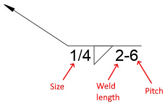
Fillet welds involve fewer dimensions in the welding symbol than groove welds. In the simplest case, just the fillet weld symbol and its size will be present. For both fillet and groove welds, the weld size is always declared on the left of the weld symbol. If the weld size is the only dimension present that indicates it is a continuous weld and should go the entire length of the weld joint.
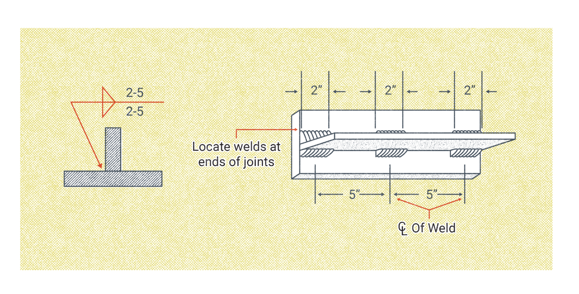
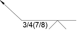
The two dimensions that may appear to the right of the weld symbol are its length and pitch. These define how to complete an intermittent weld, sometimes called a stitch weld. It is often unnecessary to weld the entire length of long weld joints so, for instance, a print may call for a two-inch-long weld (the length) spaced every six inches (the pitch). The spacing is measured from the center of one weld to the center of the next weld. You can see this illustrated in Figure 16.35, where the weld symbol calls for two-inch-long welds on a five-inch pitch.
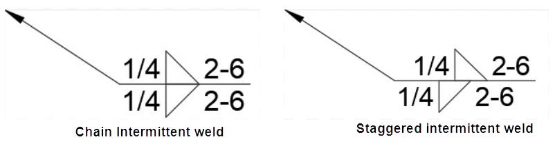
Intermittent welds may also be chained or staggered. In chained welds, the welds on each side of the joint are lined up with each other. If the welds are staggered, however, then the welds on one side of the joint are offset from the welds on the other. It is best to offset the welds by half the required pitch, so that welds on one side of the joint are centered between the welds on the other side. A slight offset of the weld symbols indicates the welds should be staggered (see Figure 16.36).
When reading weld symbols, know that a pitch will never be given without a length as well, but that a length may be given without a pitch. This means if there is only one number to the right of the welding symbol rather than two, it is for the length of the weld.
If only a length is given in the print, the detailer may use dimension and extension lines to indicate where the weld should be located on the joint. If this is not done, it is best practice for welders to center the weld on the joint.
Groove Welds
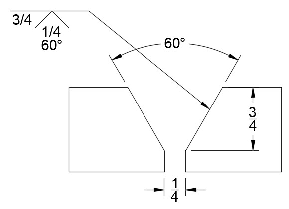
Groove welding symbols can be more involved and complex than fillet welding symbols. Just like with the fillet weld, the size always appears on the left of the weld symbol. Groove weld size is a reference to the depth of the groove cut into the material. If no size is shown, then assume the groove depth is the same as the material thickness, such that the groove is cut all the way through the material with no root face. If there is a root opening it is shown directly below the weld symbol, with the groove angle directly below that. If the weld symbol is on top of the reference line, the root opening and groove angle with be shown in an ascending order.
It is not always the case, but groove welding symbols may have two sizes shown to the left of the weld symbol: one with no parentheses and a second contained within parentheses. The size not in parentheses references the depth of the groove prior to welding—the same as if no second size was present. But the size shown in parentheses is the required size of the finished weld. The weld size is typically larger than the groove depth, and it indicates a required amount of penetration into the joint root.
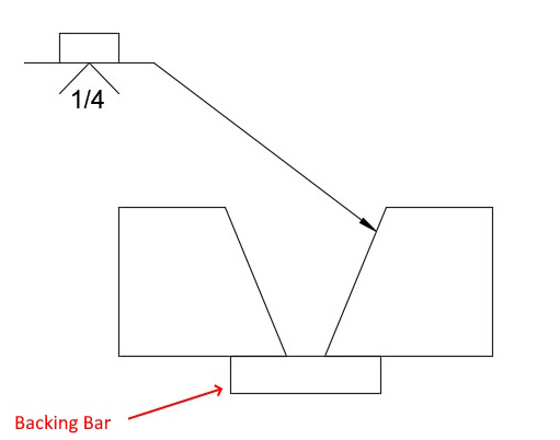
Groove welds with root openings often use backing bars. Root openings allow for complete penetration of the weld joint, and the backing bar prevents the molten weld metal from falling out of the root side of the joint. The backing bar symbol is a small rectangle, and it is placed on the opposite side of the reference line from the groove symbol. In some cases the letter R may be present within the backing bar symbol, which indicates the backing bar should be removed once welding is complete.
Plug and Slot Welds
The plug weld symbol is a simple rectangle and, therefore, it can be confused with the backing bar symbol. However, if there is no groove symbol on the other side of the reference line, it is safe to assume a plug weld is called for.
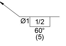
The diameter of the hole the plug weld is going in is shown to the left of the plug weld symbol, making use of the diameter symbol. A number inside the rectangle itself indicates the depth to which the plug should be filled with weld metal. If the hole is to be countersunk, the degree of the countersink will appear directly below or directly above the weld symbol. It is very common for multiple plug welds to be used when joining two parts, so the number of required welds appears in parentheses directly below or directly above the listed angle of countersink. When multiple plug welds are needed their locations will be detailed on the print.
Slot welding symbols use the same rectangular weld symbol as for plug welds; however, in the case of slot welds the diameter symbol will not be present to the left of the symbol, just a number indicating the width of the slot. The length of the slot will appear to the right of the symbol.
Attributions
- Figure 16.34: Intermittent Fillet Weld Symbol by Cameron Kjeldgaard, for WA Open ProfTech, © SBCTC, CC BY 4.0
- Figure 16.35: The Significance Of The “Length And Pitch” Elements Of The Weld Symbol Used In Intermittent Fillet Welding. by Nicholas Malara, for WA Open ProfTech, © SBCTC, CC BY 4.0
- Figure 16.36: Chain and Staggered Fillet Weld Symbols by Cameron Kjeldgaard, for WA Open ProfTech, © SBCTC, CC BY 4.0
- Figure 16.37: V Groove Weld Symbol by Cameron Kjeldgaard, for WA Open ProfTech, © SBCTC, CC BY 4.0
- Figure 16.38: Groove Weld Sizes by Cameron Kjeldgaard, for WA Open ProfTech, © SBCTC, CC BY 4.0
- Figure 16.39: V Groove with Backing Bar by Cameron Kjeldgaard, for WA Open ProfTech, © SBCTC, CC BY 4.0
- Figure 16.40: Plug Weld Symbol by Cameron Kjeldgaard, for WA Open ProfTech, © SBCTC, CC BY 4.0
A weld that goes the entire length of the weld joint.
Sometimes called stitch welds, intermittent welds are used when it is unnecessary to weld the entire length of long weld joints. Instead, welds are performed in small increments, usually uniformly in size and spacing.
