17.3 American Welding Society (AWS) Welding Codes
David Colameco, M.Ed.
Development of AWS Welding Codes
During World War I, industry used welding to fabricate materials for the war effort. In 1919, the AWS was founded “as a nonprofit organization with a global mission: to advance the science, technology, and application of welding and allied joining and cutting processes worldwide, including brazing, soldering, and thermal spraying” (American Welding Society, n.d.) This mission statement by AWS shows the broad knowledge and subject areas that the organization covers, but for the purposes of this discussion, we will focus on welding.
AWS has many committees comprising experts and contributors working together to meet the organization’s mission. These committees come to decisions based on a consensus approach where voting members cast a ballot. It is a formal process where objections of voting members are discussed, and the public can provide input. Everyone, including you, has the opportunity to address these committees when they meet. To achieve the purpose of AWS, about 200 committees were formed to address various topics. The covers of the documents on these topics are color coded as such:
- Fundamentals: brown
- Qualification and Inspection: green
- Processes: blue
- Industrial Applications: red
- Safety and Health: yellow
- Materials: tan
- Welding Equipment: purple
AWS maintains about 300 standards in the subject areas listed above. As you read over this small list of AWS standards, think of all of the possibilities your career can take in structural welding alone! The next few sections provide an overview of the following structural codes:
- AWS D1.1/D1.1M:2020 Structural Welding Code – Steel
- AWS D1.2/D1.2M:2014 Structural Welding Code – Aluminum
- AWS D1.3/D1.3M:2018 Structural Welding Code – Sheet Steel
- AWS D1.4/D1.4M:2018 Structural Welding Code – Steel Reinforcing Bars
- AWS D1.5/D1.5M:2020 Bridge Welding Code
- AWS D1.6/D1.6M:2017 Structural Welding Code – Stainless Steel
- AWS D1.7/D1.7M:2010 Structural Welding – Guide for Strengthening and Repairing Existing Structures
- AWS D1.8/D1.8M:2021 Structural Welding Code – Seismic Supplement
- AWS D1.9/D1.9M:2015 Structural Welding Code – Titanium
The codes listed above have a forward slash (/) with a repeat of the number and an M for “metric.” This enables one single standard to address both U.S. and metric units rather than having two separate documents for each measurement system. In addition, there is a publication year given just after the colon (:), which, as of the writing of this chapter, were the latest code versions. If your school, employer, union hall, library, or other organization provides copies of welding standards to read, it is important to request new standards when they come out to show your interest in an up-to-date collection. AWS standards are typically on a five-year publication cycle; however, you may have noticed in the list above that this does not always happen. For example, the D1.7 code hasn’t been revised for over 10 years.
Basics of the AWS Welding Codes
The AWS has recently put in a significant effort to streamline its standards to make them look similar in structure. So, generally speaking, the codes listed in the section above have the same chapters, which are called clauses in AWS standards. These are the clauses from D1.1/D1.1M:2020:
- Clause 1: General Requirements
- Clause 2: Normative References
- Clause 3: Terms and Definitions
- Clause 4: Design of Welded Connections
- Clause 5: Prequalification of WPSs
- Clause 6: Qualification
- Clause 7: Fabrication
- Clause 8: Inspection
- Clause 9: Stud Welding
- Clause 10: Tubular Structures
- Clause 11: Strengthening and Repair of Existing Structures
Clause 6 is the part of the standard that will detail the setup of the certification test, inspection criteria, and destructive testing required, which is important for welders who are working towards certification.
The other standards listed in this chapter have similar structures for Clauses 1–8. D1.6 has the same Clauses 1–9, while D1.2 and D1.9 have an older structure that is similar but will likely be updated to the streamlined structure in future releases. However, D1.5 has Clause 5: Workmanship and Clause 6: Technique, but together they are similar to the fabrication clauses in other codes.
During your welding career, if your work takes you in the direction of applying a different welding code than you were previously using, it is recommended that you, at minimum, read over the sections pertaining to qualification, fabrication, and inspection to better understand the new requirements you are welding to.
Uses of the AWS Welding Codes In Industry Today
AWS codes are used worldwide but with varying acceptance depending on the country. In the U.S., the AWS codes are used in all 50 states and inhabited territories.
As mentioned previously, most structural steel in Washington state is done under WABO. However, some industries in Washington state may also follow AWS standards for steel construction. But WABO does not cover other materials aside from steel; therefore, most structural welding of other metals, such as aluminum or stainless steel, would require an AWS code. AWS D1.5 Bridge Welding Code is used for fabrication of bridges.
Getting Certified to the AWS Welding Codes
Some community colleges and technical schools offer AWS certification testing. As you explore your career options in welding, check out which codes and certifications the employers in those areas use and require.
For the purposes of this chapter, we will focus on the AWS D1.1 certification tests because structural steel is one of the most common welding career paths. However, each out to the testing facility to get up-to-date information prior to practicing for a certification test, as changes from what is written here may have occurred.
Getting certified to AWS D1.1 or WABO will be beneficial to your career because then employers can know that you are highly likely to successfully qualify under another code if you are given time to practice. Welders and welding operators are tested by welding on plates or tubular structures, depending on the qualification.
A list of qualification types is classified as follows in D1.1 Clause 6:
- Complete joint penetration (CJP) groove welds for nontubular connections
- Partial joint penetration (PJP) groove welds for nontubular connections
- Fillet welds for nontubular connections
- CJP groove welds for tubular connections
- PJP groove welds for tubular connections
- Fillet welds for tubular connections
CJP means that the weld penetrates the base material from one side to the other; in other words, the weld bead(s) have been laid down from one side of the base material and built up until they reach the other side of the base material. PJP means that the weld only goes part of the way through the base material depth in the joint.
Let’s examine each one of these qualification type classifications in more detail.
CJP and PJP Groove Welds for Nontubular Connections
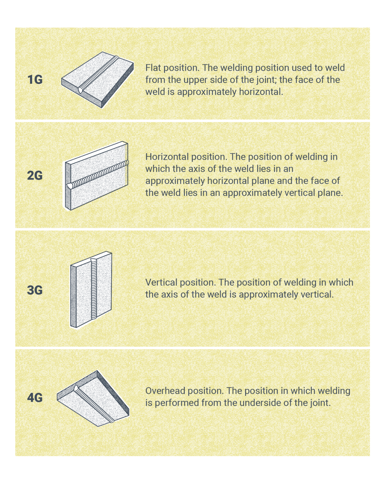
Tubular connections are welds that involve shapes such as pipes and tubes. Nontubular connections are typically flat shapes such as plates. Figure 17.3 shows the four welding positions for plates with groove welds.
Welders and welding operators qualifying for CJP are qualified for PJP welding.
AWS D1.1/D1.1M:2020 Clause 6, Table 6.1 lists the following weld types and positions for qualification tests on plates:
- CJP 1G: CJP and PJP for production plate in the flat position
- CJP 2G: CJP and PJP for production plate in the flat and horizontal positions
- CJP 3G: CJP and PJP for production plate in the vertical position
- CJP 4G: CJP and PJP for production plate in the overhead position
The thickness of the plates used in qualification tests determines the thickness of plates a welder is qualified to weld in production, as seen in Table 17.1.
| Plate Thickness | Qualification |
|---|---|
| ⅜” | Qualifies the welder for ⅛” to ¾” |
| ⅜” to 1” | Qualifies the welder for ⅛” to twice the thickness of the test plate |
| 1” and over | Qualifies the welder for ⅛” to unlimited thickness |
(AWS, D1.1/D1.1M:2020, Table 6.11)
Testing has visual acceptance criteria for evaluating welder and welding operator performance. Welders interested in qualifying for production plate welding should contact the testing facility or consult the latest version of D1.1 for the specific acceptance criteria. The acceptance criteria are broken down into the following areas in Table 8.1 of AWS D1.1/D1.1M:2020:
- Crack prohibition
- Weld/base metal fusion
- Crater cross section
- Weld profiles
- Time of inspection
- Undersized welds
- Undercut
- Porosity
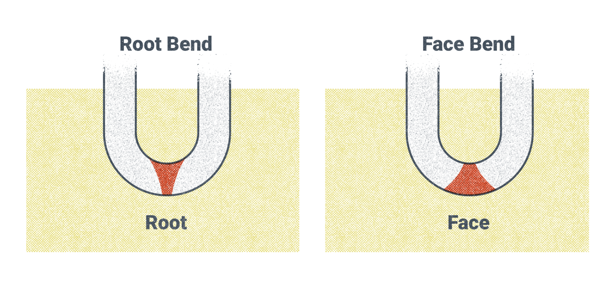
Following a visual inspection, your weld would undergo a bend test in accordance with AWS D1.1 or the standard you are qualifying for. There are face bends, root bends, and side bends.
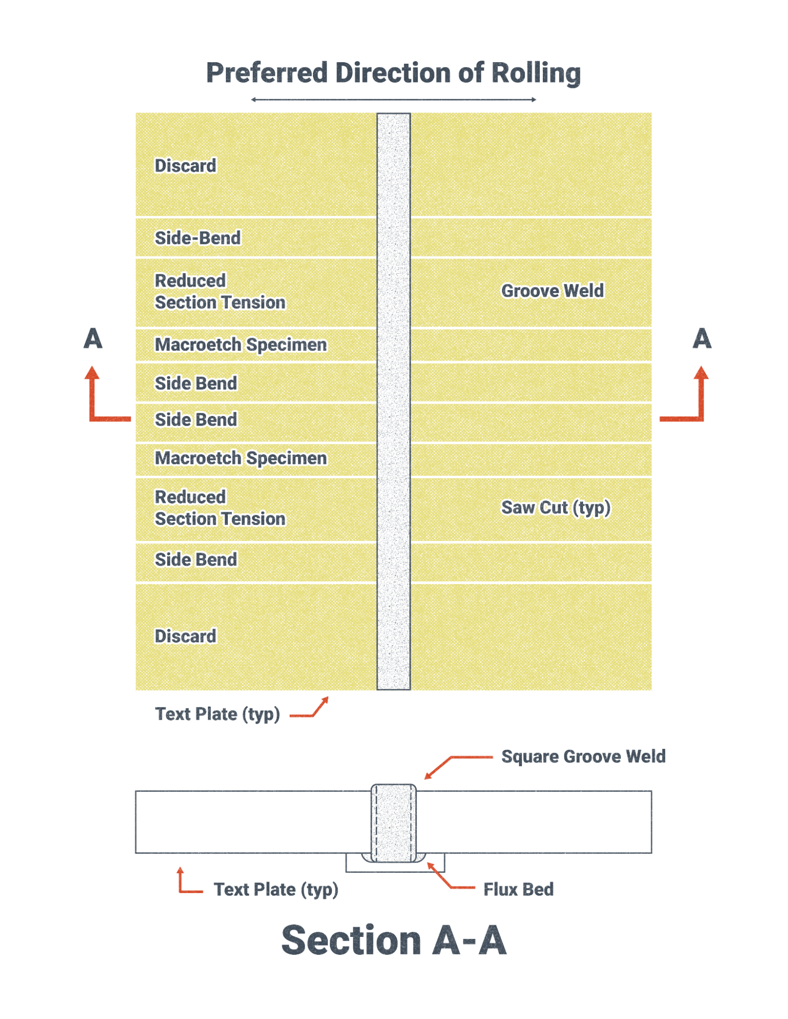
Figure 17.4 shows a test plate and the locations where face bends are cut out for testing. In D1.1, there is a space between the bend specimens.
Once the specimens are cut out of the welder’s test plates, they are bent in a bend test machine such as the one shown in Figure 17.5. Some test machines are manually operated, while others are powered electrically or pneumatically (through air pressure).
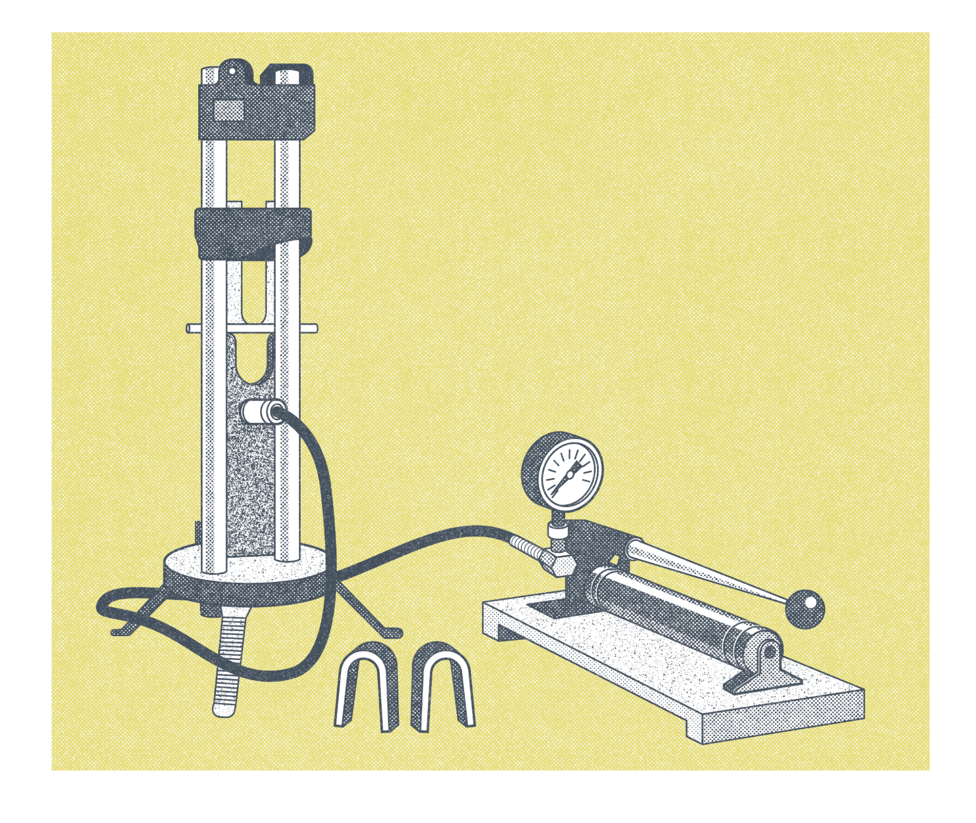
The reasoning behind using a manual or machine bend testing machine typically depends on the budget and number of bend tests performed in a given period of time. A manual bend tester would be more ideal for performing a few bend tests done infrequently. For example, if you were testing your own welds at home about once or twice a year, then a hand-operated system would make sense. If you were a company or school that was performing dozens of bend tests a month then a machine, like the one in Figure 17.6, makes more sense from a productivity standpoint.
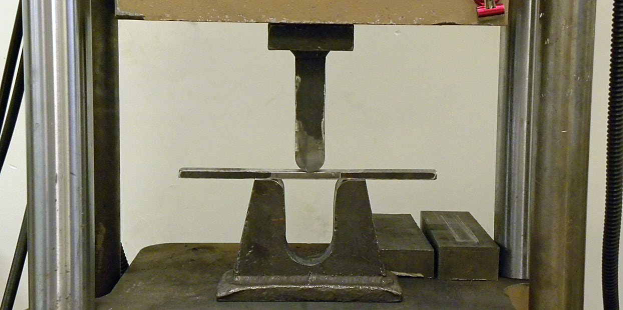
To perform the test, the material specimen is placed into the machine between the plunger and the U-shaped die. Both root and face bends can be achieved; it just depends on which side is facing away from the plunger. To get a root bend, the root faces away from the plunger and is visible on the outside of the bend; this causes the root portion of the weld to stretch. To get a face bend, the weld face faces away from the plunger and is visible on the outside of the bend; this causes the face portion of the weld to stretch.
A perfect bend test would show a continuous surface free of any changes such as tears and holes from porosity or slag inclusions, also known generally as discontinuities. The inspector checks the surface of the bend for any discontinuities, such as tears and holes, and compares the size, shape, and quantity to the code’s visual acceptance criteria. The bend test is passed if a discontinuity is smaller than the acceptance criteria. But if the discontinuity is larger than the acceptance criteria, then the discontinuity is too large and it is a defect—the bend test is failed.
Fillet Welds for Non-tubular Connections
Fillet welds made on plates are non-tubular connections. Figure 17.8 shows four test positions for fillet welds on T-joints.
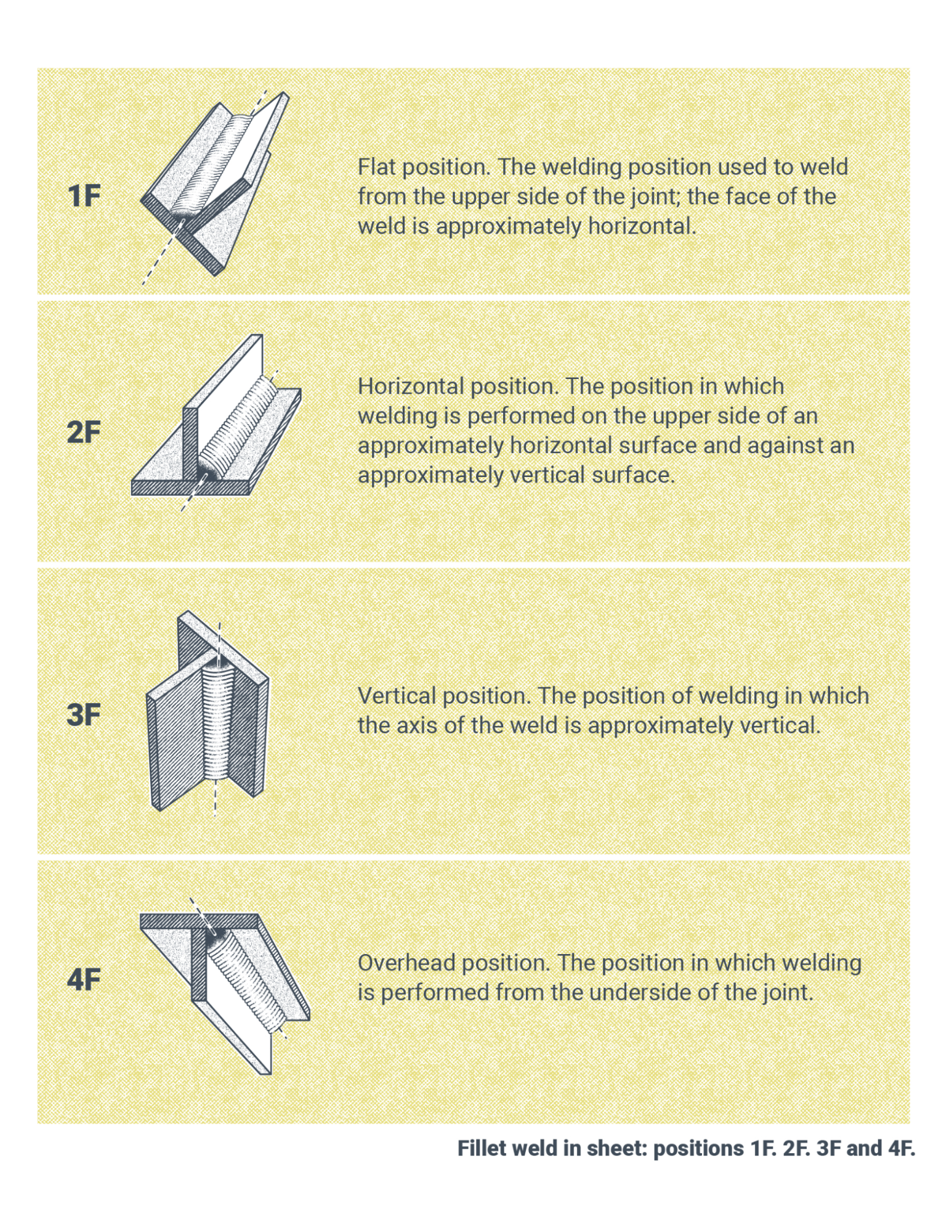
Welders and welding operators qualifying for CJP are qualified for PJP welding. AWS D1.1/D1.1M:2020 Clause 6, Table 6.1 lists the following weld types and positions for qualification tests on plates:
| Weld Position | Qualification |
|---|---|
| CJP 1F | CJP and PJP for Production Plate in the Flat position |
| CJP 2F | CJP and PJP for Production Plate in the Flat and Horizontal positions |
| CJP 3F | CJP and PJP for Production Plate in the Vertical position |
| CJP 4F | CJP and PJP for Production Plate in the Overhead position |
Note: From AWS D1.1/D1.1M:2020 (Clause 6, Table 6.1). Copyright 2020 by the American Welding Society.
The thickness of the plates used in qualification tests determines the thickness of plates a welder is qualified to weld in production. AWS D1.1/D1.1M:2020 Table 6.11 lists Fillet Option 1 thickness as 0.5 inch, which qualifies the welder for 0.125 inch to unlimited thickness.
This qualification test requires passage of both a macroetch test and a fillet weld break test.
The fillet weld break test, shown in Figure 17.9, involves applying a force to the fillet weld. If the fillet does not fail under the required force, then the test passes.
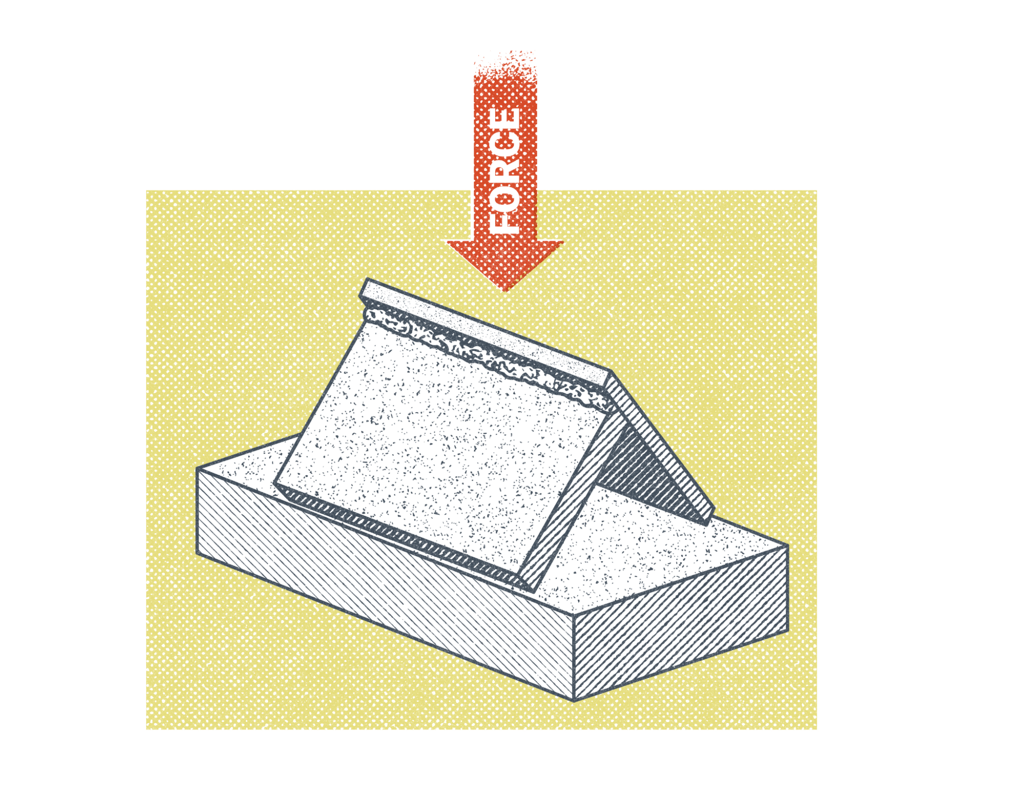
The macroetch test involves cutting the T-joint perpendicular to the weld bead (considering Figure 17.9, imagine that the arrow labeled “force” was a cutting blade that cut the T-joint in half to expose the internal of the fillet weld). Once the cut is made, the surface is prepped and an acid is applied to etch the metal. This reveals the grain structure of the weld and heat-affected zone, making it easier to inspect. Figure 17.10 shows a macroetch of a T-joint.
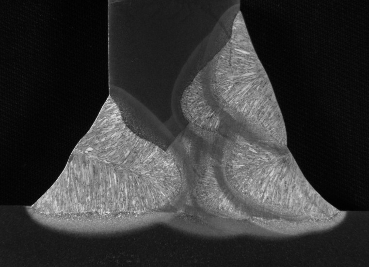
This test requires that the largest single bead fillet weld be made on one side of the T-joint and the minimum multi-pass beads be made on the other side. The acceptance criteria are as follows:
- Fillet welds shall have fusion to the root of the joint but not necessarily beyond.
- Minimum leg size shall meet the specified weld size.
The legs of the weld are the size of the weld along the base material prior to welding. The legs are denoted by the “Proper Size” labels in Figure 17.11.
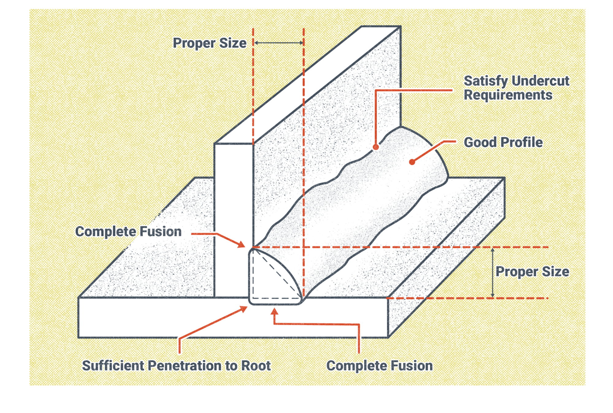
If the weld passes the acceptance criteria, the macroetch test passes.
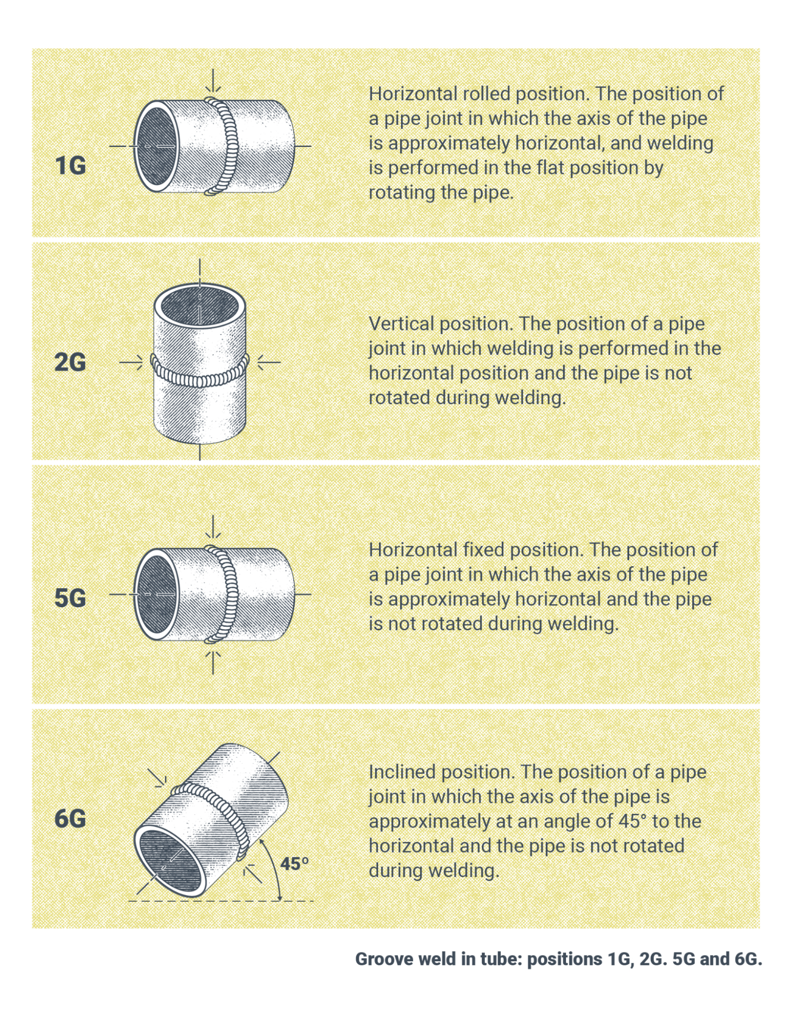
CJP and PJP Groove Welds for Tubular Connections
Welders and welding operators qualifying for CJP are qualified for PJP welding. AWS D1.1/D1.1M:2020 Clause 10, Table 10.12 lists the following weld types and positions for qualification tests on plates:
| Plate Position | Qualification |
|---|---|
| 1G Rotated | CJP and PJP for Production Pipe in the Flat position |
| 2G | CJP and PJP for Production Pipe in the Flat and Horizontal positions |
| 5G | CJP and PJP for Production Pipe in the Flat, Horizontal, Vert. position |
| 6G | CJP and PJP for Production Plate in All Positions |
| (2G + 5G) | CJP and PJP for Production Plate in All Positions |
Note: From Structural Welding Code – Steel. AWS D1.1/D1.1M (Clause 10, Table 10.12), 2020. Copyright 2020 American Welding Society.
The size and thickness of the pipes used in qualification tests determines the size and thickness of plates a welder is qualified to weld in production. AWS D1.1/D1.1M:2020 (Table 10.13) lists three size and thickness combinations, shown here in Table 17.4.
| Pipe Size* | Qualification |
|---|---|
| ≤ 4” Pipe, Unlimited Thick | Qualifies ¾” to 4” Pipe for ⅛” to ¾” Thickness |
| > 4” Pipe, ≤ ⅜” Thickness | Qualifies 4”* to Unlimited Pipe for ⅛” to ¾” Thickness |
| > 4” Pipe, < ⅜” Thickness | Qualifies 4”* to Unlimited Pipe for 3/16” to unlimit Thickness |
Note. The minimum pipe size qualified shall be half the test diameter or 4”, whichever is greater. AWS D1.1/D1.1M:2020 (Table 10.13). Copyright 2020 American Welding Society.
It is important to note that this material is rather extensive, and welders wishing to qualify on tubular connections should speak with their training facility, testing facility, and consult AWS D1.1/D1.1M:2020 Table 10.13 or the latest version of D1.1 for the most up-to-date information about the certification test and its requirements.
Groove welds made on tubular connections are shown in Figure 17.12 for various positions.
Fillet Welds for Tubular Connections
Fillet welds made on tubular connections are shown in Figure 17.13.
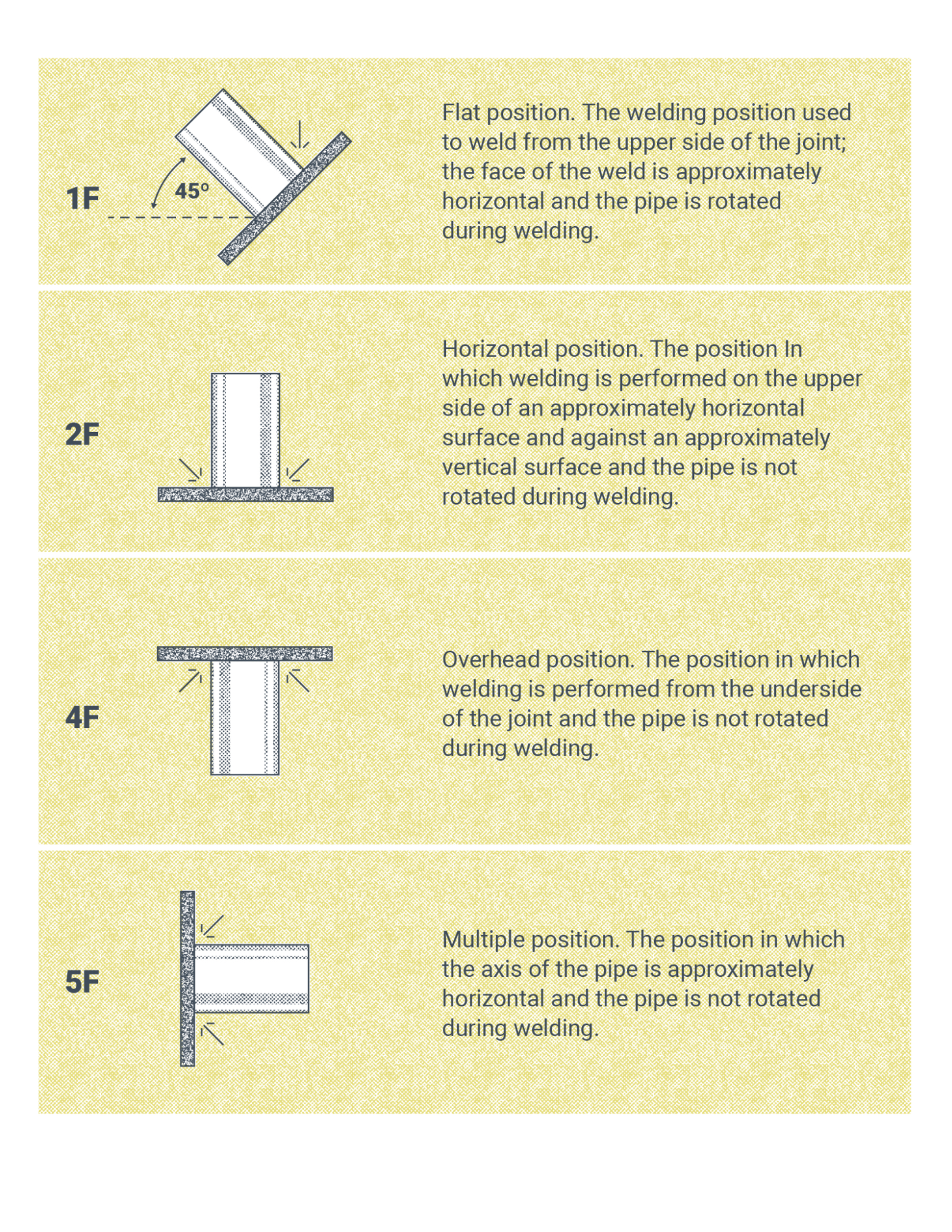
Welders and welding operators qualifying for CJP are qualified for PJP welding. AWS D1.1/D1.1M:2020 Clause 10 (Table 10.12) lists the weld types and positions for qualification tests on plates, shown here in Table 17.5.
| Weld Test Position | Description |
|---|---|
| 1F | Fillets for production pipe in the flat position |
| 2F | Fillets for production pipe in the flat and horizontal positions |
| 2F Rotated | Fillets for production pipe in the flat and horizontal positions |
| 4F | Fillets for production plate in the flat, horizontal, overhead positions |
| 5F | Fillets for production plate in all positions |
The thickness of the plates used in qualification tests determines the thickness of plates a welder is qualified to weld in production. AWS D1.1/D1.1M:2020 (Table 6.11) lists three plate thicknesses:
- Unlimited Size, ≥ ⅛”
- Qualifies the welder for diameter pipe tested to unlimited
- ⅛” to unlimited wall thickness
- 30 to unlimited dihedral angle
A dihedral angle is the angle measured in a plane perpendicular to the line of the weld—perpendicular to the tangents of the pipe surfaces being welded together. For a visual, see the first figure in Annex Q of AWS D1.1/D1.1M:2020. As you look at this figure, note that the toughest part to weld is where the local dihedral angle is the smallest while the easiest part of the weld to access is where the local dihedral angle is the largest.
Plug and Slot Welds for Tubular and Nontubular Connections
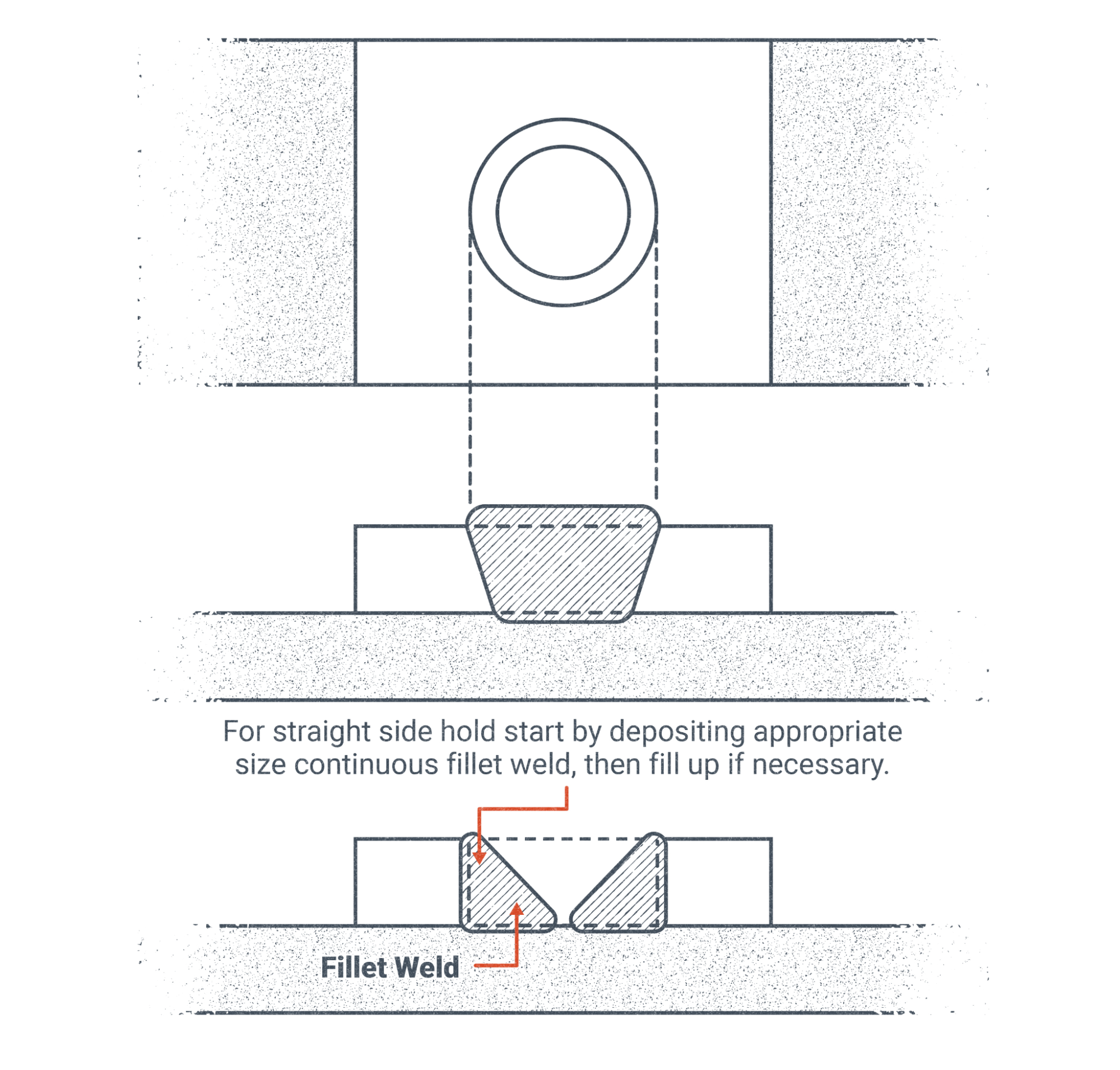
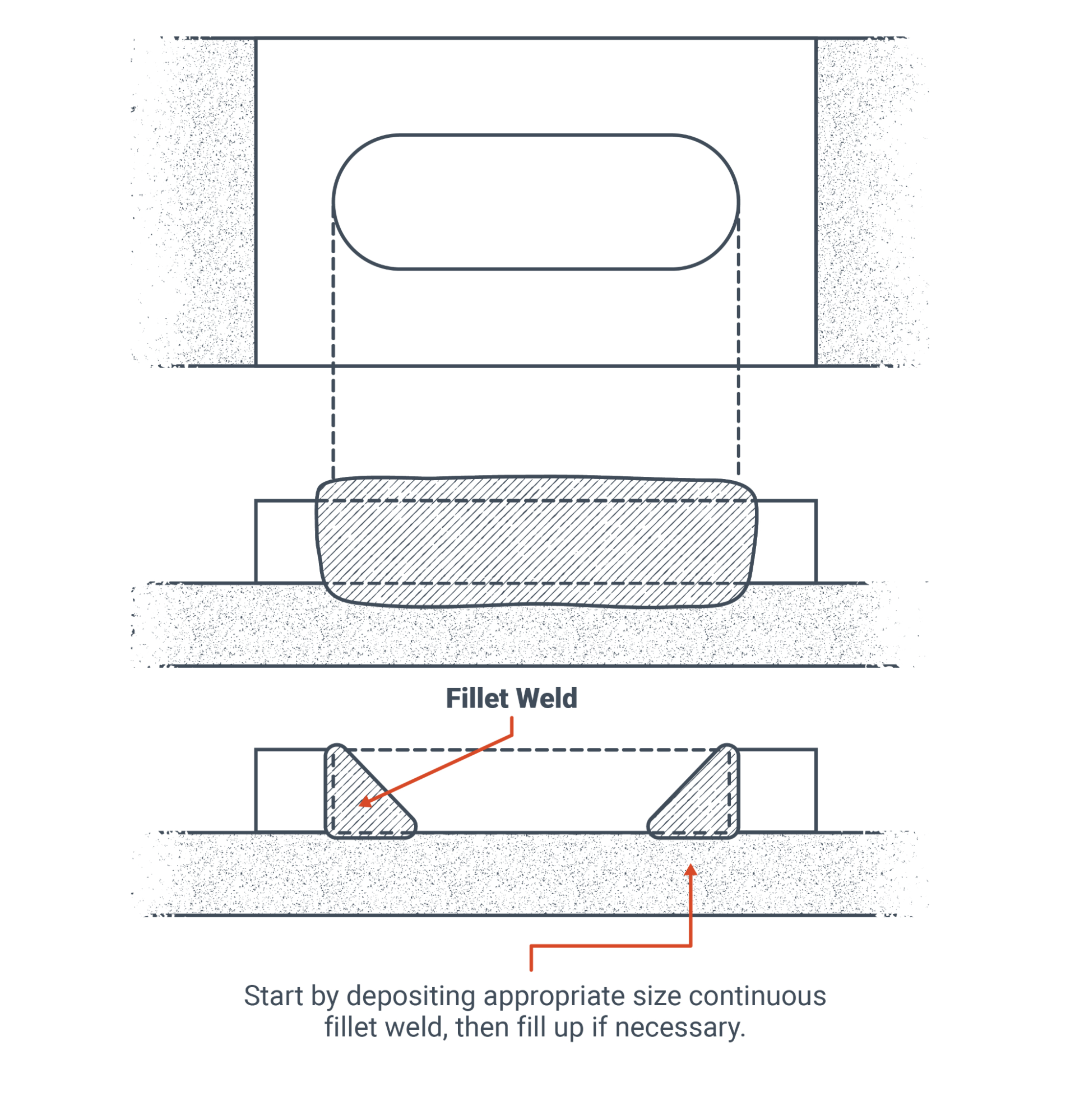
Plug and slot welds are used to join two metal surfaces together where there normally isn’t a joint or seam to weld them together. Imagine two very large plates that are more than 10 feet by 10 feet that you want to weld together. If you only welded them at the edges, the two plates might come apart at the center if they are oriented parallel to the ground because they would sag under their own weight. To prevent this sagging you could cut holes or slots in the area away from the edge and weld the two plates in more locations to join them across the entire faying surface (where two pieces of metal come in contact with each other).
Figure 17.14 and Figure 17.15 show plug and slot welds respectively. These figures provide the instructions to first weld a fillet weld around the inside of the plug or slot cutout and then fill as necessary.
Welders and welding operators qualifying for plug and slot welding will refer to AWS D1.1/D1.1M:2020 Clause 6. There the following statement about qualifications is made: “Plug: Qualifies Plug and Slot Welding only for the Positions Tested” (American Welding Society, 2020b).
For thicknesses tested and thicknesses qualified, D1.1/D1.1M:2020 (Table 6.11) lists that for a plate thickness of 0.375 inch, it qualifies for 0.125 inch to unlimited thickness.
Attributions
- Figure 17.2: Tacoma Narrows Bridges by Washington State Dept of Transportation is released under CC BY-NC-ND 2.0
- Figure 17.3: Groove Welding Positions by Nicholas Malara, for WA Open ProfTech, © SBCTC, CC BY 4.0
- Figure 17.4: Test Specimen Directions by Nicholas Malara, for WA Open ProfTech, © SBCTC, CC BY 4.0
- Figure 17.5: Bend Test Machine by Nicholas Malara, for WA Open ProfTech, © SBCTC, CC BY 4.0
- Figure 17.6: Test setup by U.S. Department of Transportation, Federal Highway Administration in the Public Domain; United States government work
- Figure 17.7: Root and Face Bends by Nicholas Malara, for WA Open ProfTech, © SBCTC, CC BY 4.0
- Figure 17.8: Fillet Welding Positions by Nicholas Malara, for WA Open ProfTech, © SBCTC, CC BY 4.0
- Figure 17.9: Fillet Rupture Test by Nicholas Malara, for WA Open ProfTech, © SBCTC, CC BY 4.0
- Figure 17.10: Photo. Example macroetch of a T-joint mockup. by U.S. Department of Transportation, Federal Highway Administration in the Public Domain; United States government work
- Figure 17.11: Parts of a T-Joint by Nicholas Malara, for WA Open ProfTech, © SBCTC, CC BY 4.0
- Figure 17.12: Groove Welding Positions in Tubes by Nicholas Malara, for WA Open ProfTech, © SBCTC, CC BY 4.0
- Figure 17.13: Fillet Welding Positions by Nicholas Malara, for WA Open ProfTech, © SBCTC, CC BY 4.0
- Figure 17.14: Plug Joint In Flat Position by Nicholas Malara, for WA Open ProfTech, © SBCTC, CC BY 4.0
- Figure 17.15: Slot Joint In Flat Position by Nicholas Malara, for WA Open ProfTech, © SBCTC, CC BY 4.0
When the weld penetrates the base material from one side to the other, in other words the weld bead(s) have been laid down from one side of the base material and built up until they reach the other side of the base material.
Partial joint penetration means that the weld only goes part of the way through the base material depth in the joint.
A destructive test used to determine the quality of a weld during quality testing.
An angle that describes the relationship between two external surfaces on the base material in a weld joint.
