18.2 Parts of the WPS
David Colameco, M.Ed.
This section breaks down the WPS into sections to make it easier to explain its parts. There is no right or wrong way to break up a WPS for explaining it. Your instructor may choose to split the WPS into even smaller pieces or even just explain the whole thing in one long discussion.
Throughout this chapter we will refer to a NASA WPS, called NASA-A36-FCAW-AWS, which is for flux-cored arc welding (FCAW) of carbon steel.
Upper Portion of a WPS
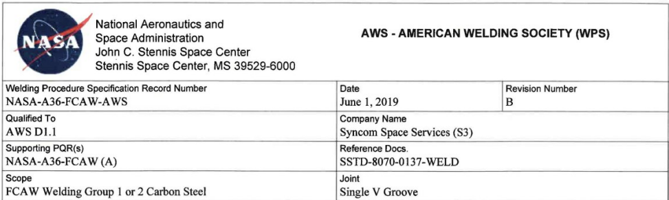
The upper portion of a WPS, shown in Figure 18.1, typically has the company or organization’s name and address to identify who the WPS belongs to. Additional information in the second row at the top has the WPS number, the date, and revision number of the WPS. The third row contains the code that the WPS is qualified to and identifies the subcontractor. The next row lists the supporting PQR that was used to write this WPS as well as the document that serves as the reference for this WPS. and the last row shows the scope of the welding (in the Figurer 18.1 example it is FCAW for group 1 or 2 carbon steel) and joints (a single V-groove joint).
AWS organizes similar materials into groups to make it easier to develop WPSs. When materials weld in a similar manner and are grouped together, you don’t necessarily have to develop a whole new PQR for every metal or alloy you are welding.
Base Materials and Thickness Range Qualified
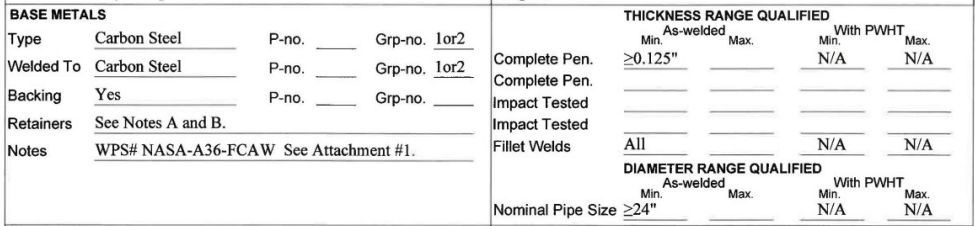
These next parts of a WPS, seen in Figure 18.2, are filled out by a qualified representative who has experience and knowledge of the welding code being used.
The left portion of this section is about the base materials. A36, seen identified on the notes line, is a common carbon steel that is used in welding schools across the country due to its widespread structural use and ease of welding. This WPS allows for A36, which is part of AWS group 1, to be welded to groups 1 and 2. It also allows other materials in group 1 to be welded to group 1 or 2 materials, and also for group 2 materials to be welded to group 1 or 2 materials. As you can see, this WPS allows for many steel alloys to be welded together.
The thickness range qualified material is on the right-hand side of this section. Here the thickness range qualified is for all thicknesses greater than or equal to 0.125 inches. This section also denotes that all fillet welds qualify. The “with PWHT” column stands for post-weld heat treatment. This means that the end product is welded and then no post-processing, such as a PWHT, is used. It can be cleaned and painted or other process that does not alter the mechanical properties of the material. In this case PWHT is not applicable.
This WPS also includes a diameter range qualified, with this one allowing for pipe diameters of greater than or equal to 24 inches. At a certain point a large diameter pipe is similar to welding on flat plates, which is why welding schools usually have you weld on plates first in a pipe class before welding on actual pipes.
Filler Metals
The next portion of the WPS lists the filler metals that can be used with this WPS. In this case a note (Note D) is used to further discuss the filler metal classification. The thickness range qualified is greater than or equal to 0.125 inches thick material in the as-welded condition. A PWHT is not applicable here.
Welding Procedure Portion of a WPS
| Welding Process | FCAW | FCAW |
|---|---|---|
| Type | Semi-Automatic | Semi-Automatic |
| Minimum preheat/interpass temperature (°F) | 320°F (See Note E) | 320°F (See Note E) |
| Maximum interpass temperature (°F) | 500°F | 500°F |
| Tungsten Size | N/A | N/A |
| Tungsten Type | N/A | N/A |
| Filler Metal Size (in.) | 0.045 – 0.052 | 0.045 – 0.052 |
| Layer Number | Root | 2-Cap |
| Position of Groove | (See Note G) | (See Note G) |
| Weld Progression | N/A | N/A |
| Current/Polarity | DCEP (See Note F) | DCEP (See Note F) |
| Amperes | N/A | N/A |
| Volts | 24.5-30 | 24.5-30 |
| Travel Speed (in./min) | 5 – 12 ipm | 8 – 20 ipm |
| Maximum Heat Input (kj/in) | N/A | N/A |
| DC Pulsing Current | N/A | N/A |
| Shielding: Gas Type | Argon/CO2 – 75%/25% | Argon/CO2 – 75%/25% |
| Shielding: Flow Rate (cfh) | 30-60 CFH | 30-60 CFH |
| Trailing: Gas Type | N/A | N/A |
| Trailing: Flow Rate (cfh) | ||
| Backing: Gas Type | N/A | N/A |
| Backing: Flow Rate (cfh) | ||
| String or Weave | String or (Weave ≤= ⅝”) | String or (Weave ≤= ⅝”) |
| Orifice/Gas Cup size | ⅜” – ¾” | ⅜” – ¾” |
| Multi/Single Pass per Side | Multiple (See Note C) | Multiple (See Note C) |
| Weld Deposit Chemistry | ||
| Notes: Contact Tube to Work Distance – ½” to 1”. Single Electrode | ||
Note: From Compliance is Mandatory, John C. Stennis Space Center, Flux Cored Arc Welding of Carbon Steel for ⅛-inch to Unlimited Plate Thickness, National Aeronautics and Space Administration
Table 18.1 shows the welding procedure portion of a WPS, with this one copied from the NASA WPS being referred to throughout this chapter. This section contains the settings you will use to perform the welding. Notice that the left-most column lists the parameters such as preheat, filler metal size, volts, shielding gas, etc. The columns to the right are for the root and then the following passes, including the cap pass.
Have you welded using the FCAW process before? If yes, do the machine settings such as voltage and electrode size look familiar? And if you haven’t welded FCAW before, do these look like machine settings you would need to know?
Page 2 Upper Portion of a WPS
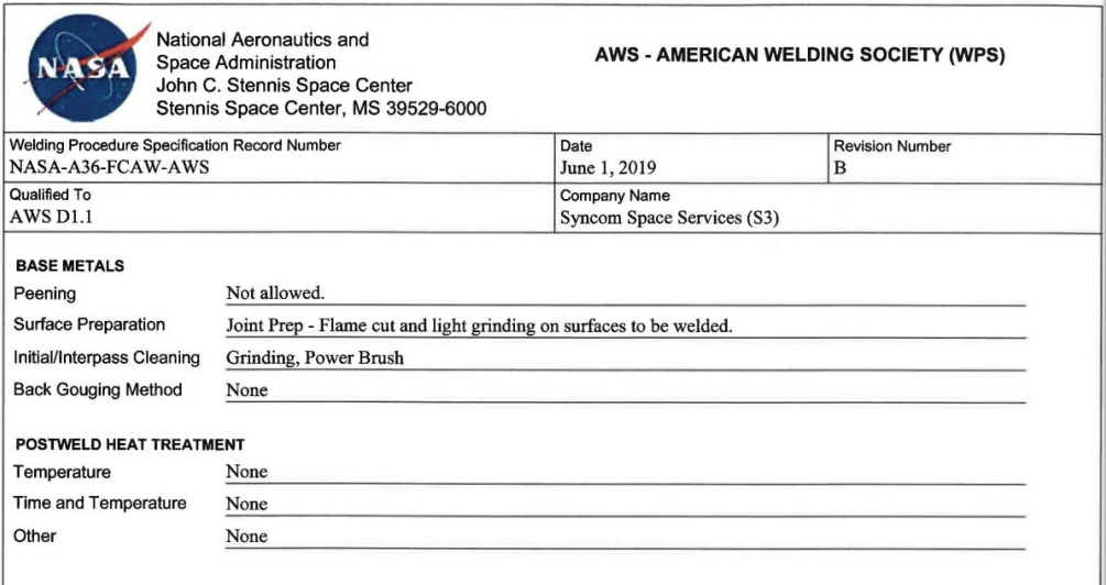
The upper portion of the second page of this WPS is shown in Figure 18.4. This part of the form repeats some information from the top portion of the previous page, including the WPS record number, date of the form, the revision number, the code that the WPS is qualified to, and the subcontractor.
Following the identification information, the base metals requirements are listed. The first piece of information is about peening, specifically that it is not allowed. Peening is a technique of hammering a surface to reduce residual stresses. To express this further, imagine you were baking bread or making a pizza and you had a ball of dough on the table in front of you. If you punched into the dough, you would squish the dough down and out to the sides. Your fist in this scenario is circular like a ball peen hammer or other peening devices. In welding, a metal that is contracting while cooling builds up stresses, and peening will counteract those forces—pulling the weld apart by applying a force similar to punching the dough ball.
The line after peening is about the surface preparation. This WPS has instructions on joint prep.
On the line below, labeled Initial/Interpass Cleaning, additional information about preparing the surface and cleaning between weld passes is given.
Next is information for the back gouging method. Back gouging is used with code welds when welding is occurring from both sides of a weld joint. Back gouging removes metal from the side where the remaining welding is going to occur to ensure that the root of the follow-up welds will penetrate into the weld metal of the original root pass of the welding from the other side. Back gouging is a very important step to ensure sound quality welds. If you are performing a code weld from both sides of the material in a joint, ask if back gouging is needed. It is much better to take a minute to ask a question than to have to grind out a day’s or week’s worth of welding work because it was not done properly. In this example WPS, the form indicates that no back gouging is required.
And lastly in this section, there is a heading for information on PWHT like temperature, time and temperature, and other. In the case of this WPS, no PWHT is required.
Page 2 Notes of a WPS
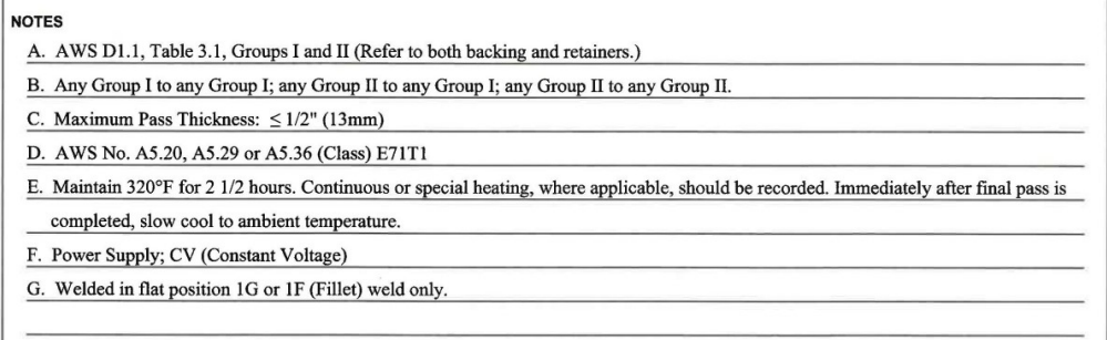
The notes section of this WPS, shown in Figure 18.5, contains general information to clarify what is contained in the WPS. This form includes the following notes:
A. AWS D1.1, Table 3.1, Groups I and II (Refer to both backing and retainers.)
B. Any Group I to any Group I; any Group II to any Group II; any Group II to any Group II.
C. Maximum Pass Thickness: ≤ ½” (13mm)
D. AWS No. A5.20, A5.29 or A5.36 (Class) E71T1
E. Maintain 320° F for 2 ½ hours. Continuous or special heating, where applicable, should be recorded. Immediately after final pass is completed, slow cool to ambient temperature.
F. Power Supply; CV (Constant Voltage)
G. Welded in flat position 1G or 1F (Fillet) weld only.
Page 2 Signature Block of a WPS
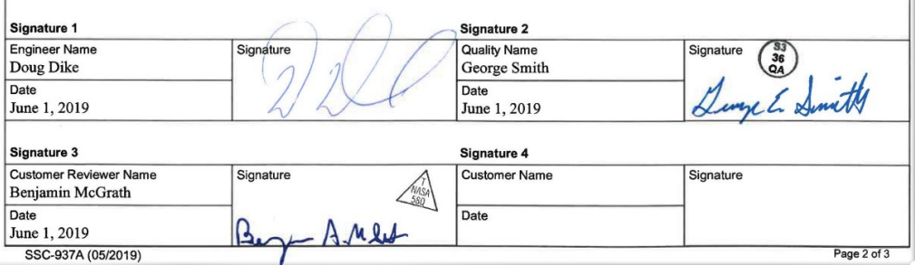
The signature block of the WPS, shown in Figure 18.6, contains the signatures of the organizational members who have reviewed and are approving the WPS and the date they approved it. This particular form includes space for the engineer’s name, the quality control officer’s name, the customer reviewer’s name, and the customer’s name.
The engineer, quality control officer, and customer reviewer have all signed this form. Under each person’s name is a space for the date, which for this form is June 1, 2019.
Attachments of a WPS
The next page of this NASA WPS has sketches of weld joints. This third page is likely the original from Revision A, and Revision B may have replaced the weld joint designs of Revision A with a new attachment. Figure 18.7 contains the obsolete joint designs, which are still cool to look at, while Figure 18.8 contains new joint designs for this WPS.
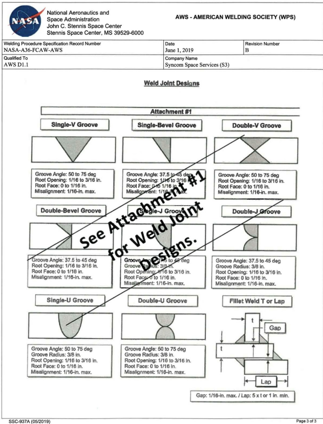
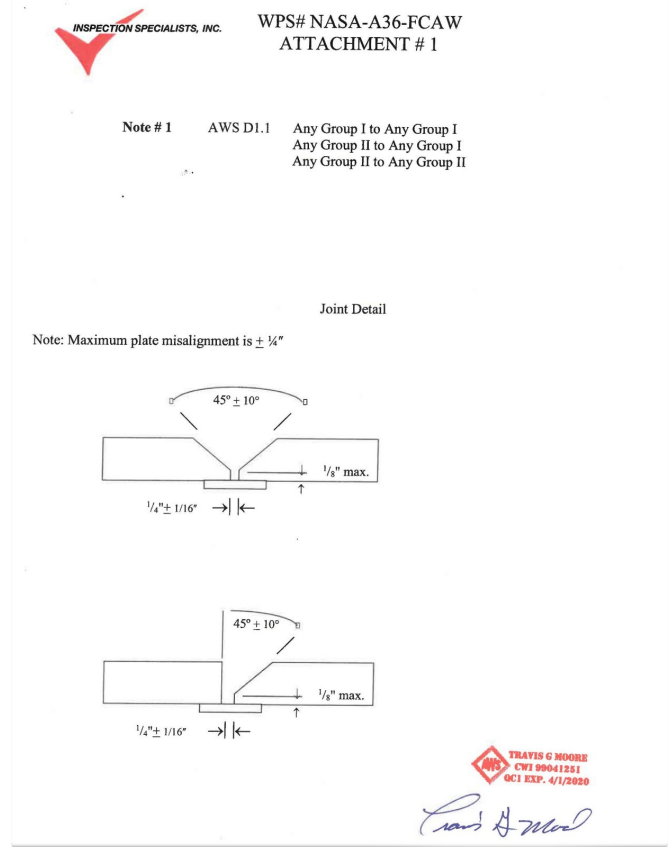
As you’ve seen, the first two pages of this WPS contain standard information. Joint designs and other information can be included with a WPS as attachments so the welder is provided all the information they need to weld in one single document.
WPSs are similar to blueprints in that they can look very different from company to company. However, they contain similar information and in a format that is similar enough between them that you can generally figure them out as you read more and more blueprints or WPSs.
Attributions
- Figure 18.1: Compliance is Mandatory John C. Stennis Space Center Flux Cored Arc Welding of Carbon Steel for ⅛-inch to Unlimited Plate Thickness by National Aeronautics and Space Administration, John C. Stennis Space Center in the Public Domain; United States government work
- Figure 18.2: Compliance is Mandatory John C. Stennis Space Center Flux Cored Arc Welding of Carbon Steel for ⅛-inch to Unlimited Plate Thickness by National Aeronautics and Space Administration, John C. Stennis Space Center in the Public Domain; United States government work
- Figure 18.3: Compliance is Mandatory John C. Stennis Space Center Flux Cored Arc Welding of Carbon Steel for ⅛-inch to Unlimited Plate Thickness by National Aeronautics and Space Administration, John C. Stennis Space Center in the Public Domain; United States government work
- Figure 18.4: Compliance is Mandatory John C. Stennis Space Center Flux Cored Arc Welding of Carbon Steel for ?-inch to Unlimited Plate Thickness by National Aeronautics and Space Administration, John C. Stennis Space Center in the Public Domain; United States government work
- Figure 18.5: Compliance is Mandatory John C. Stennis Space Center Flux Cored Arc Welding of Carbon Steel for ⅛-inch to Unlimited Plate Thickness by National Aeronautics and Space Administration, John C. Stennis Space Center in the Public Domain; United States government work
- Figure 18.6: WPS Signature Block by National Aeronautics and Space Administration, John C. Stennis Space Center in the Public Domain; United States government work
- Figure 18.7: Compliance is Mandatory John C. Stennis Space Center Flux Cored Arc Welding of Carbon Steel for ⅛-inch to Unlimited Plate Thickness by National Aeronautics and Space Administration, John C. Stennis Space Center in the Public Domain; United States government work
- Figure 18.8: Compliance is Mandatory John C. Stennis Space Center Flux Cored Arc Welding of Carbon Steel for ⅛-inch to Unlimited Plate Thickness by National Aeronautics and Space Administration, John C. Stennis Space Center in the Public Domain; United States government work
a person picked by company management with authority to speak and do things for the company
