19.3 Destructive Examination
David Colameco, M.Ed.
Basics of Destructive Examination
Destructive examination involves the destruction of a weldment to determine its mechanical properties and visually inspect a cross-sectional area of the weld. To imagine what a cross-sectional is, think of cutting a pipe in half: The exposed area of the pipe wall where you made your cut is the cross-sectional area. Some of us cut better than others; just think of the first time you torch cut something. For destructive examination the cuts are made as precisely as possible using an accurate cutting method and then preparing the surface to ensure that it is smooth for easier identification of discontinuities. See Figure 19.49 for an example of a surface that has been prepared for examination using macroetching, a process in which an acid is used to prepare the cross-sectional surface of a weld to see the grains and heat-affected zone of a weld.
Uses of Destructive Examination in Industry Today
Destructive examinations allow an inspector or fabricator to see what the inside of a weld looks like. Because destructive tests destroy the weldment, they are only performed on weldments made for qualification purposes. This qualification can be for a welding procedure, a filler metal, a welder qualification, or other qualifications or inspections.
Whenever you perform a code weld, everything from the filler metal, base metal, welding process, welding machine settings, and the welding technique are all qualified and listed on the Welding Procedure Specification (see Chapter 18). Filler metals, base metals, and welds are destructively tested using bend tests, tensile tests, and charpy V-notch tests depending upon the code requirements for qualifying a welding procedure. These are discussed in more detail in the following sections.
Bend Tests
Bend tests do exactly what their name implies: bend the weld. Welds on plates or pipes are cut in accordance with the welding code that is being used. The code will specify the dimensions of the bend test specimens along with the dimensions of the bend testing machine. An example bend testing machine is shown in Figure 19.39. It is a manual machine where the operator would have to use the lever to pump air pressure into the machine to apply a force down on the specimen to bend it.
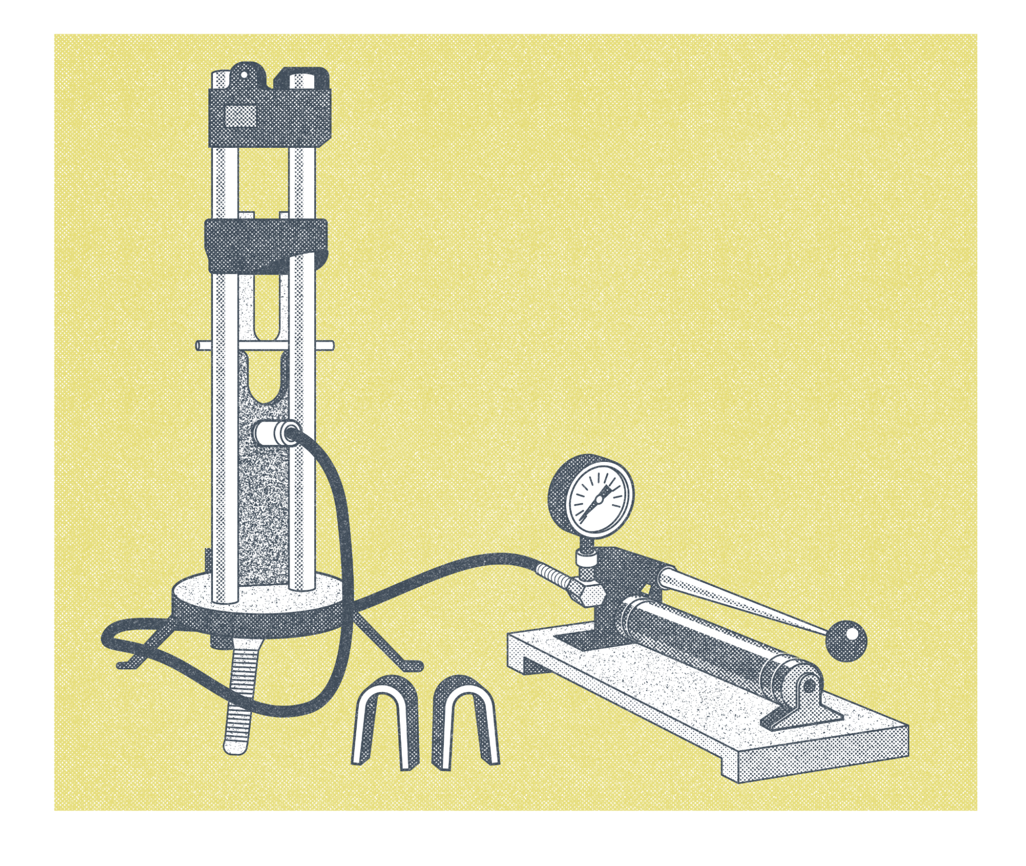
In Figure 19.39, in the middle of the machine portion with the plunger, you can see the straight metal specimen before it is bent sticking out. It also shows two bent specimens in the shape of upside down Us. Actual bend test specimens are shown in Figure 19.40. Bend tests evaluate how well the welds are fused to each other and if the metal is solid throughout without any defects. Defects are discontinuities such as tears, slag inclusions, and porosity (that are larger than the acceptable sizes listed in the applicable code).
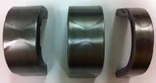
Figure 19.40 shows bend specimens of a double V groove weld. The inspector looks for fusion of weld passes to each other and to the base material. For tests on welds made with processes that have slag, such as SMAW and FCAW, they are reviewed for slag inclusions. Tungsten inclusions would be looked for if GTAW or plasma arc welding (PAW) were used. (PAW is not discussed in this book, but it is worth mentioning that that process also uses a tungsten electrode.)
Each code will specify the acceptable size and number of discontinuities that can exist in a specimen. Codes also specify any follow-up steps if a bend test fails. In some cases, additional bend test specimens may be used as specified in the code. In other cases the weld test would need to be redone and new samples tested.
Tensile Tests
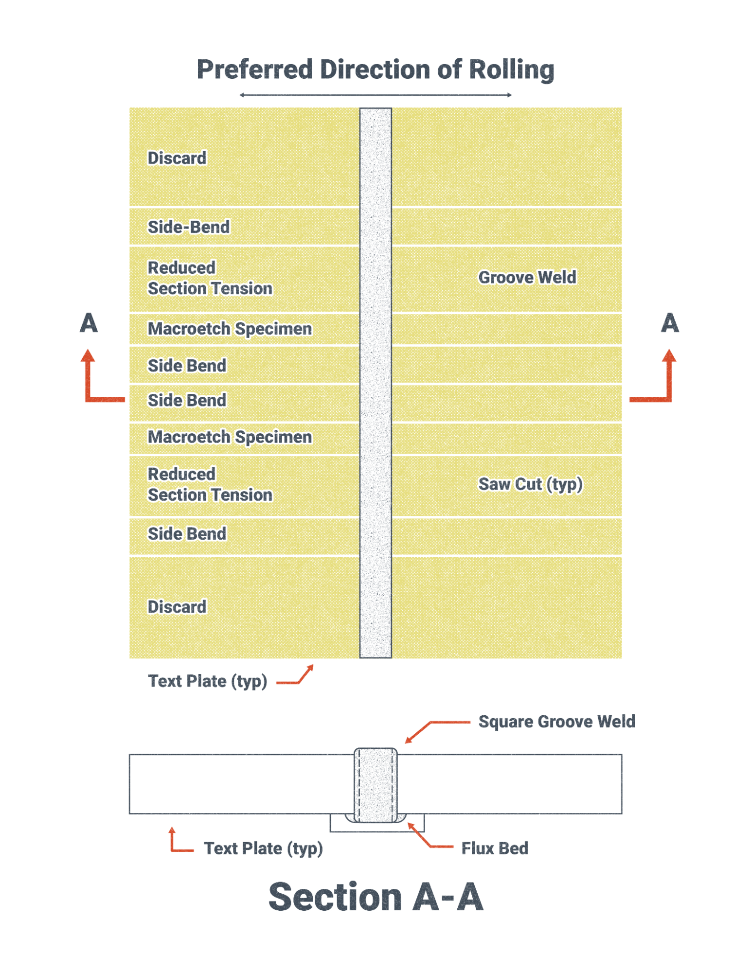
Tensile tests measure the tensile strength of a portion of the weldment. For filler metal test specimens, as specified in the code it’s being tested to, typically the entire sample is weld metal. For test specimens that are used to qualify welding procedures or welders, those samples include both base metal and filler metal. Figure 19.41 shows a test plate and the locations where test specimens are cut from the test plate based on dimensions specified by the code being used—in this case, AWS D1.5 Bridge Welding Code. (structural code tests are similar for our discussion).
Figures 19.42 and 19.43 show test specimens that have threads on the ends for placement in a tensile testing machine. The dimensions and tolerances of the specimen ensure consistent tests and tests that are designed to fail in the reduced section.
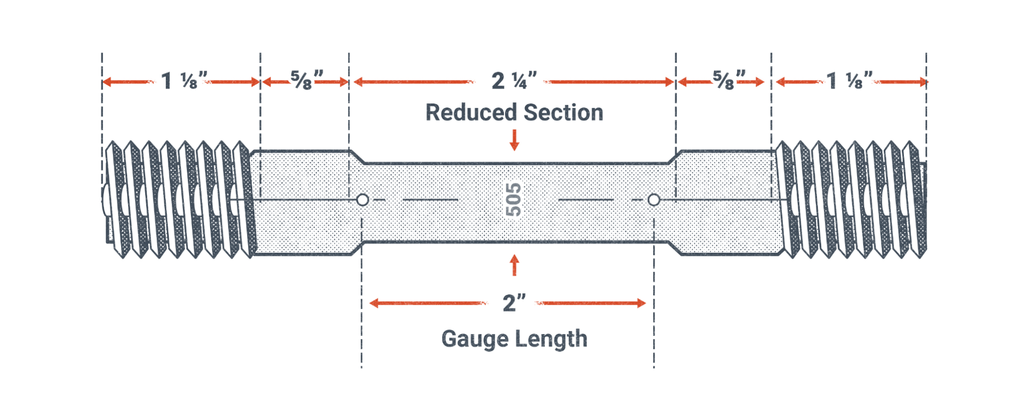
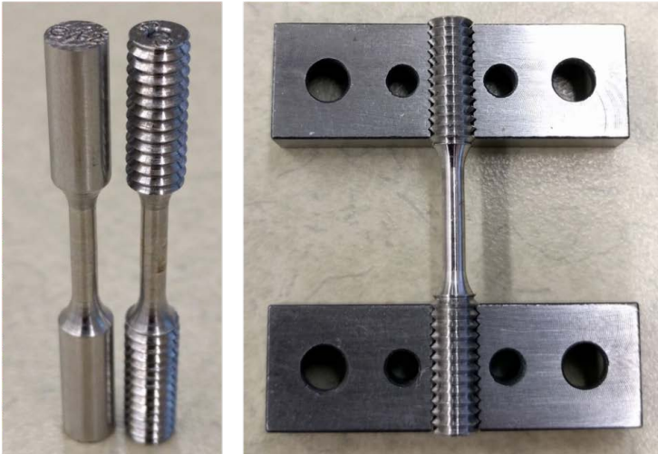
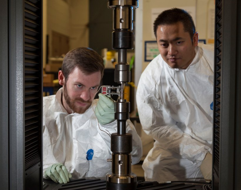
Figure 19.44 shows a tensile test machine with the test specimen in the center. The technician on the left side is holding a strain gauge, a tool that measures the change in length of the specimen and, using the original length before a load was applied, can calculate the strain, which equals the change in length divided by the original length. The strain gauge is removed from the specimen before it breaks to prevent any damage to the tool, as it is an expensive piece of equipment. A computer system is typically used to collect the data from the test setup. The computer program, using the material properties of the specimen’s material, and the data from the test in progress will typically alert the technician about when to remove the strain gauge.
The results of the tensile test are compared to the requirements of the relevant code it was performed to. If the test results are within the ranges specified in the code, the test passes.
Charpy V-Notch Tests
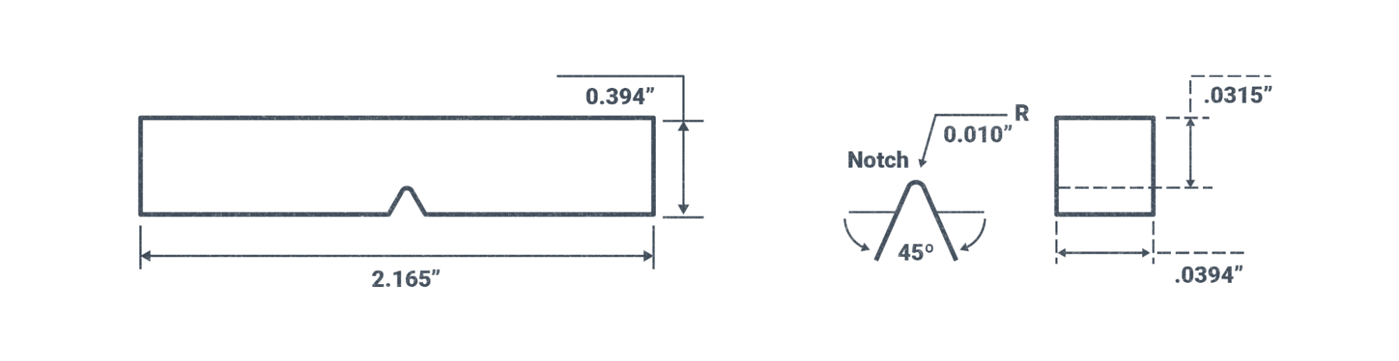
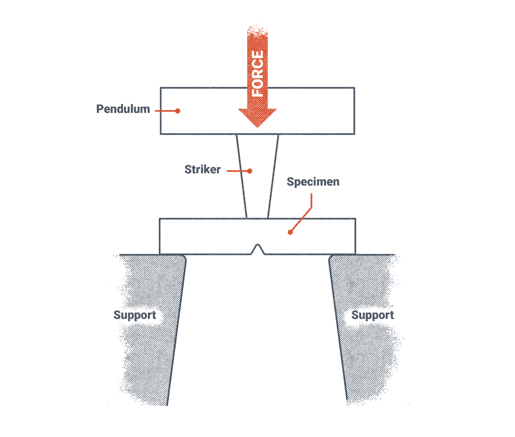
Charpy V-notch tests measure the energy that is absorbed by a test specimen with a V notch in it. A hammer is raised to a specific height and is then released to impact the specimen. The mass (commonly referred to as weight) of the hammer and its height when it is swung towards the specimen determine the energy of the hammer at impact.
The specimen absorbs some energy and the rest of the energy is used by the hammer to travel past the specimen and continue on its arc of travel until it reaches a maximum height. The machine will record the maximum height of the hammer post-impact, which is used to calculate the energy absorbed by the specimen.
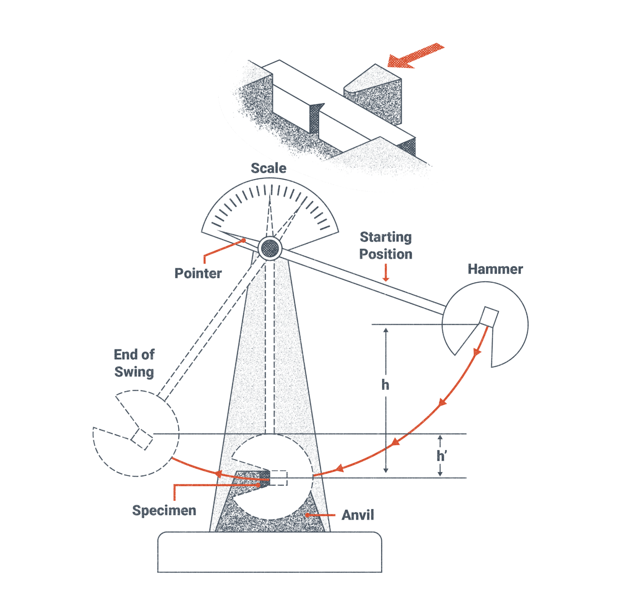
As seen in Figures 19.46 and 19.47, the force of the hammer (also labeled striker) strikes the specimen opposite of the V-notch. The V-notch provides a weak point where failure of the specimen will occur. Similar to the tensile and bend tests, the code being applied for the charpy V-notch test has requirements for the dimensions of the test specimen, specifications for the testing machine, temperatures of the test specimen, and a required range of energy that must be absorbed by the specimen in order for it to pass the test. Materials that cannot absorb the specified energy in the standard are not as strong as they need to be and therefore are at higher risk of failure when the fabrication is subjected to loads.
The successful and thorough fusion of the welds measured in the bend tests, along with the measurement of the tensile strength of the weld using the tensile test and the tests of the energy that is absorbed by the weld all, provide information about the mechanical properties of the welds that are required for qualification of welding filler metals, welding procedures, and welders and welding operators per the codes being used.
Etching Exposed Surfaces for Visual Inspection
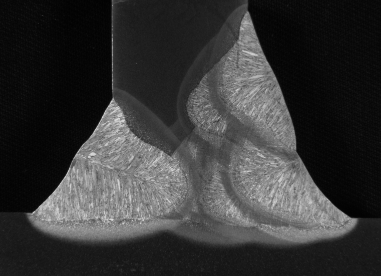
Etching is a destructive test that is used to expose the detail of a cross section of a weld. Figure 19.48 shows the cross section of a T-joint. If you look at the cut surface, you see it resembles a T; that T shape is the cross section of the T-joint. After the cut is made, the surface is prepared so that it is smooth and an acid is applied to the surface to bring out the detail of the metal grain structure (a process known as macroetching).
Figure 19.48 is an excellent, high-quality example of an acid etch test. The grain structure can be seen in the individual weld beads.
Inspectors performing acid etch tests must take care when handling acids and acid solutions. Never use acids without permission from your instructor and follow the instructions and precautions on the acid container.
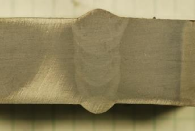
Figure 19.49 is a picture of an acid etch of a butt joint as it would appear in normal lighting. The individual weld beads and the heat-affected zones of each weld bead are visible, however the grains within the weld are not readily visible.
Attributions
- Figure 19.39: Bend Test Machine by Nicholas Malara, for WA Open ProfTech, © SBCTC, CC BY 4.0
- Figure 19.40: Weldability by U.S. Department of Energy, Advanced Reactor Concepts Program in the Public Domain; United States government work
- Figure 19.41: Test Specimen Locations by Nicholas Malara, for WA Open ProfTech, © SBCTC, CC BY 4.0
- Figure 19.42: Standard Tensile Test Specimen by Nicholas Malara, for WA Open ProfTech, © SBCTC, CC BY 4.0
- Figure 19.43: Left: picture of specimens after machining, Right: a specimen fit to grips by U.S. Department of Commerce, National Institute of Standards and Technology in the Public Domain; United States government work
- Figure 19.44: Aaron Bales, left, and Rob Panaro attach an extensometer to a tensile specimen. The extensometer gives an accurate measure of how much the specimen stretches during a tensile test. by U.S. Department of Energy, National Nuclear Security Administration in the Public Domain; United States government work
- Figure 19.45: Charpy Test Specimen Dimensions by Nicholas Malara, for WA Open ProfTech, © SBCTC, CC BY 4.0
- Figure 19.46: Charpy V-Notch Test Machine by Nicholas Malara, for WA Open ProfTech, © SBCTC, CC BY 4.0
- Figure 19.47: Charpy Test Diagram by Nicholas Malara, for WA Open ProfTech, © SBCTC, CC BY 4.0
- Figure 19.48: Example macroetch of a T-joint mockup by U.S. Department of Transportation, Federal Highway Administration in the Public Domain; United States government work
- Figure 19.49: Commercial ER100 weld wire by U.S. Department of Energy, Oak Ridge National Laboratory in the Public Domain; United States government work
Destructive examination involves the destruction of a weldment to determine its mechanical properties and/or visually inspect a cross sectional area of the weld. Because destructive tests destroy the weldment, destructive tests are only performed on weldments made for qualification purposes.
The area of an object or weldment of the surface that is created when it is cut. When you cut a piece of butter off of a stick of butter, the cross sectional area is a square if you cut it perpendicularly straight up and down.
Defects are discontinuities such as tears, slag inclusions, and porosity, that are larger than the acceptable sizes listed in the applicable code.
