20.2 Welding Carbon Steels
David Colameco, M.Ed.
Basics of Welding Carbon Steels
The majority of carbon steel comes in shapes you are familiar with or will become familiar with while welding and fabricating; these include plates, pipes, H-beams, and C-channels. As with any material or process, the WPS and blueprints will provide you with the instructions you need to complete the fabrication to the required specifications. If the WPS or blueprint has something that isn’t clear to you, stop and ask a colleague or supervisor for clarification. Spending a few minutes to clarify something is better than spending an hour or more on rework.
Steels can be hot rolled, cold rolled, quenched and tempered, or processed in other ways to achieve the desired properties. When you weld, you are destroying those treatments and mechanical workings of the base material because the metal melts within the weld pool, returning the metal to its original state prior to treatment. In areas where the base material does not melt, there is a heat-affected zone (HAZ) where grain growth, allotropic change, and absorption of elements into the crystal structure can occur. The heat applied to the base metal in the HAZ will change the mechanical properties of the base material and result in a weld with material properties that are less than desired. The end result could be failure of the weld joint due to cracking, which is why following a WPS is so important: as welders, we do not want structural failure to occur because of the weld.
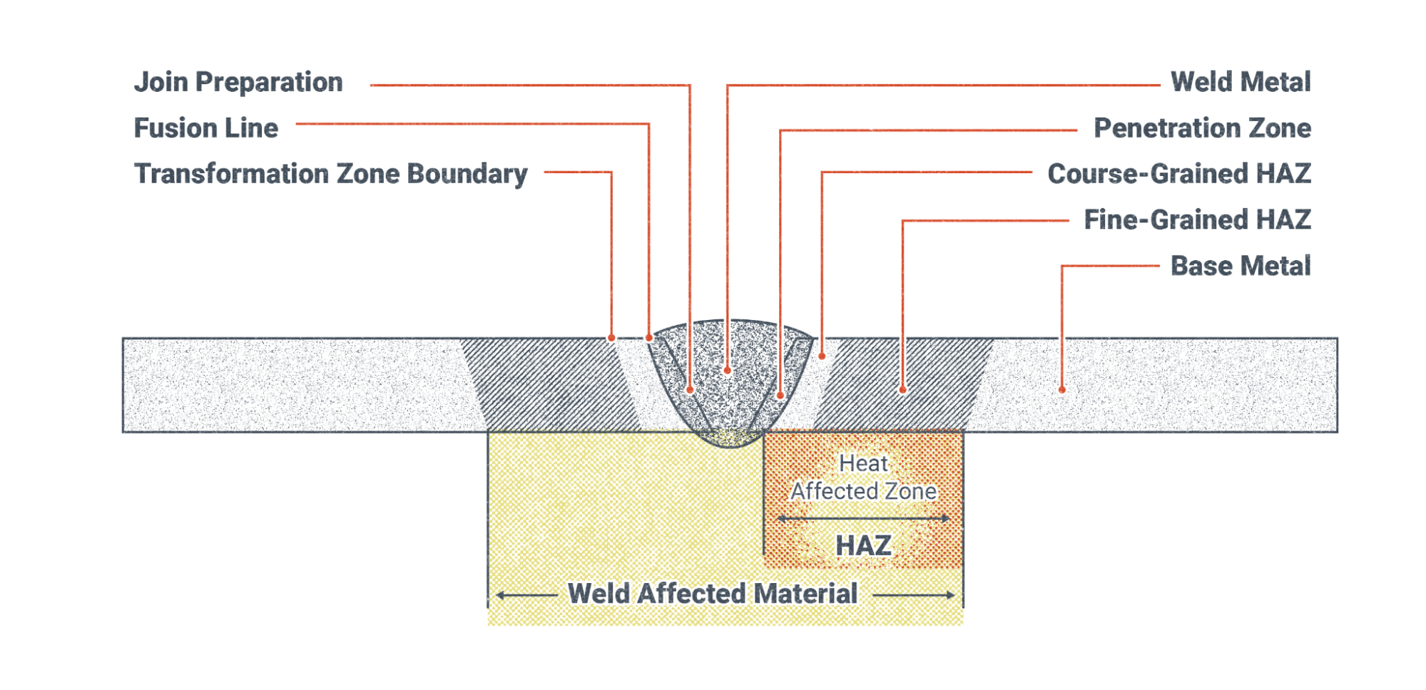
The HAZ is a complex set of subdivided zones, as shown in the V-groove butt joint in Figure 20.6. The weld metal is at the center, followed by a penetration zone directly next to the weld metal that represents the melted base material that fuses with the weld metal. Moving further outward, next is the coarse-grained HAZ that experiences elevated temperatures from welding, but not temperatures hot enough to melt the metal. In this zone the heat causes the metal grains to grow, which means they become more coarse. The further away we move from the weld bead itself, the less heat there is in the base metal due to dissipation of heat. Therefore the fine-grained HAZ has grains that are affected by the heat, but they grow to a lesser extent than in the coarse-grained HAZ. This zone may have been tempered from the heat. And finally, outside of the fine-grained HAZ is the base metal, which may have been heated up but has not undergone any mechanical property changes.
It is important to note that other sources may break up the HAZ into a more detailed structure with further subdivisions. For the purposes of this chapter, this level of detail about the HAZ is adequate.
Steels from the mill are processed through cold rolling and hot rolling. Rolling is a process where the steel is forced through rollers to flatten it out. Finer grained steel structures have a higher toughness. Figure 20.7 shows two metals being rolled together. The processes for cold and hot rolling a single piece of steel are similar.
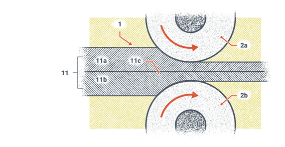
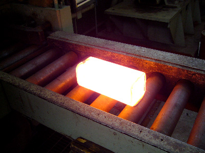
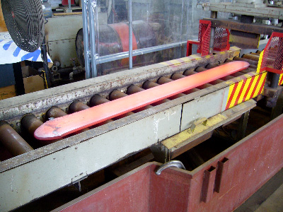
Figure 20.8 shows a hot ingot that is being sent to a hot rolling process. This ingot of steel will be sent back and forth through a set of rollers that will gradually get closer together so the steel flattens out. Figure 20.9 shows the results of the hot rolling process that has occurred to the same ingot.
These cold and hot rolling processes break the larger grain structures into a finer grain structure. Welding on steels that have been cold or hot rolled to form finer grains will result in a coarse-grained structure in the HAZ. Post-weld heat treatment (PWHT) will relieve some of the residual tensile stresses that exist from the weld metal shrinking after it cools. Temperatures for PWHT are carefully controlled in duration and magnitude based on the base material. Too high a temperature can transform the metal’s crystalline structure into something undesirable where there is a loss of strength. And being held in a temperature for too long can cause grain growth, which results in reduced toughness of the metal.
Determining Carbon Steel Types
Generally, whenever you are welding you should know which metal or metal group you are welding so you can produce a successful weld. Ideally you would know the metal composition because the metal is labeled in one form or another, but you could also use a device, called a spectrometer, that analyzes the metal by its light emissions. Figure 20.10 shows a handheld spectrometer used for analyzing pavement that is similar to but larger than the kind used to analyze metal.

Another method welders can use to identify the type of steel they have in front of them is a file test. Table 20.1 contains information on the Brinell hardness number (BHN) of steel, which is one scale used by metallurgists to rank the hardness of metals. Note that iron becomes steel with the addition of carbon.
| File Reaction | Brinell Hardness | Type of Steel |
|---|---|---|
| File bites easily into metal | 100 BHN | Mild Steel |
| File bites into metal with pressure | 200 BHN | Medium Carbon Steel |
| File does not bite into metal except with extreme pressure | 300 BHN | High-alloy Steel – High-carbon Steel |
| Metal can only be filed with difficulty | 400 BHN | Unhardened Tool Steel |
| File will mark metal but metal is nearly as hard as the file and filing is impractical | 500 BHN | Hardened Tool Steel |
| Metal is harder than file | 600 + BHN | Unable to determine |
Note. From Operator’s Circular Welding Theory and Application, Table 7-6 (United States Army, 1993).
For comparison, Table 20.2 lists the carbon contests of steel and cast iron.
| Item | Approximate % of Carbon | Condition of Incorporated Carbon |
|---|---|---|
| Pig Iron | 4.0 | Free and Combined |
| White Cast Iron | 3.5 | Mostly Combined |
| Grey Cast Iron | 2.5 to 4.5 | 0.6–0.9% free, 2.6–2.9% combined |
| Malleable Cast Iron | 2.0 to 3.5 | Free and Combined |
| Tool Steel | 0.9 to 1.7 | All Combined |
| High-carbon Steel | 0.5 to 0.9 | All Combined |
| Medium-carbon Steel | 0.3 to 0.5 | All Combined |
| Cast Steel | 0.15 to 0.6 | All Combined |
| Low-carbon Steel | Up to 0.3 | All Combined |
Note. From Operator’s Circular Welding Theory and Application, Table 7-7 (United States Army, 1993).
Another identification test that can be performed in the shop is a spark test. This one is conducted by grinding a metal sample on a grinding wheel and observing the sparks. Figure 20.11 shows a black-and-white image of spark test results, and color images are available online through an internet search.
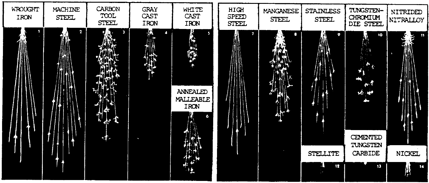
| Metal | Volume of Stream | Relative length of stream (in.) | Color of stream close to wheel | Color of stream near the end of the stream | Quantity of Spurts |
|---|---|---|---|---|---|
| Wrought Iron | Large | 65 | Straw | White | Very few |
| Machine Steel (A1S1 1020) | Large | 70 | White | White | Few |
| Carbon Tool Steel | Moderately large | 55 | White | White | Very many |
| Grey Cast Iron | Small | 25 | Red | Straw | Many |
| White Cast Iron | Very small | 20 | Red | Straw | Few |
| Annealed Malleable iron | Moderate | 30 | Red | Straw | Many |
| High-Speed Steel (18-4-1) | Small | 60 | Red | Straw | Extremely few |
| Austenitic Manganese Steel | Moderately Large | 45 | White | White | Many |
| Stainless Steel (Type 410) | Moderate | 50 | Straw | White | Moderate |
| Tungsten-Chromium Die Steel | Small | 35 | Red | Straw | Many |
| Nitrided Nitralloy | Large (curved) | 55 | White | White | Moderate |
| Stellite | Very small | 10 | Orange | Orange | None |
| Cemented Tungsten Carbide | Extremely small | 2 | Light orange | Light orange | None |
| Nickel | Very small | 10 | Orange | Orange | None |
| Copper, Brass, Aluminum | None | Not applicable | Not applicable | Not applicable | None |
Note. From Operator’s Circular Welding Theory and Application, p. 7-13 (United States Army, 1993).
Lastly, a final identification test is the chip test, conducted by using a sharp cold chisel to remove material. Material may be small broken pieces or one long strip. Table 20.4 describes the chip characteristics of different cast irons and steels. This is useful information for a welder if they have an unknown metal that they may think is cast iron or steel and are looking for a relatively easy way of determining its type.
| Metal | Chip Characteristics |
|---|---|
| White Cast Iron | Chips are small, brittle fragments. Chipped surfaces not smooth. |
| Gray Cast Iron | Chips are about ⅛ inch in length. Metal not easily chipped; therefore, chips break off and prevent smooth cut. |
| Wrought Iron | Chips have smooth edges. Metal is easily cut or chipped, and a chip can be taken off as a continuous strip. |
| Low-carbon and Cast Steel | Chips have smooth edges. Metal is easily cut or chipped, and a chip can be taken off as a continuous strip. |
| High-carbon Steel | Chips show a fine grain structure. Edges of chips are lighter in color than chips of low-carbon steel. Metal is hard but can be chipped in a continuous strip. |
Note. From Steelworker, Volume 1, Table 1-4 (Naval Education and Training Professional Development and Technology Center, 1996).
Knowing the temperature of steel is important to a welder. Accurate measurements of metal surface temperatures can be taken in different manners: using a handheld industrial infrared thermometer, using heat sticks to determine if the temperature has exceeded the value of the stick material, or—the least accurate method—visually observing the color of the steel. Table 20.5 provides the colors steel may emit at different temperatures.
| Color | Temperature (°F) | Temperature (°C) |
|---|---|---|
| Faint red visible in dark | 750 | 399 |
| Faint red | 900 | 482 |
| Blood red | 1050 | 565 |
| Dark cherry | 1075 | 579 |
| Medium cherry | 1250 | 677 |
| Cherry or full red | 1375 | 746 |
| Bright Red | 1550 | 843 |
| Salmon | 1650 | 899 |
| Orange | 1725 | 940 |
| Lemon | 1825 | 996 |
| Light Yellow | 1975 | 1079 |
| White | 2200 | 1204 |
| Dazzling White | 2350 | 1288 |
Note. From Steelworker, Volume 1, Table 2-1 (Naval Education and Training Professional Development and Technology Center, 1996).
Uses of Carbon Steel in Industry Today
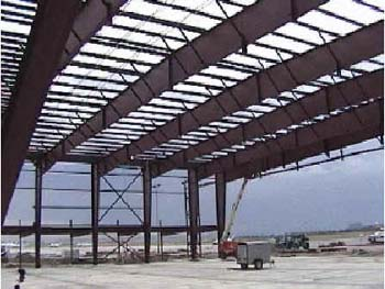
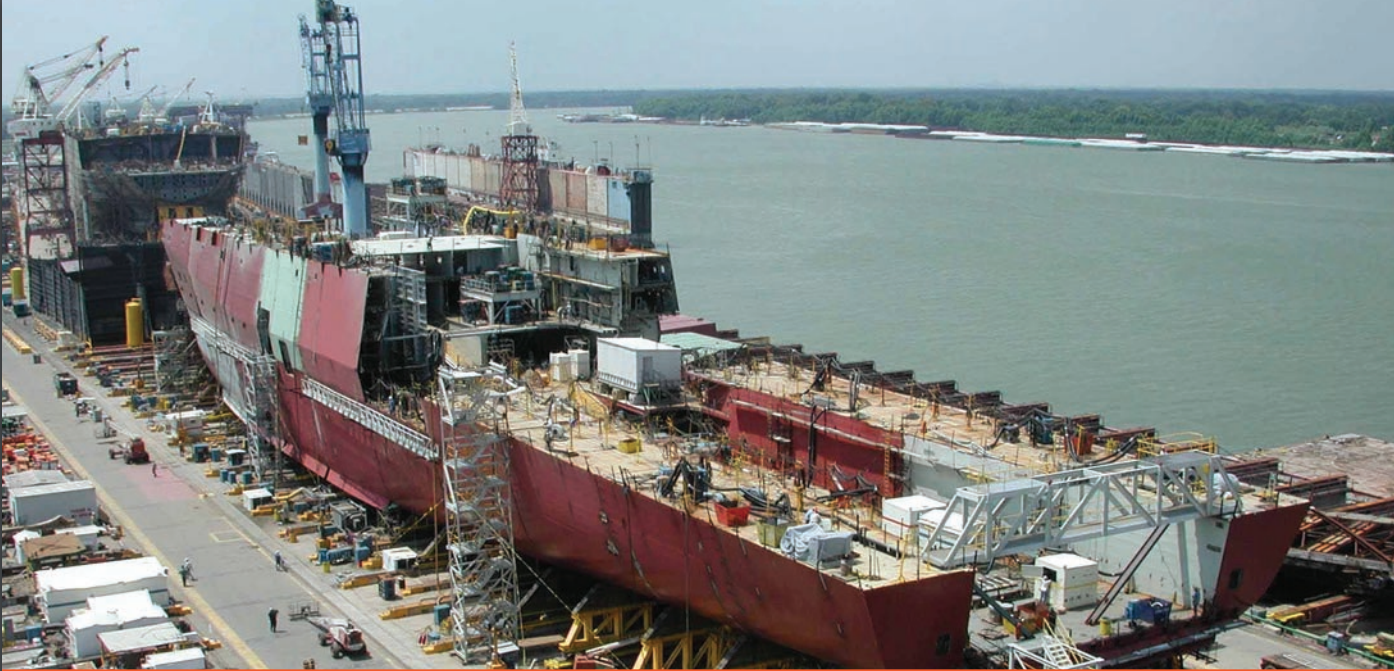
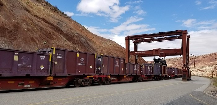
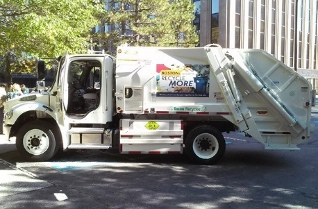
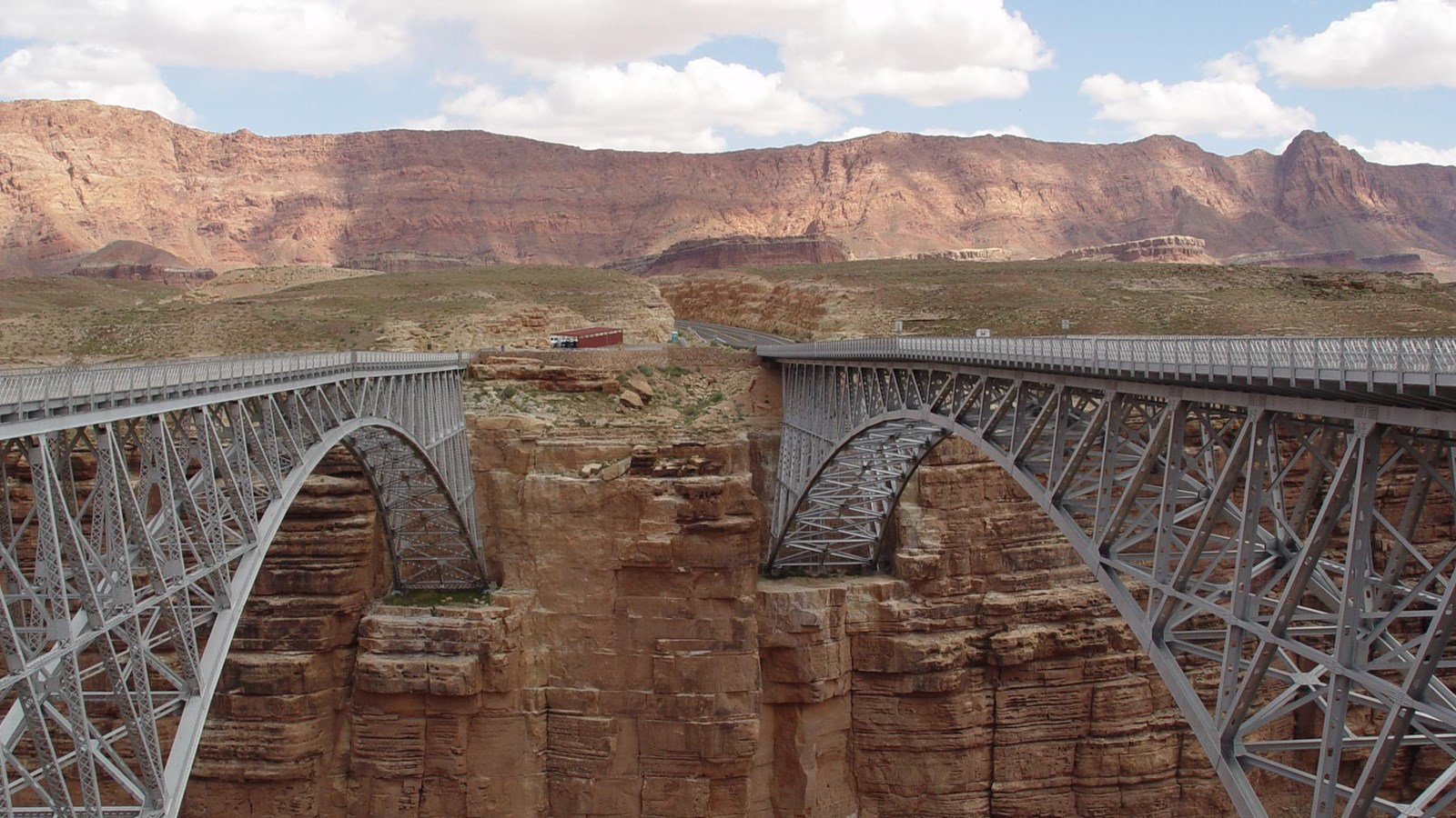
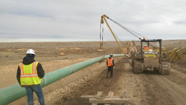
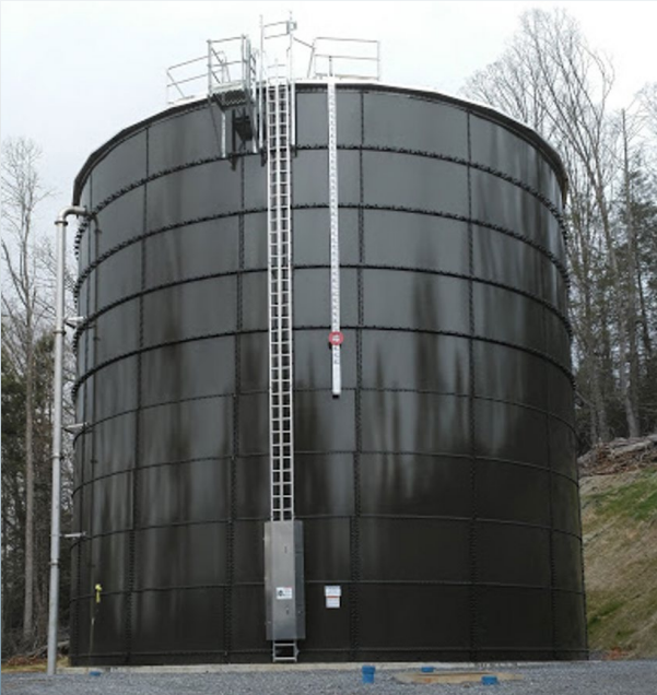
Everything from buildings, ships, bridges, railroads, cars and trucks, shelves, water heaters, pressure vessels, tanks, pipes, home appliances such as washing machines and dryers, and many more items that improve our everyday lives are made out of carbon steels or have carbon steel components.
Welding Processes Used With Carbon Steel in Industry Today
Generally speaking, all welding processes at your local community college or vocational school are applicable to welding carbon steels. The material in this section is not exhaustive, but it lists the welding processes you will encounter as a student in your technical program for welding carbon steels. Table 20.6 offers a very general overview of how the processes are used, but remember that there are always exceptions to generalizations. How each process is used for carbon steel is discussed in more detail below.
| Welding Process | General Use |
|---|---|
| Shielded metal arc welding (SMAW) | Fabrication in shop and field, repairs, tack welding |
| Flux-cored arc welding, gas-shielded (FCAW-G) | Fabrication in the shop, repairs, used on dirtier parts |
| Flux-cored arc welding, self-shielded (FCAW-S) | Fabrication in the field, repairs |
| Gas metal arc welding (GMAW) | Fabrication and repair on clean surfaces |
| Short circuit gas metal arc welding (GMAW-S) | Fabrication and repair on clean, thin surfaces |
| Gas tungsten arc welding (GTAW, aka TIG and Heliarc) | Fabrication and repair of all metals including high-quality welds such as specialty alloys and critical welds |
| Submerged arc welding (SAW) | Fabrication of thick materials in heavier industries such as bridge building, pipe fabrication, and very large fabrications |
Note. Heliarc is the original trade name by the Union Carbide Corporation
It is important that you learn to use as many welding processes as possible while in your welding program because many are used together in industry, such as using GTAW for root passes followed by SMAW on pipe welding. The next few sections provide a high-level overview of the welding processes that can be used to weld carbon steels. Please see the dedicated chapters on these respective welding processes for more information.
Shielded Metal Arc Welding
SMAW is a tried-and-true welding process that has relatively inexpensive equipment that can get into tight spaces to weld. The process has various electrode types of different alloys, tensile strengths, and sometimes hydrogen contents. Low-hydrogen electrodes are used for applications where cracking is an issue, such as when welding thick base materials. If low-hydrogen electrodes are not used, that hydrogen may not have enough time to diffuse out of the base material, which is what could lead to cracks. Use of low-hydrogen electrodes and even a PWHT may be used to reduce and remove hydrogen from the weldment. (Chapter 8 discusses SMAW in detail.)
Gas Metal Arc Welding
GMAW does not produce slag and is a higher deposition process than SMAW meaning that it can lay down more weld. GMAW has the ability to deposit more weld metal because the filler wire is continuously fed into the welding gun with the pull of the trigger. The drawback of GMAW is that it suffers from being susceptible to air drafts, which would blow away the shielding gas that is needed to protect the weld metal while it is hot from the elements such as nitrogen and oxygen that are in the air that would result in porosity in the weld. For this reason, GMAW is not a good candidate for field welding. (Chapter 10 discusses GMAW in detail.)
Flux-Cored Arc Welding
FCAW is a semiautomatic wire-feed process that is being adopted by welders in the field. This process has a self-shielded and a gas-shielded variation. The self-shielded FCAW, or FCAW-S, is similar to SMAW in that the electrode contains flux material that shields the weld from the air. The other variation is gas-shielded, or FCAW-G, which uses a cored electrode that has a flux in it and a shielding gas which together protect the weld from the air.
One question that you may want to ask is “Can I use a FCAW-S wire with a shielding gas if I run out of FCAW-G wire?” You certainly could set up a machine to do this, but it is not advised because the elements that are in the FCAW-S wire will not react with the air to form a slag as they are intended and will instead end up in the weld pool, which is likely to negatively affect the chemistry of the weld and, in turn, the mechanical properties of the weldment. This is similar to hauling construction materials in a compact car versus a truck: you can do it, but unintended damage is likely to occur. And know that if it is a code weld, you cannot use FCAW-S wire because it would not be listed on the WPS for a project intended for FCAW-G.
The benefits of using FCAW are that it has a higher deposition rate and even though the hydrogen levels in the electrode are not as low as some low hydrogen SMAW electrodes, it can still be considered a low-hydrogen process. The downside to FCAW is that it may not have the versatility that SMAW has for tight spaces. Also, the welding machine needs to be close by, as longer welding leads will suffer from worn out liners because the wire will rub more on the liner as it makes its way through the lead. (Chapter 9 discusses FCAW in detail.)
Gas Tungsten Arc Welding (GTAW)
GTAW is also used to weld carbon steels. This process produces high-quality welds due to the control the welder has over the heat input and the general welding process. GTAW welders are highly-trained professionals.
The downside to GTAW is that it is not a field welding process and is typically done in a shop due to the shielding gas being susceptible to drafts blowing it away. Like FCAW, the welding leads are short because the welding machine is typically close by. Also, GTAW suffers from a low deposition rate and it would take a very long time to fill groove welds that are more quickly and easily filled by SMAW, FCAW, and GMAW. For this reason, GTAW might be used for the root pass of a groove weld in a pipe butt joint and then the inter-passes and cover passes would be welded using another process. (Chapter 11 discusses GTAW in detail.)
Other Processes
As mentioned previously, sometimes multiple processes are used together, such as GTAW for the root pass on a pipe weld that’s followed by SMAW. Sometimes even GMAW and FCAW can be used in succession. If you have a particular welding industry in mind you want to work in upon graduating from your welding program, it is highly recommended that you apply to intern at a company or at the very least go on a company tour and find out what other welding processes they use. You might be surprised and find that you should learn an additional process you didn’t think was used in that industry.
While not covered in this book due to its limited instruction in community colleges, we should briefly discuss submerged arc welding (SAW). SAW is a process that is used to weld thick pieces of carbon steel together in bridge building and in the construction of very large weldments, making it worthwhile to introduce to you since you may encounter it during your welding career. The process uses a granular flux and is welded in the flat and horizontal positions only. Welding in the horizontal position requires the use of barriers that keep the flux covering the weld pool, because otherwise the flux would fall out of the weld joint.
Figure 20.19 shows SAW being performed on a very large weldment for underwater wind turbine foundations . Notice the granular flux that is used, which protects the weld. This flux is typically low-hydrogen and must be kept in an oven at about 150 degrees Fahrenheit to up to 550 degrees Fahrenheit. As implied in its name, the arc is submerged and you cannot see it. SAW is a neat process to use that you should try out if given the opportunity.
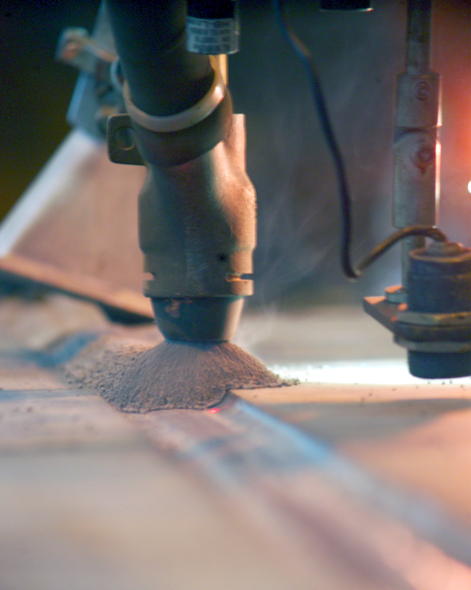
The flux in Figure 20.19 is covering the hot weld bead. Sometimes this flux will be recycled. Note that the welding does not emit fumes or smoke through the flux. SAW is used primarily on thick materials and can be used to make I-beams and pipes.
This section discussed the uses of carbon steel and the different welding processes used to weld it. The most important thing to take away is how important it is to learn more than one welding process because you may have to use multiple processes at a time during your career.
Attributions
- Figure 20.6: Weld Heat Affected Zone by Nicholas Malara, for WA Open ProfTech, © SBCTC, CC BY 4.0
- Figure 20.7: Rolling Cladded Steel by Nicholas Malara, for WA Open ProfTech, © SBCTC, CC BY 4.0
- Figure 20.8: Heat 67-V1-83 being hot rolled prior to first pass by U.S. Department of Transportation, Federal Highway Administration in the Public Domain; United States government work
- Figure 20.9: Heat 67-V1-83 being hot rolled after last pass by U.S. Department of Transportation, Federal Highway Administration in the Public Domain; United States government work
- Figure 20.10: Handheld XRF spectrometer by U.S. Department of Transportation, Federal Highway Administration in the Public Domain; United States government work
- Figure 20.11: Characteristics of sparks generated by the grinding of metals by Headquarters, Department of the Army in the Public Domain; United States government work
- Figure 20.12: Field-assembled building by U.S. Department of Labor, Occupational Safety and Health Administration in the Public Domain; United States government work
- Figure 20.13: Shipbuilding and Ship Repair by U.S. Environmental Protection Agency in the Public Domain; United States government work
- Figure 20.14: Sealed steel containers are loaded onto railcars at the Moab Uranium Mill Tailings Remedial Action Project site in preparation for transport of uranium mill tailings to the Crescent Junction disposal cell, 30 miles north of Moab. by U.S. Department of Energy, Office of Environmental Management in the Public Domain; United States government work
- Figure 20.15: Airflow Deflector Side Guard by U.S. Department of Transportation, Federal Highway Administration in the Public Domain; United States government work
- Figure 20.16: View of the historic (left) and modern (right) Navajo Bridge by U.S. Department of the Interior, National Park Service in the Public Domain; United States government work
- Figure 20.17: A pipeline being lowered into the trench by U.S. Department of Transportation, Pipeline and Hazardous Materials Safety Administration in the Public Domain; United States government work
- Figure 20.18: Erwin Water Storage Tank Replacement by U.S. Environmental Protection Agency, Office of Ground Water and Drinking Water in the Public Domain; United States government work
- Figure 20.19: UP schweissen WEA 00037 by Martinhannes is released under CC BY-SA 4.0
Carbon steel is any of the various steel alloys whose primary chemical elements are iron and carbon in varying amounts.
A change in the crystal structure of a metal, i.e. from Body Centered Cubic to Face Centered Cubic.
The act of adding (depositing) metal into a weld joint. Deposition sometimes refers to the deposition rate or amount of deposition per unit time.
