5.1 Welding Power
David Ridge
Components of Electricity
Disclaimer: The purpose of this section is to teach you about electricity only inasmuch as it applies to welding. The subject of electricity and all the ways we use it is a much broader topic and not the focus of this chapter. Every effort will be made to keep the discussion narrowly focused on how electricity is used to weld.
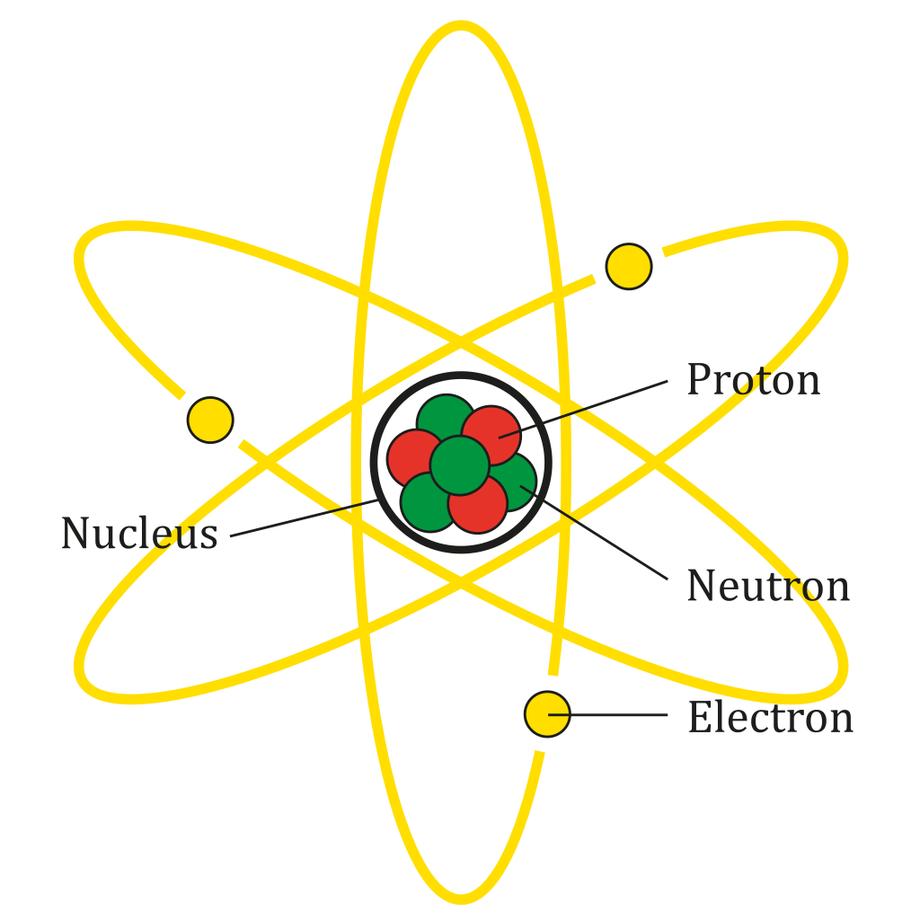
To start, all matter is made up of atoms. Atoms have three main parts: protons, neutrons, and electrons. The protons and neutrons of an atom are clustered together in a little ball at the center of the atom called the nucleus. The electrons of an atom circle the nucleus in tiny orbits. Any given material is determined by the number of protons, neutrons, and electrons in the atoms that it’s composed of.
Each of the three parts of an atom has a different electrical charge. Protons have a positive electrical charge, neutrons have no electrical charge, and electrons have a negative electrical charge. If an atom has more protons than electrons, then the overall electrical charge of the atom is positive, and vice versa.
The atoms in certain materials have weak bonds with their electrons, which allows the electrons to travel to and from the other atoms in the material. These materials are called conductors, and the more readily a conductor allows the movement of electrons between atoms, the better of a conductor it is. This is important because electricity, also called an electric current, can be described as the movement, or flow, of electrons from one atom to another in a conductor.
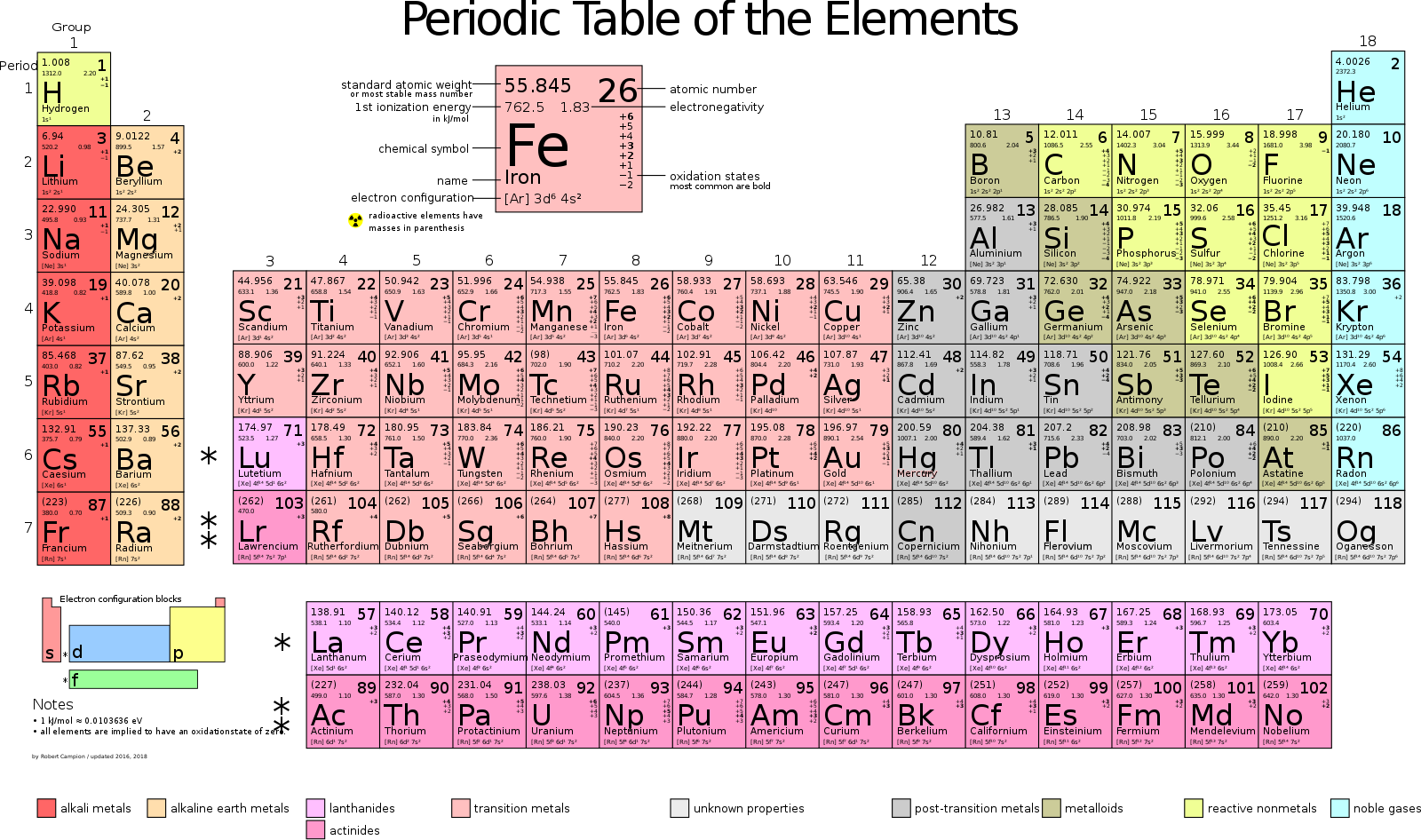
Some common conductors include iron (atomic symbol Fe) and copper (atomic symbol Cu).
There are some materials, called insulators, that resist the flow of electricity, meaning that they do not allow electricity to flow through them very well, or even at all in some cases. Insulators are just as important to how we use electricity as conductors, and you will often find conductors and insulators used together. For example, a power cable is a copper conductor wrapped in a rubber insulator for safety. This keeps anyone from coming in contact with a dangerous electric current.
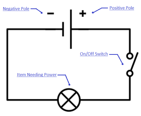
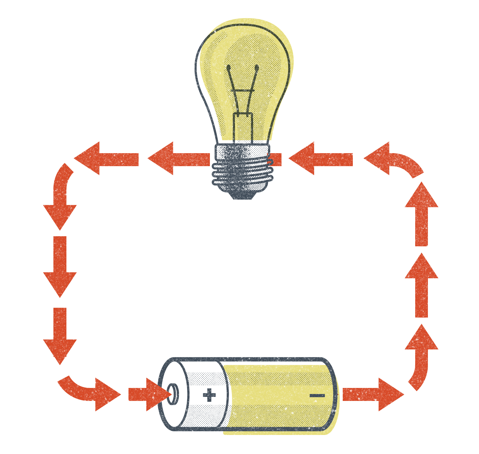
When talking about the flow of electricity, we say that an electric current flows in a circuit. This means that the electrons are flowing in a cyclical path. In fact, without a complete circuit to follow, electrons won’t flow at all. When electricity is flowing in a completed circuit, we say that the circuit is “closed.” When there is a break in the circuit (and electricity isn’t flowing), we say that the circuit is “open.”
There are a number of terms that describe and measure the flow of electricity. The most common for welders to use and hear are voltage, amperage, wattage, and ohms. Of these terms, voltage, and amperage will be the most important for you to understand as a welder because welding machine settings are based on these.
Volts/Voltage
A volt is a measure of electrical “pressure.” If we think about electricity flowing in a conductor like water flows in a hose, voltage can be compared to the water pressure. In a similar way to how the amount of water pressure determines how much force the water is pushed through a hose, voltage determines the amount of electromotive force that moves the electrons through a conductor.
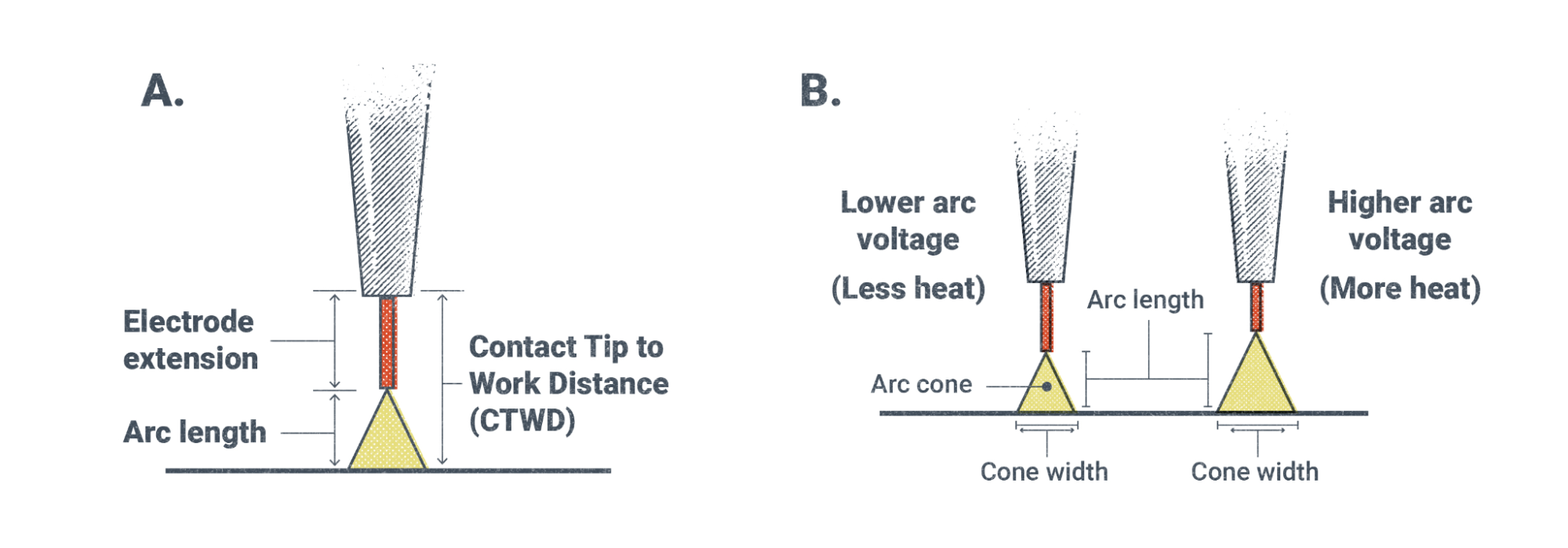
In terms of welding, voltage is important for two primary reasons. First, voltage determines the actual temperature of the arc and, thereby, the weld pool. This, in turn, determines how fluid the weld puddle is. Voltage and amperage must be balanced when making a weld. So if you need your weld to be more fluid and spread out easier, you either need more voltage or less amperage.

The second reason voltage is important in welding is that voltage is needed to initiate and maintain the arc. In the case of SMAW and GTAW, there is no voltage setting on your welding machine; instead, as the welder, you control the voltage by physically manipulating the arc length. This is because these processes run on what is called constant current welding power. The longer the arc, the more voltage the welding machine will output to maintain it. Conversely, if you need less voltage, you can hold a shorter arc length to reduce the amount of voltage. In the case of the wire-feed welding processes, there is a control setting for your voltage on the machine. The machine automatically controls the voltage during welding to maintain a consistent arc length. If you need a longer or shorter arc length, you would adjust the voltage up or down on the welder. These processes use constant voltage welding power. The different types of welding power and ways of adjusting voltage are discussed in more depth later in this chapter and in the respective welding process chapters.
Open-circuit Voltage
When using processes like SMAW and scratch-start GTAW, you may notice the voltage display on your welding machine hovering at or around 80V. This voltage reading is what is called open-circuit voltage, as this is the voltage in the system when the welding circuit is open and electricity is not flowing. Processes like SMAW and GTAW use constant current welding power (discussed in more detail later in this chapter), and it takes a significant amount of voltage to initiate the arc. Once the arc is initiated though, the voltage drops down to a lower output called the welding voltage or operating voltage, which is usually between 20V and 40V as determined by how the welder maintains the arc length.
The setting of 80V for the open-circuit voltage was developed as a sort of safety mechanism. It provides enough voltage to initiate the arc but not enough to cause serious harm to a person if they came in contact with a live part of the welding circuit. Anything below 80V is not enough for the electrical current to penetrate the outer layer of skin, though it still wouldn’t feel good.
Remember that large amounts of electricity are used when welding and that the danger of electrical shock is always present. The electrodes for SMAW and scratch-start GTAW are always electrically “hot” when attached to the machine and the power is on. Always be aware of your surroundings, and don’t put yourself in a position where you could become part of a live electrical circuit. One safety tip is to always wear gloves when handling electrical components.
Amps/Amperage
An amp (or ampere) is a measure of the number of electrons flowing in a circuit. In a way, you could say that amperage is a measure of the “volume” of an electric current in a system or how much of a current there is. Going back to our example of water in a hose, the amperage in a circuit can be compared to the volume of water flowing in the hose.
Amperage is important to welding because it determines the amount of heat energy is being applied to the weld. Heat is different from temperature in that temperature is a measure of how hot or cold something is while heat is a measure of the amount of energy something has. For example, a match and a bonfire burn at the same temperature, but the bonfire has significantly more heat energy.
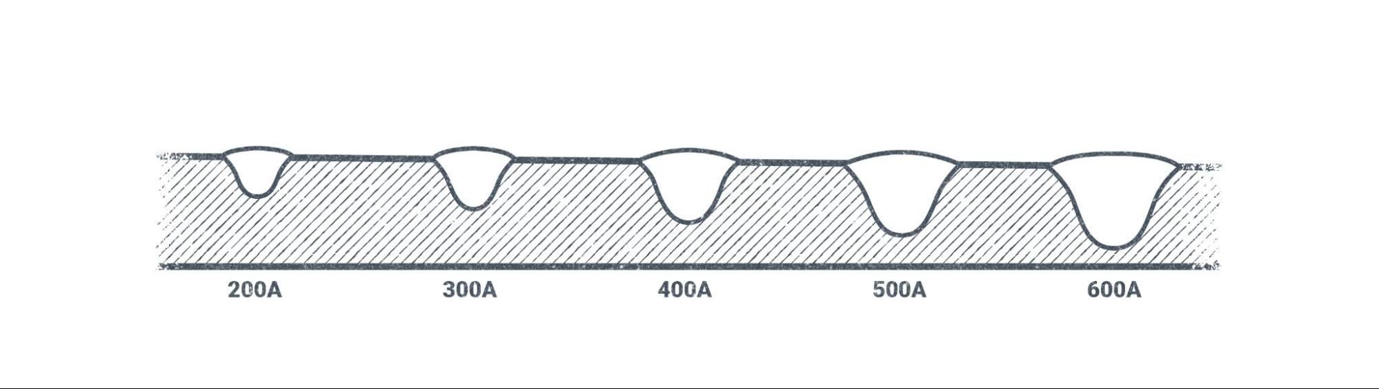
This concept is important for welding because the more heat energy applied to a weld, the better the weld penetration into the base metal. In general, the amount of amperage being used to make a weld correlates to the amount of weld penetration. Higher amperage means more penetration, and lower amperage means less penetration. The ability to adjust weld penetration characteristics is important for welding on metals of different types and thicknesses. For many processes that use consumable electrodes (electrodes that become part of the weld), adjusting the amperage also affects the rate at which these filler metals are deposited and, therefore, the speed at which the weld is made.
For processes like SMAW and GTAW, there is an amperage control setting on the welding machine. For the wire-feed processes, the amperage is tied to the wire-feed speed (wfs) control, which adjusts the speed at which the wire is fed through the system.
Watts/Wattage
A watt is a measure of electrical power and wattage is a measure of the overall power in an electric current. Because wattage is the total amount of electrical power, it is a combination of both voltage and amperage. We find wattage using a simple mathematical formula:
Volts × Amps = Watts
Wattage is not an electrical measurement that needs to be considered very often in welding. The main concern with wattage for welders is making sure the power source that the welding machine is plugged into is adequate, and even then this is usually accomplished by measuring the volts and the amps.
That being said, the same mathematical formula is useful for finding both voltage and amperage:
Watts ÷ Amps = Volts
and
Watts ÷ Volts = Amps
Algebra in the Shop
Often these equations are written using just the first letter of each word.
Volts × Amps = Watts can be written V × A = W
Watts ÷ Amps = Volts can be written W ÷ A = V
Watts ÷ Volts = Amps can be written W ÷ V = A
Ohms
An ohm is the unit of measure for resistance to the flow of electricity. When the electrons in a conductor travel from one atom to another, sometimes they bump into each other or into the atoms themselves. This is called resistance. As a welder you need not be concerned with measuring the resistance in ohms, but you need to understand the principle of resistance in an electrical system.
Resistance in a circuit creates heat. In most cases, welders want the resistance in a circuit to be as low as possible. We want the electricity in our welding leads to flow as efficiently as possible because resistance in them or at other points in the system creates heat, which causes components to degrade and break down.
However, there is one point in a welding system where resistance is crucially important, and it’s at the point of the welding arc because without this principle of resistance, arc welding would not work at all. The atmosphere we live in is not a good conductor. As the electric current is forced to travel through the atmosphere at the point of the welding arc, it encounters a lot of resistance. So much so that the heat created by the resistance can reach anywhere from 6,000 degrees Fahrenheit to 11,000 degrees Fahrenheit. The temperatures and heat energy created are what allow us to melt metals for welding.
Resistance and Safety
Sometimes certain components of a welding system become worn or damaged. Damaged components often lead to increased resistance in the system. Usually this happens with the connection points of welding leads or with work clamps or electrode holders. In certain cases the resistance caused by loose connections or wear or damage to these parts can lead to a buildup of heat that can be dangerous. Before grabbing them, always carefully check connection points, work clamps, and electrode holders to see if they are hot after welding. This can be done by placing a hand near the part, but without touching it, to sense whether it is hot.
Damaged components that frequently heat up due to resistance should be replaced. Not only will this help keep you safe, it will aid the welding machine in running well. Extra resistance in the system can have adverse effects on the quality of welds.
Polarity
In the context of welding, polarity is the direction the electric current is flowing through the welding system. Remember our discussion about an electrical circuit from earlier: A welding system is a big circuit in which the electricity travels from the power source through the leads and electrode, then through the base metal, and back again. You can think of a welding machine as having two poles like a magnet. There is a positive pole and a negative pole.
Welding machines output electricity in one of two ways, either as direct current or as alternating current. Some machines can only produce direct current, others can produce only alternating current, and some can produce both.
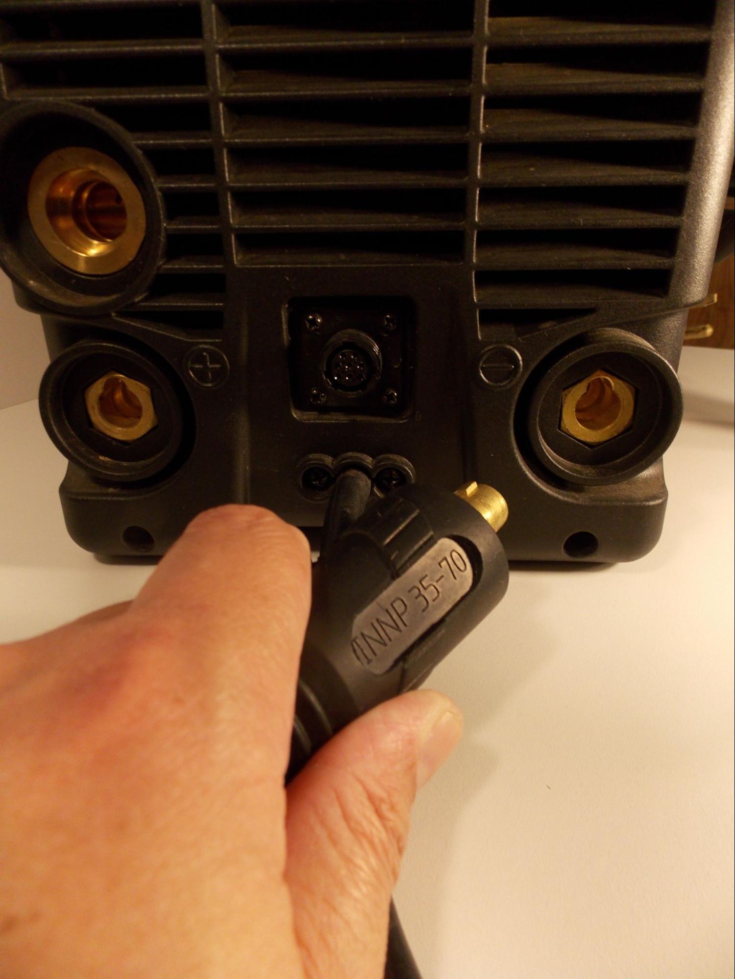
By changing which outlet our welding leads are connected to, we can change the way electricity flows through the system. In some cases, this can also be done with a switch or by changing a setting on the machine.
Direct Current
Direct current (DC) means that the flow of electricity is in one direction, all the time. This is very beneficial for the majority of welding that needs to be done, as most metals are welded using direct current. However, which direction the current is flowing has a big effect on the weld.
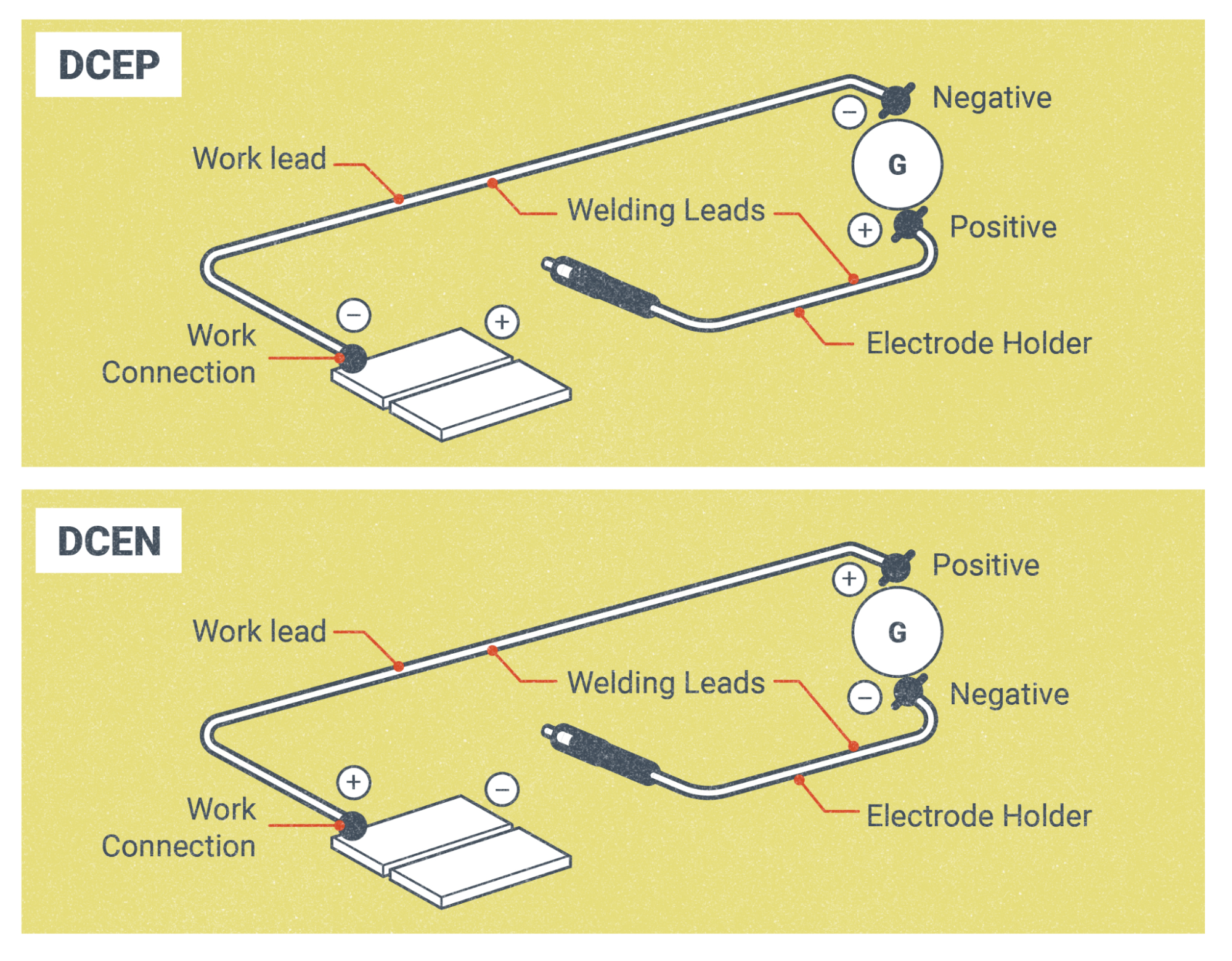
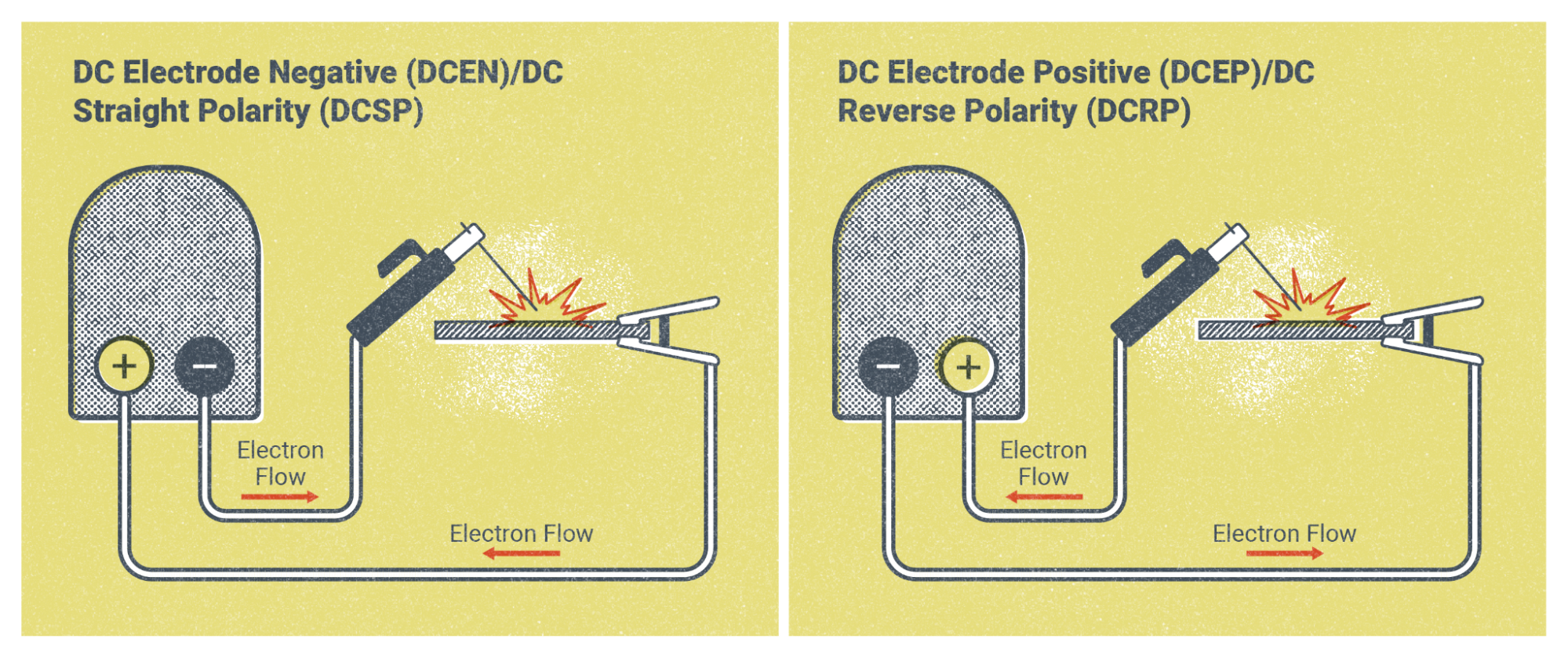
As stated earlier, we can think of a welding machine as having two poles, a positive and a negative pole. By changing which pole our workpiece lead and electrode lead are connected to, we can change the direction of the flow of electricity. This gives us two variations of direct current. We refer to them as direct current electrode positive (DCEP) and direct current electrode negative (DCEN).
DCEP means that the electrode lead is hooked up to the positive terminal on the welder and the workpiece lead is hooked up to the negative terminal. The majority of DC welding is done on DCEP. Processes like SMAW and FCAW use DCEP for most of their electrodes, and GMAW always runs on DCEP.
With DCEN, the welding leads are hooked up the opposite way, with the electrode lead being connected to the negative terminal and the workpiece lead being connected to the positive terminal. You will most likely encounter DCEN welding with GTAW and with certain self-shielded FCAW electrodes.
Direct Current Heat Distribution
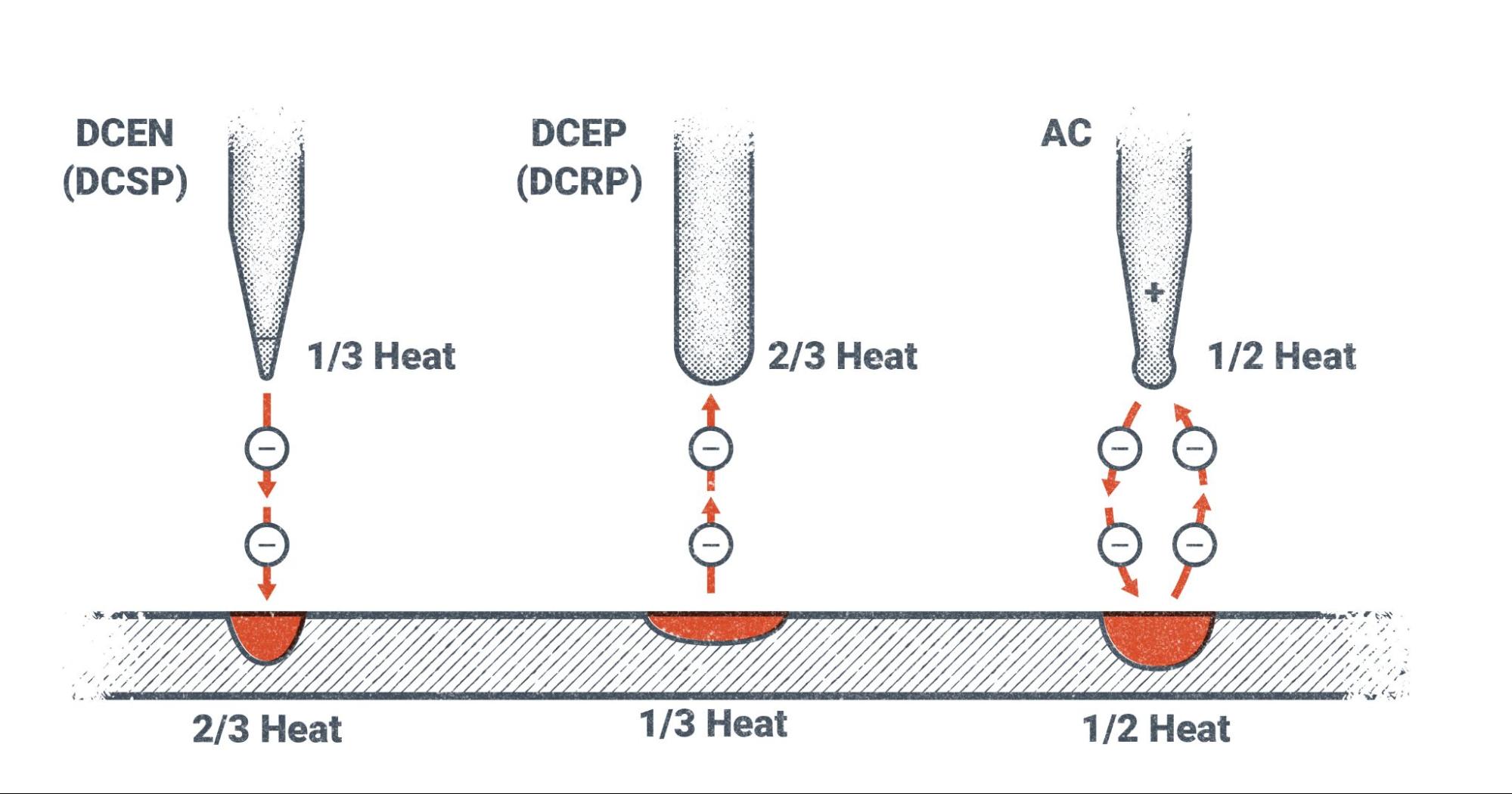
The main reason for using one polarity or the other between DCEP and DCEN is the heat distribution characteristics of each. In a welding system, electricity always flows from the negative pole to the positive pole. So at the point where the arc is created, the negative pole is emitting electrons across the arc and the positive pole is collecting them. As the heat is created by the arc, only one-third of it is concentrated on the negative pole while two-thirds of the heat is concentrated on the positive pole.
For example, with DCEP the electricity is actually flowing from the work lead to the base metal and then jumping across the arc to the electrode and then continuing back through the electrode lead to complete the circuit. This puts two-thirds of the heat on the electrode and one-third of the heat on the base metal. This is desirable for SMAW, GMAW, and FCAW processes because they have consumable electrodes, meaning that the electrode is melted and becomes part of the weld. We need the majority of the heat on the electrode because we actually need it to melt faster than the base metal during welding.
On the other hand, with a process like GTAW there are non-consumable tungsten electrodes. We don’t want this electrode to melt and become part of the weld, so we use DCEN. Since the electrode is connected to the negative pole, only one-third of the heat is directed to the electrode with the other two-thirds is going to the base metal.
Old Terms vs New Terms
As a note, you may still hear DCEP referred to by its older name, direct current reverse polarity (DCRP) and, likewise, DCEN as direct current straight polarity (DCSP). The former terms for these polarities had to do with the direction the electricity was flowing. Since the electricity was actually flowing from the work to the electrode with DCEP, it was referred to as “reverse polarity.” DCEN was “straight polarity” since the electricity was flowing from the electrode to the work. If you’re on a job where people keep using their former names, an easy way to remember which is which is that DCEN and DCSP (which are the same thing) are represented by the minus sign (-), which is a straight line and therefore refers to straight polarity.
Alternating Current
Alternating current (AC) is an electric current that is constantly changing polarity. This is the type of electric current that you have in your house, and most electronics plug into outlets that run on AC.
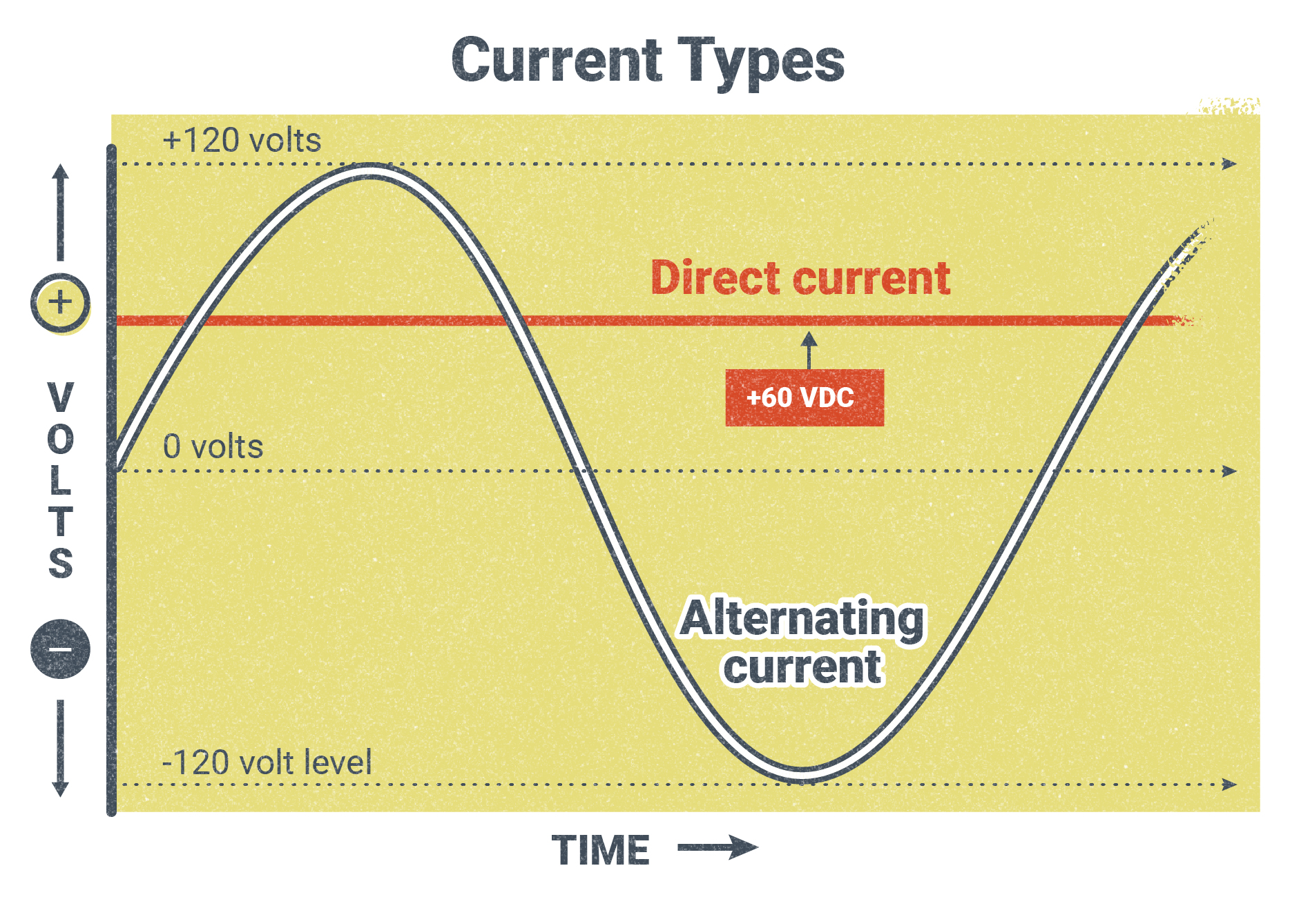
Figure 5.12 is a visual representation of AC. Above the 0V line is positive polarity and below it is negative polarity. The x-axis represents time. Notice how the AC changes from positive to negative over time. AC makes this change many times per second. The time it takes for one whole cycle is measured as a unit called a hertz. In North America, the electricity that goes to your house runs at 60 Hz, or 60 cycles per second.
What this would look like in welding is that the current flowing through the welding leads would be changing direction 120 times per second, to make 60 cycles per second.
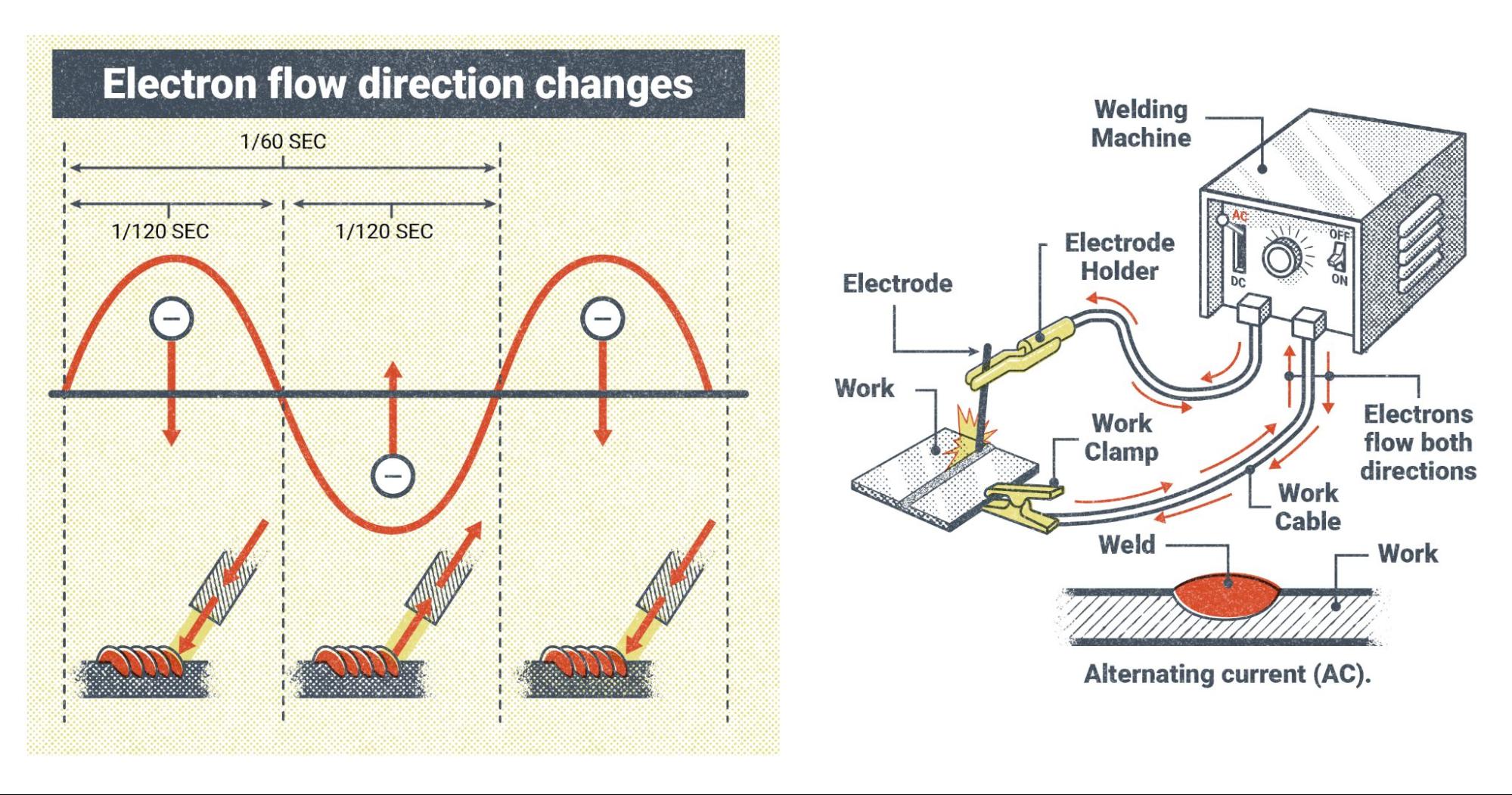
There are several reasons why welders might choose to use AC. It gives a heat distribution that is about 50/50 on the work and the electrode. The weld penetration to weld buildup ratio is also about 50/50. AC is easier to produce than DC, so machines that use AC only tend to be cheaper. With processes like GTAW welding, some metals can only be welded using AC, and with SMAW some welding rods are only designed to run on AC. It also helps eliminate the welding phenomenon called “arc blow,” which causes the arc to wander off course and can cause weld defects.
Some modern welding machines can change the number of hertz that AC cycles at, from as low as 20 Hz to over 200 Hz. Also, many machines that can produce AC can change the wave pattern, from the sine wave shown in Figure 5.12 to what is called square wave, which is much more efficient for welding (other waveforms are discussed in Chapter 11).
Types of Welding Power
There are two types of welding power (which is not to be confused with polarity). : constant current (CC) and constant voltage (CV). It is important to remember the difference, as they are used for different welding processes.
Before we review CC and CV, let’s cover some of the different welding processes.
Welding Processes
Up to now, this textbook has only mentioned the welding processes when referring to certain welding variables that are related to them. Before going any further, it will be helpful to have a basic understanding of the four main processes and how they work. Each of these processes has its own chapter that gives an in-depth explanation of its components and theory of operation. What follows is simply a brief overview to serve as a frame of reference.
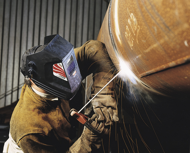
SMAW
Shielded metal arc welding (SMAW), also called stick welding, is the simplest welding process in terms of equipment and theory, and is usually the first welding process taught in schools and apprenticeships. The main components of the system are a welding power source, welding leads (cables that transfer the electricity to the weld), a work clamp and an electrode holder, and coated metal electrodes to make the weld.
The welding power source sends power through the work lead, which is attached to the base metal with the work clamp, and an electrode lead attached to the electrode holder. The electrode holder grips the coated metal electrode, which is a metal rod covered in a mineral substance called flux. The arc is struck between the rod and the base metal and as the weld progresses the metal rod is melted to become part of the weld and the flux is burned and consumed. Parts of the flux melt and coat the newly formed weld in a material called slag. Other elements burn off, creating a shielding gas cloud that surrounds the weld zone during welding. Both the slag and the shielding gas are intended to protect the weld from the atmosphere, because molten metal reacts badly with elements in the normal atmosphere.
SMAW is known for its simplicity and its ability to weld almost any metal, if the right type of welding rod is used. However, it does require a slightly higher level of manual skill than some other welding processes, such as GMAW welding.
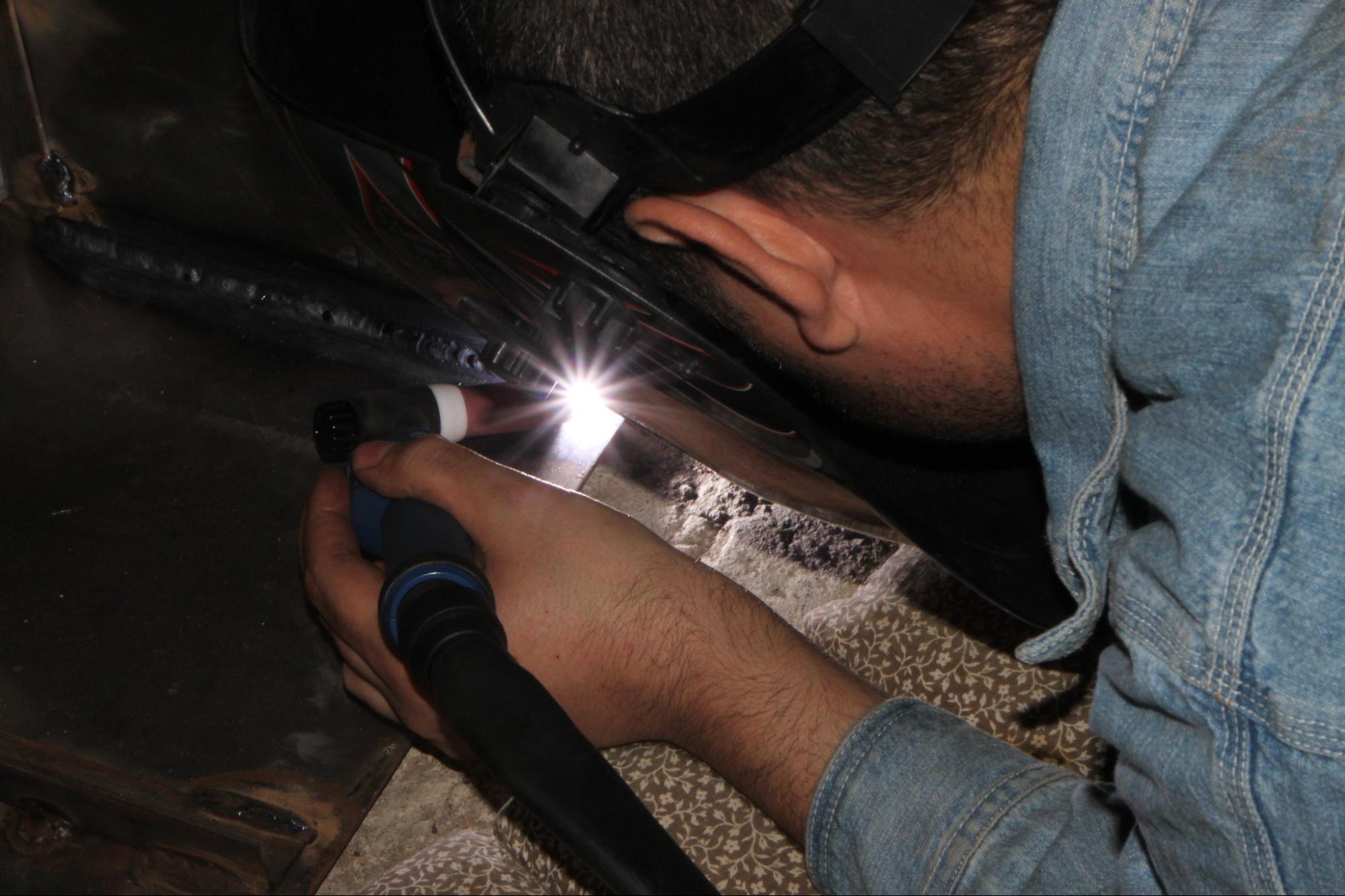
GTAW
Gas tungsten arc welding (GTAW) was originally known as tungsten inert gas (TIG) welding, and many welders still refer to it as TIG welding today. The electrode lead for GTAW welding is more than just a power cable. Rather than a simple electrode holder, GTAW uses a welding torch that allows for shielding gas and sometimes cooling water to pass through, as well as the welding current. The torch holds a tungsten electrode, from which the arc is emitted. This electrode is not consumed, as with SMAW, but only serves to conduct the electricity for the arc. A secondary filler metal, in the form of a bare metal rod, is added by hand to the weld pool as the arc travels along the base metal. Instead of having flux to create slag or shielding gas, a separate bottled shielding gas is used. This shielding gas is usually an inert gas, such as argon or helium, and is passed through the torch to the weld zone.
GTAW welding setups can be very simple, however modern GTAW welding power sources tend to be the most complicated when it comes to the welding settings. Additionally, the majority of GTAW welding machines nowadays use a foot pedal or thumb control to adjust amperage in real time during welding. Similarly, in many cases a water cooler or water chiller unit is added to help keep the welding torch cool, as it can easily overheat because of the slow welding speed of this process. Despite its slowness, GTAW welding is very desirable for its precision and cleanliness, as well as its ability to weld a wide variety of metals.
Helium: A Nonrenewable Resource
As a note on the gas used in GTAW, helium is a gas found in the earth’s crust. Its atoms are so small that they can pass between the atoms of any man-made container designed to hold it, thus allowing it to leak out. This is why your helium balloon goes flat after a few days. This property also allows for this gas to escape the gravitational pull of the earth and leave our atmosphere. This and our inability to artificially create helium means it is considered to be a nonrenewable resource. Although there is thought to be enough helium reserves for a number of years to come, usage is starting to be regulated and restricted (Helium, n.d.).
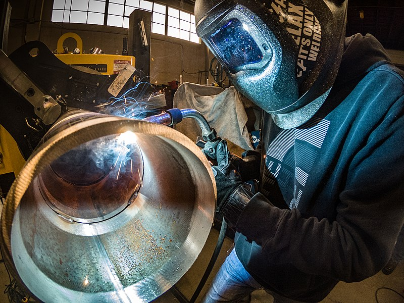
GMAW
Gas metal arc welding (GMAW) was at one time called metal inert gas (MIG) welding and most welders still refer to it this way today. You may also hear it called hard wire welding due to the solid metal wire electrode used in its wire-feed process. A bare wire electrode is fed from a spool through a welding gun into the weld. Some GMAW welding power sources have a built in wire-feeder unit, but in many cases the feeder unit is a separate component that must be attached to the power source. As the wire electrode is fed out of the gun, it is continually melted and becomes part of the weld. A bottled, external shielding gas is also fed through the gun to protect the weld so, like GTAW welding, there is no slag. The gas is usually carbon dioxide, or a mixture of argon and carbon dioxide.
Wire-feed processes like GMAW are more complicated in terms of the equipment required, but they are easier for new welders to learn. These processes also have the advantage of being able to make long welds quickly due to the spooled wire electrode. This is in contrast to SMAW and GTAW, which are much slower and the length of weld deposited at one time is limited by the length of the welding rod. The main drawback of GMAW welding is that there are a limited number of materials that can be welded with it, often because of the thickness of the material. Generally, GMAW is limited to thin materials like steel and aluminum. In the case of short circuit gas metal arc welding (GMAW-S, also called short circuit MIG or short-arc welding), it is not recommended for use on materials over one-quarter inch in thickness.
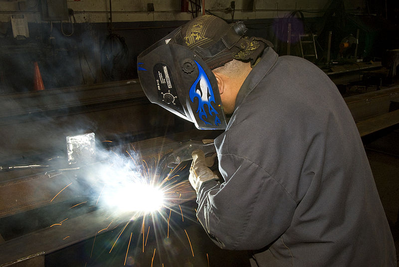
FCAW
Flux-cored arc welding (FCAW) is a wire-feed process similar to GMAW. In fact the same equipment used for GMAW can also be used for FCAW by changing a few parts in the welding gun and the wire feeder unit. The primary difference between the two processes is in the wire electrode. FCAW uses a tubular wire electrode that is filled with flux. Much like SMAW, the flux burns and creates slag and shielding gas to protect the weld.
There are two types of FCAW. One uses a bottled shielding gas in addition to the shielding from the flux. This is gas-shielded flux-cored arc welding (FCAW-G), which is also called dual-shield welding. The other type is called self-shielded flux-cored arc welding (FCAW-S), or inner-shield welding, and all protection for the weld comes from the flux alone. While FCAW is limited to welding ferrous metals (like steel, stainless steel, or cast iron), it is known for its speed and strength. Unlike GMAW, which is often limited to welding thinner materials, FCAW is able to weld materials of any thickness.
Constant Current
Now let’s return to the two types of welding power. CC is used for welding with SMAW and GTAW/TIG. They are both manual processes, meaning the welder controls almost everything by hand. As you recall from earlier in the chapter, both processes use their arc length to control the voltage applied to the arc. Lengthening the arc raises the voltage and shortening the arc lowers it.
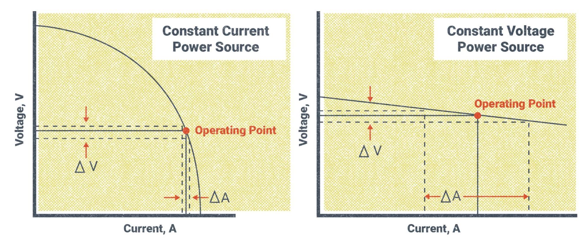
CC power gets its name from the fact that the welding machine always tries to maintain a constant wattage output. Remember that wattage is the total amount of electrical power and is composed of the total voltage and amperage. Looking back to our formula from earlier, we know that V × A = W. If the machine tries to keep a steady wattage output, this means that changes in voltage as a result of changing the arc length will also change the amperage. If the voltage increases the amperage will decrease, and vice versa, but the overall wattage will remain the same.
To illustrate this, say you set the amperage on the machine to 80A and then maintain an arc length that requires 24V. Using the formula V × A = W, we know that 24V × 80A = 1,920W. At that amperage setting, the welding machine will always try to maintain that 1,920W output. If the voltage were to increase to 30V, due to increasing the arc length, the amperage would automatically decrease to 64A, because 30V × 64A = 1,920W. Conversely, let’s say the voltage decreased to 20V due to holding a tighter arc length. We know that the amperage will instead increase to 96A, because 20V × 96A = 1,920W.
Hopefully, these examples give you an idea of what is taking place. They are not a completely accurate representation of the actual numbers because we do not want large fluctuations in amperage while welding. So in reality the total wattage will change a little. Figure 5.18 shows CC power on a graph, with the curved line representing the total wattage. You can see how changes in voltage affect changes in amperage.
Constant Voltage
CV power is used for all wire-feed welding processes. This includes GMAW/MIG and FCAW. These are known as semi-automatic processes. This means that the welder controls everything by hand, except for the feeding of the wire electrode, which is fed automatically by a wire-feed unit.
With these wire-feed processes, the main controls that welders can adjust on the welding machine are voltage and WFS. There is no amperage control; rather, the welding machine automatically adjusts the amperage to what is needed in order to fully melt the electrode as it is fed into the weld pool. So as you turn the WFS up, the welder automatically increases the amperage to melt the wire faster.
CV power gets its name from the fact that the welding machine tries to maintain a constant voltage setting throughout the weld. Because the wire is fed automatically, the welder is no longer able to maintain the arc length by hand. Instead, the machine maintains a constant arc length by maintaining one voltage. So, in a sense, when you set your voltage on the machine, you are actually setting the arc length. More voltage means a longer arc and less voltage means a shorter one. Along with the change in arc length, there is a change in how wide the cone of the arc is at the weld pool.

Because the welder still controls the movement of the welding gun/torch by hand, there will no doubt be fluctuations in how far or close they hold the gun/torch to the weld pool. Even an experienced welder cannot help this. CV power is able to accommodate this by maintaining a constant voltage and arc length and automatically adjusting the amperage. The closer the welding gun is held to the weld pool, the more amperage is required to melt the wire electrode. Figure 5.20 gives a visual representation of what is happening with the voltage and amperage when using CV power.
It should be noted that although it is said that the machine maintains a constant voltage, this is not entirely accurate, as there are always small variations. This is because no set of welding circumstances or machines are ever truly perfect.

Also, it is important to remember that voltage and WFS need to be balanced with each other in order to make good welds. Each wire electrode has a set of suggested settings that help welders determine how to adjust their welding machines.
Attributions
- Figure 5.1: Atom Diagram by AG Caesar is released under CC BY-SA 4.0
- Figure 5.2: Periodic table large by DePiep is released under CC BY 3.0
- Figure 5.3: Simple-electric-circuit by MikeRun is released under CC BY-SA 4.0
- Figure 5.4: Effect of Arc Voltage On Bead Shape by Nicholas Malara, for WA Open ProfTech, © SBCTC, CC BY 4.0
- Figure 5.5: Effects Of Voltage On Arc Length by Nicholas Malara, for WA Open ProfTech, © SBCTC, CC BY 4.0
- Figure 5.6: Effects Of Amperage On Penetration by Nicholas Malara, for WA Open ProfTech, © SBCTC, CC BY 4.0
- Figure 5.7: Different Direct Current Polarities by Nicholas Malara, for WA Open ProfTech, © SBCTC, CC BY 4.0
- Figure 5.8: Which Polarity? by David Ridge, for WA Open ProfTech, © SBCTC, CC BY 4.0
- Figure 5.9: How Direct Current Works by Nicholas Malara, for WA Open ProfTech, © SBCTC, CC BY 4.0
- Figure 5.10: DCEN And DCEP Welding Machine Setup by Nicholas Malara, for WA Open ProfTech, © SBCTC, CC BY 4.0
- Figure 5.11: Heat Distribution For Each Polarity by Nicholas Malara, for WA Open ProfTech, © SBCTC, CC BY 4.0
- Figure 5.12: Alternating Current Sine Wave by Nicholas Malara, for WA Open ProfTech, © SBCTC, CC BY 4.0
- Figure 5.13: AC Welding Machine Setup by Nicholas Malara, for WA Open ProfTech, © SBCTC, CC BY 4.0
- Figure 5.14: SMAW by Mgschuler is released under CC BY 3.0
- Figure 5.15: TIG-Welding-GTAW__102400 by Emilian Robert Vicol is released under CC BY 2.0
- Figure 5.16: Migpipe by Weldscientist is released under CC BY-SA 4.0
- Figure 5.17: Welding the frames (2929458501) by Oregon Department of Transportation is released under CC BY 2.0
- Figure 5.18: Constant Current And Constant Voltage Electrical Characteristics by Nicholas Malara, for WA Open ProfTech, © SBCTC, CC BY 4.0
- Figure 5.19: Effects Of Voltage On Arc Length by Nicholas Malara, for WA Open ProfTech, © SBCTC, CC BY 4.0
- Figure 5.20: Effects Of Voltage On Arc Length by Nicholas Malara, for WA Open ProfTech, © SBCTC, CC BY 4.0
A conductor is any material that has enough excess electrons with weak bonds that allow the electrons to flow from one atom to another.
An insulator is a material that does not allow electricity to flow through it easily or at all.
Wire-feed speed is a measure of how fast the wire electrode is being fed out from the spool by the feed unit and is measured in inches per minute.
The workpiece lead is the cable that connects the welding machine to the work clamp.
The electrode lead is the cable that connects the welding machine to the electrode holder.
Direct current electrode positive is a type of direct current in which the workpiece/base metal is set as the negative pole from which the electrons are emitted. Also called direct current reverse polarity (DCRP).
Direct current electrode negative is a type of direct current in which the welding electrode is set as the negative pole from which the electrons are emitted. Also called direct current straight polarity (DCSP).
Constant current is a form of welding power in which the amperage is set on the welding machine and the voltage is controlled manually by manipulating the arc length. As voltage increases during welding, amperage will decrease, and vice versa. Constant current is used with manual welding processes like SMAW and GTAW.
Constant voltage is a form of welding welding power in which the voltage is set on the welding machine. The machine then tries to maintain a specific voltage and therefore a specific arc length during welding. The amperage is automatically adjusted by the welding machine based on the wire-feed speed and the distance of the welding gun to the workpiece. Constant voltage is used with semi-automatic welding processes like GMAW and FCAW.
Shielded metal arc welding is a manual welding process that uses covered metal electrodes both to produce the arc and act as filler metal. The flux coating on the electrodes decomposes in the arc and becomes shielding gas and slag to protect the weld.
Gas metal arc welding is a semi-automatic welding process that uses a solid wire electrode fed from a wire feeder through a welding gun. This process does not use flux and therefore requires an external shielding gas.
Metal inert gas welding is an obsolete name for gas metal arc welding, as this process no longer uses only inert gasses. However, many welders still use this name when referring to GMAW.
Flux cored arc welding is a semi-automatic welding process that uses a tubular wire electrode filled with flux that is fed from a wire feeder through a welding gun. Depending on the type of flux, this process may or may not require an external shielding gas.
A manual process is a welding process in which the welder manipulates all aspects of the weld by hand, including arc length, rod or torch angle, weave or oscillation pattern, and travel speed.
A welding process in which the welder manipulates all aspects of the weld by hand, except for the wire-feed speed which is controlled by the feed unit.

.jpg)