5.2 Welding Power Sources
David Ridge
Transformers
Transformers are one of the oldest types of arc welding power sources. A transformer is a device that changes the voltage and amperage of an electric current while keeping the wattage the same. The two basic types of transformers are step-up and step-down transformers. Step-up transformers increase voltage while decreasing amperage. Step-down transformers decrease voltage while increasing amperage.
Remember that because V × A = W, it is possible to adjust the voltage and amperage of an electric current proportionally to each other and still have the same wattage. For example, 240V × 15A = 3,600W. Using a step-down transformer we can change the voltage to 30V and the amperage to 120A, because 30V × 120A = 3,600W.
A welding transformer is a step-down transformer. Most welders plug into wall outlets that provide 110V/120V, 220V/240V, or 440V/480V power. Whichever of these is used, they are all far more voltage than is needed for welding. Most welding is done somewhere between 15V and 40V, and even 30V is considered high for most processes. In order to make the current usable for welding, a welding transformer steps down the voltage from the wall outlet and steps up the amperage.
There are different variations in how a transformer is made, but that is beyond the scope of this discussion. What you need to know is that a step-down transformer is composed of a metal core with coils of copper wire wound around it in two or more places. The metal core is made up of thin metal sheets that are laminated or glued together. The core is shaped like a square with one or more slots cut into it. On one side of the square a copper coil called the primary winding is wound through the slot. On the other side of the square is the coil called the secondary winding. Electricity enters through the primary winding, is transformed, and exits through the secondary winding. In a step-down transformer, the primary winding has more turns in the coil than the secondary winding.
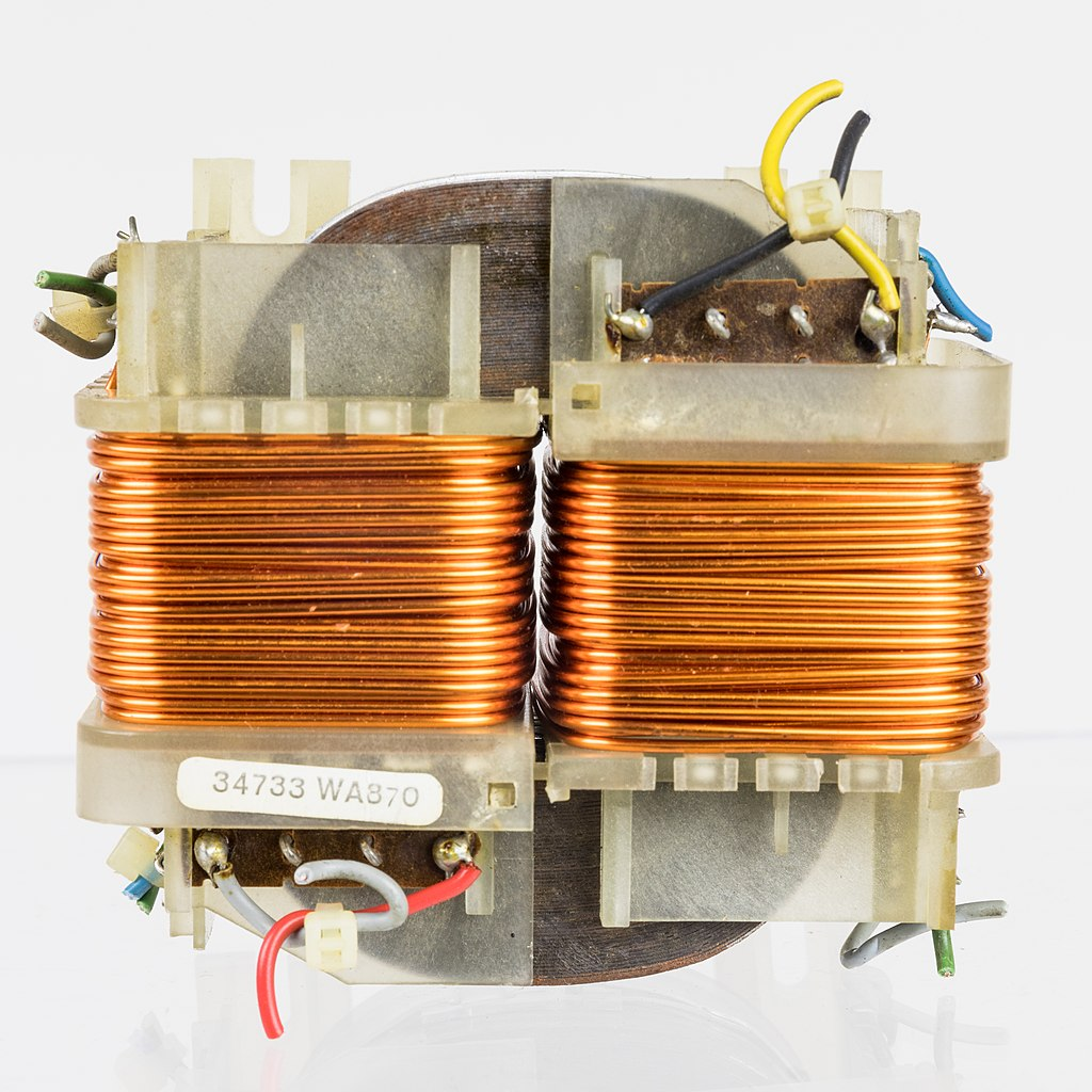
One issue that all transformers have is that they only work using AC. This is because of the constant change of polarity with AC. When the electrons in a conductor flow back and forth in an alternating current, it creates a phenomenon called magnetic flux. This magnetic flux can cause the electrons in another nearby conductor to start moving back and forth, creating another alternating current. The primary and secondary windings in a transformer are completely insulated from each other (meaning that they are neither touching nor electrically connected). The magnetic flux from the primary winding starts a new electric current in the secondary winding. In a step-step down transformer, because there are fewer turns in the secondary winding than in the primary winding, the new electric current has less voltage and more amperage but the same wattage.
DC does not create the same strong magnetic flux as AC, so a transformer cannot work using DC nor can it output DC. Yet many welding machines put out DC power. This is achieved through another device called a rectifier, which converts AC into DC for welding.
Transformers are still around today, although they are less common. This is because they tend to be larger, heavier, and less efficient than the newer inverter welders. However, transformer welders are known for being extremely reliable and generally having a higher power output than many inverters, as well as being somewhat cheaper to purchase.
Inverters
Another welding power source is inverters. Inverter welders are becoming the standard for many welding applications due to their portability, precision, and the plethora of advanced welder settings options that many come with. Inverter power sources use sophisticated electronics to convert the power from the wall outlet into welding power. Lacking a heavy metal core and copper windings, they are much smaller and lighter than transformers. They are also more efficient and highly adaptable. The majority of multi-process welders (welders that can be used for three or more processes) on the market today are inverters.
One of the primary draws of inverter welders is the variety of welder settings that many of the higher-quality units come with. They can easily change polarity or go from CC to CV power and have various settings and options to help fine-tune the welding arc. Digital displays and infinite adjustment knobs allow for welders to adjust the voltage by tenths of a volt for wire-feed processes. Hot start and arc force settings help start and maintain the arc for SMAW. GTAW welding inverters usually have the most options, with adjustable AC balance, frequency, wave patterns, pulse settings, crater fill timers, and so on. The point is that many modern welding machines have more bells and whistles than their older counterparts. This is not to say that older machines are useless—m are as good today as when they were first made. However, the progress of welding technology is exciting.
The main drawback of most inverters is the cost, as all of the technological advancements come with a hefty price tag. Though prices have evened out in recent years, and at the time you are reading this it may not be as much of an issue. The second disadvantage is the potential for the electronics inside of inverters to get damaged or wear out. Most welding environments are harsh, and even when treated with care, these machines sometimes fail. However, inverters continue to be a popular option for many welders and fabricators.
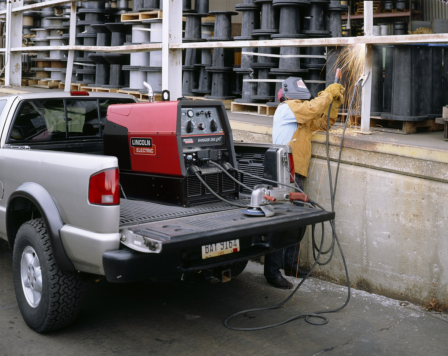
Mobile Power Sources
The limitation of most welding machines is that you need to be somewhere with electricity to use them. This usually means being in a shop with electrical outlets. However, many welders operate out in the field, away from such convenient access to power. This is possible thanks to mobile engine-driven power sources. These welding machines are powered by a combustion engine that drives an electric generator. Depending on the model, the engine can run on one of several fuels, including gasoline, diesel, or propane.
These welders are hardy machines that are meant to operate in harsh environments. They range in size and power from being small enough to wheel around by hand and outputting a few thousand watts to being 600 pounds or more and capable of putting out over 10,000W. As such, engine-driven power sources are a staple of pipeline welding and mobile repair operations.
Categories of Welding Power Sources
There are too many specific types of welders to discuss them all in depth. This section will attempt to break down welding machines into categories by size, power, and type. It is not always necessary to categorize welding machines (and the categories are very broad and general, like ours), but this will serve to help you understand some of the capabilities of different welders.
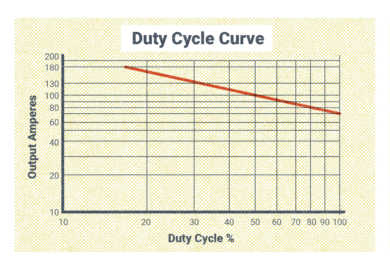
One aspect of a welder’s size and power is its duty cycle, which is a measure of a welding machine’s ability to operate continuously. The measurement is based on what percentage of time a welder can operate continuously at a certain amperage in a 10-minute period before the internal components overheat and need to cool down. For example, a welder with a 60% duty cycle at 150A can weld continuously for six out of 10 minutes at that amperage. If you were to weld continuously for longer than six minutes, the welder would automatically shut itself down until it was cool enough to resume welding.
Duty cycle is one of the most determinative factors in how much a welder costs. Even welders with many functions but a low-duty cycle will generally cost less than a welder with fewer functions but a significantly higher duty cycle. Welders with high-duty cycle ratings also tend to be more powerful.
Hobby/DIY Welders
The welding machines that are sometimes labeled “hobby” or “DIY” machines tend to be the smallest, cheapest, and least powerful welders on the market. Many of them run off of 110V/120V power (though a few use 220V) and they normally do not have a maximum amperage output greater than 100A-140A. These also tend to have a duty cycle of 20% to 30% or less and have limited special features. This usually only makes them suitable for small welding jobs on thin materials, such as auto body work or light fabrication. This doesn’t mean they are bad machines, though.
They are intended to appeal to people who want to work on small projects at home (hence “DIY”) or perhaps do light equipment maintenance. With a price tag of maybe a few hundred dollars, they are meant to be affordable and easy to operate (an example is the e TITANIUMMIG 140 Professional Welder with 120V Input found at Harbor Freight). If this is all that someone needs to do what they want, there is really no reason to have a more expensive machine.
Mid-grade Welding Machines
What we will term here as mid-grade welders is a category of welding machines designed for people who are more professionally affiliated with welding. This means they weld more frequently than the hobbyist or DIYer and on materials that require a more powerful welder, but it may not be their full-time job. Most of these welders require at least a 220V/240V power supply and have a maximum output of around 200A. Their duty cycle is usually between 40% and 60%, and you start to see more special features included.
An example of this kind of machine is the Millermatic 210. This level of welding machine is not so expensive that an individual couldn’t buy one for personal use, but they would have to be convinced that they needed a welder of this caliber. With the ability to weld steel up to around half an inch thick, these welders are good for equipment maintenance on farms, small mobile welding repair businesses, or for someone who may want to run a welding side job from their own shop.
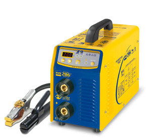
Industrial Welding Machines
Industrial welding machines are among the largest and most powerful welders (however, due to developing technology, the size of many of these machines has been greatly reduced without a subsequent loss of power). They are designed for professional welders, fabricators, and contractors. These machines need a minimum 220V/240V power supply, and many require 480V supplies. They have amperage outputs that can reach 300A-450A, and with 80% to 100% duty cycles, they can operate at welding amperage almost indefinitely. They have the capacity to weld materials of any thickness and are often equipped with a number of special functions and features to improve weld quality and versatility.
Aside from the massive power requirement, these machines are usually too expensive for individuals who aren’t engaged in welding full-time to want to own. Fabrication shops, manufacturing plants, shipyards, ironworkers, pipe welders, and other such entities employ these machines on a daily basis to earn a living and make the things that keep the world running.
Dedicated Welding Systems
So far we have discussed many different aspects of various welding machines and processes. However, welding systems can otherwise be broadly divided into two categories: dedicated welding systems and multi-process systems.
A dedicated welding system or welding machine is one designed to primarily perform one kind of welding or one process. This means that they are usually limited in their number of functions, but those they do have are designed specifically for their intended process. This often boils down to which type of welding power a machine can use. Machines that are only capable of running CC power can only be used for SMAW and GTAW while machines that run CV power can only be used for wire-feed processes. As you can see, there is some overlap, even when talking about dedicated machines. Any machine that can run SMAW can also run GTAW (though this is not always an effective way to run GTAW). Similarly, any machine that can run GMAW can also run FCAW.
For example, some machines are designed specifically to use only CC power. This limits them to processes like SMAW and GTAW. However, this kind of machine can also be specifically tailored with functions that support one of those processes over the other, even though it can technically perform both. The same can be said for CV machines. One CV welder can be specifically equipped to perform GMAW welding while another can be geared more for FCAW. But each machine is still technically able to perform both.
Another way a welding machine can be intentionally limited to a certain type of welding is through the polarity selection. Some machines can only output DC and others may only output AC. The purpose of a dedicated welding machine is mainly to reduce its cost. The more functions a welder has, the higher its price.
Multi-process Machines
Multi-process machines are welding power sources that can support three or more welding processes. This type of welder is increasingly more popular these days. Many (though not all) multi-process machines have the ability to switch between CC or CV power as well as put out both AC and DC for welding. This allows them to perform all four of the main welding processes (SMAW, GTAW, GMAW, and FCAW). The main drawback of these welders, aside from the high price, is that they often require a number of additional components in order to switch between processes.
Both multi-process and dedicated welding machines can come in any size and/or power output category.
Safety Considerations
Before we finish this chapter, it would be worth mentioning some safety considerations based on the material we’ve covered so far.
Now that we know a little bit about welding power, hopefully it is obvious that it involves large amounts of electric current. The interaction of voltage and amperage can be complex, and many factors can affect the potential danger of an electric shock. Both voltage and amperage can be dangerous, but amperage is the more dangerous factor in this case. In general, it is assumed that a current with less than 50V is not seriously harmful, though it can cause discomfort (Post, 2023). Most welding takes place using between 20V and 40V when the arc is on. In contrast, even a current as low as 0.1A to 0.2A can be lethal when driven with enough voltage. To put it in perspective, welders often work with currents reaching into the hundreds of amps (Peshin, 2017).
That being said, the utmost care has gone into designing numerous safety mechanisms for welding machines and their related accessories. Welders perform their work every day, and the number of incidents is very small considering the number of welders currently working and the environments they find themselves in (Dekker, 2021). Still, as the welder, you should take every necessary precaution when working with electricity. You must never put yourself in a position where you could become part of a live electrical circuit. This means understanding how your welder machine works, knowing which components are electrically “hot” when the machine is on, and keeping an eye out for damage to parts in the system.
It was mentioned earlier in the chapter that resistance and heat were a factor in the breakdown of certain components. This is relevant when considering the duty cycle of a machine. You should never exceed the duty cycle of any welder. Recall that duty cycle is essentially how long it takes a welder to overheat under continuous use. Reaching overheating can cause damage to the internal components of the welder, and every time it overheats the internal insulation that keeps it cool is degraded, thus destroying the safety mechanism provided by the duty cycle. If overheating happens frequently, the welder will begin to overheat sooner, and constant overheating can cause damage to the machine, making it less safe to operate. This means that if the duty cycle is 60% (or six out of 10 minutes), you should not weld right up to the six-minute mark when the machine would shut itself off. Rather, you ought to pause your welding every few minutes to let it cool down.
Also mentioned earlier was how excess heat in the welding system can be a sign of worn or damaged parts or connections. Adequately maintaining welding equipment is important for both safety and making good welds. Parts such as leads, work clamps, electrode holders, welding guns, and connectors are some of the components most susceptible to wear and damage and often overheat as a result. A component that is overheating should be replaced or repaired as soon as possible, even if the system is still functioning correctly, because the overheating will only worsen over time. This could cause more serious damage to the welding system as well as put you or others in danger of burns and electrocution.
Another electrical hazard to be aware of is a “short circuit.” A short circuit is when flowing electricity somehow finds another path to complete its circuit. Usually this alternate path is undesirable and takes a shorter route toward completing the circuit, hence its name. An example of this can be the electrical cord that powers a light: If a break in the insulation kept the hot and neutral wires apart, the electricity would start flowing back through the circuit where the wires touch before reaching the light.
A short circuit is often caused by damage to electrical cables or components, which can happen in any number of ways. A cable can be severed, a foreign object can come in contact with electrical components, the circuit can be overloaded with a current it is not rated for, etc. However it may happen, there are two possible outcomes. The most common is that a short circuit causes a bright flash of light, a shower of sparks, and a loud popping sound. This concentrated explosion can be alarming but is usually only momentary, as this outcome will trip the circuit breaker attached to the circuit as a safety mechanism. The other possibility is that the electricity will keep flowing through the new, alternate path for an extended period of time. This is very dangerous, as anyone who comes in contact with the new electrical path could be electrocuted. Also, whatever object the electricity is flowing through will start to heat up. This is often how electrical fires start.
To prevent short circuits, it is important to maintain electrical equipment properly, avoid situations where metal objects can come in contact with the circuit, keep electrical equipment away from water, make sure all equipment is rated for the amount of power in the circuit, and make sure circuit breakers are of an appropriate size and in good working order.
One effective way to keep welding machines in good working condition is to have them serviced and calibrated by a certified manufacturer’s representative or other qualified technician. This should be done at least annually, but in many production shops, this may be done every three to six months. Welding shops that are certified under certain codes or standards are often required to have routine service for certification (you will learn more about codes and standards in Chapter 17). Regardless of whether the equipment you use is regularly serviced, it is a good practice to check your machine over every day before starting work.
A welding environment has many warning labels and built-in safeguards and safety mechanisms. And as a welder you will no doubt be trained in safety regulations and practices. However, it is important to remember that the best and most effective safety mechanism is your own ability to think and be aware of your surroundings. No amount of warnings, safeguards, or safety regulations will keep you as safe as simply paying attention to what’s going on around you and having good common sense when approaching any situation.
Attributions
- Figure 5.21: Philips N4422 – power supply transformer-2098 by Raimond Spekking is released under CC BY-SA 4.0
- Figure 5.22: U.S. Army Corps of Engineers Buffalo District Commander by U.S. Army in the Public Domain; United States government work
- Figure 5.23: GYS – MMA Arc Welder main by Bruno Bouygues is released under CC BY-SA 3.0
- Figure 5.24: SMAW Field Shot by Mgschuler is released under CC BY 3.0
- Figure 5.25: Effects Of Voltage On Arc Length by Nicholas Malara, for WA Open ProfTech, © SBCTC, CC BY 4.0
Duty Cycle is a measure of how robust a welding machine is, and is determined by what percentage of time a welder can operate at a certain amperage in a ten minute period.
