6.1 Common Hand Tools
David Ridge
After their welder, a toolbox filled with hand tools may very well be the next most important thing in a fabricator‘s arsenal. Knowing how to use hand tools to fit and fabricate metal structures requires time and practice but is an essential skill for anyone who wants to succeed in this industry.
Fabrication vs Welding
Fabrication is the process of making something, especially a metal product, from stock or pre-cut material. On any given job, a fabricator can be involved in measuring, cutting, and shaping material, fitting and assembling parts, welding, and finishing operations such as grinding/sanding or machining. This list is not extensive and there may be other operations that are needed during production that a fabricator might be involved in. Note that not all welders are fabricators. For example, a welder whose only responsibility is to weld out assembled parts would not be considered a fabricator.
The tools discussed in this section represent a large portion of what you might find in a welder’s personal toolbox. Not every tool out on the market is discussed, but there is enough depth of information included to give you a good idea of what you might need to start fabricating. Some specialty items that a welder may or may not need, or that they may not own personally but would find in a weld shop, are also covered.
Layout Tools
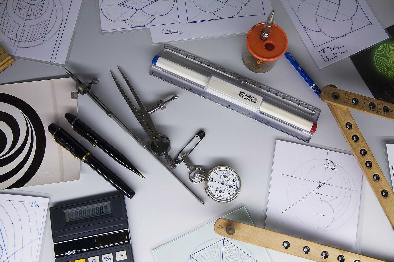
When you hear the term layout used in a welding shop, the context is usually about taking measurements and/or marking locations. Layout can be a complex process. A fabricator must have a decent amount of skill in reading blueprints, applying shop math, and using measuring tools, as well as a good general grasp of how a metal weldment goes together.
Most layout tools will fall under the categories of measuring and marking tools, but there are some others to consider.
Measuring Tools
Measuring tools are a broad category, and for anyone who builds things by hand, they are indispensable. Tools exist for determining any dimension: to find an object’s length, width, depth, height, and thickness; determine if something is square (90-degrees with itself), angled, or curved; and confirm if an object is level (perfectly horizontal) and plumb (perfectly vertical). Depending on the work you are doing, any or all of these dimensions may need to be taken into account.
Some measuring tools are very precise, such as a micrometer, while others give a less accurate measuring scale, like a metal ruler. You want to use the correct measuring tool for the work you are performing. Sometimes a less precise tool will work just fine if the tolerances you are working with are somewhat loose.
Let’s review some measuring tools you may encounter on the job. It is worth mentioning that many of the tools covered have a modern digital version. They are more expensive but allow for greater precision in that it is easier to read the tool.
Tools for Linear Measurement
Linear measurement is measurement taken in a straight line. Length, width, and material thickness (which can be considered depth or height) are linear measurements that welders and fabricators often need to find. The most common tools for taking linear measurements are tape measures and rulers.
If you do any amount of fabricating as part of your job, you need a tape measure. Tape measures come in a number of different sizes, lengths, and scales. They can be cheap or expensive, plastic or metal, basic with no frills or have special features. The kind of tape measure you will need depends on what you are measuring.
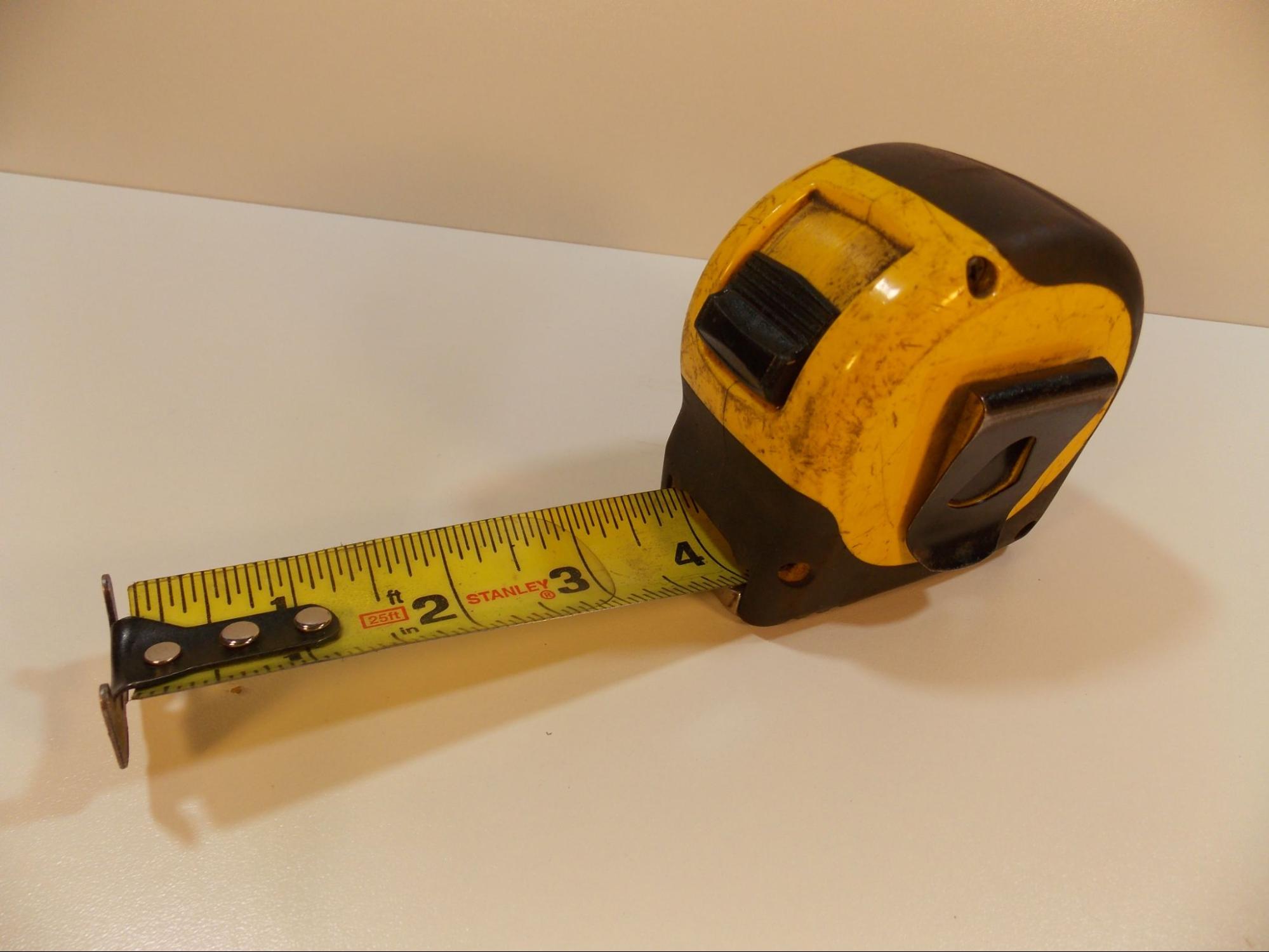
The scale on a standard tape measure is accurate enough for most of the measuring a fabricator does on a daily basis. Most tapes only have one scale—either imperial scale (inches and feet) or metric scale (millimeters and centimeters)—but there are some that have both, with one on each edge of the tape. Be certain that you understand the scale you are working with.
Reading a tape measure scale can take some practice. The majority of tapes used in fabrication and construction break the scale into one-sixteenths of an inch or 1-millimeter increments. Other incremental marks include quarter-inch, half-inch, inch, and foot marks for the imperial scale and centimeter and meter marks for metric. Assume the scale might be differ from one tape to another. Some may have fine increments while others, usually very long tapes, might only show the quarter-inch or centimeter marks.

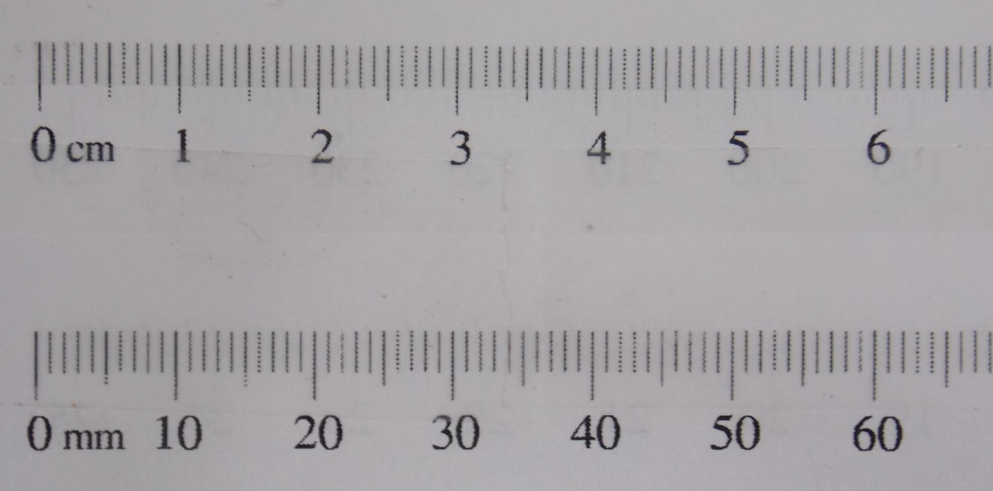
Increment Notation
When you see measurements written on blueprints or on parts, you may see them followed by “ or ‘ marks, or by m, cm, or mm. When working with the imperial scale, the “ mark means inches and the ‘ means feet. For example, 7’ 8” means seven feet, eight inches. In the case of fractional numbers, a number written ⅝” means five-eighths of an inch. When using the metric scale, an m following a dimension indicates meters, cm indicates centimeters, and mm is millimeters. For example, 5 m is five meters, 7 cm is seven centimeters, and 3 mm is three millimeters.
Tape measures come in a number of lengths, ranging from two feet to 100 feet or more. The most common lengths for fabrication and construction work will usually be between 25 and 40 feet. Metric tapes can be found in similar lengths, such as from one to 50 meters or more. Also, be aware that the width of the tape blade can vary by design. The wider the blade, the stiffer it will be, which will allow you to extend the tae further without assistance and also ensure it is straight so you can take an accurate measurement.
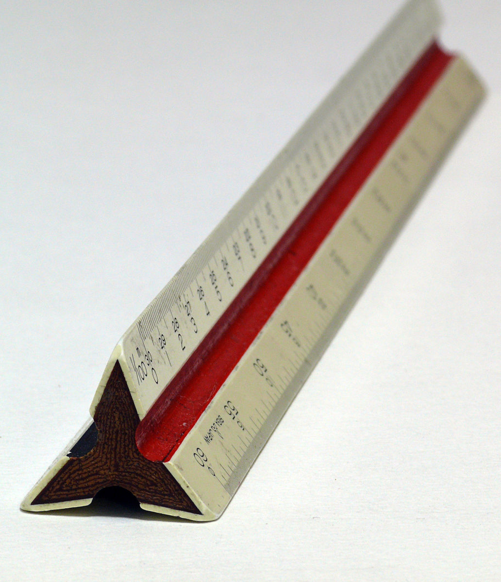
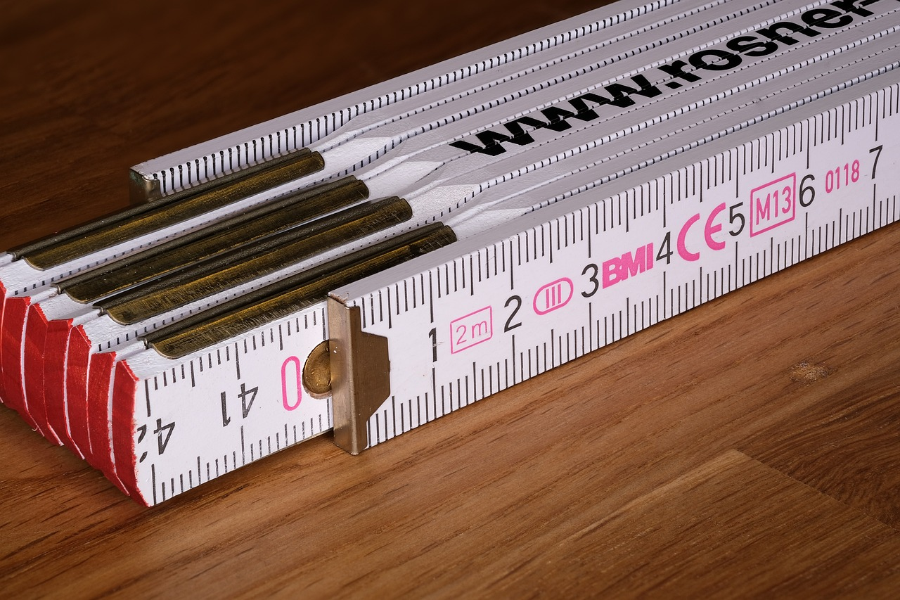
As you probably know, a ruler works much like a tape measure except it is shorter. The benefit of a ruler over a tape measure in certain circumstances is that you can use a ruler as a straight edge to mark straight lines or to check if something is true (i.e., perfectly straight). Rulers also come in a variety of lengths, widths, and measurement scales. While most of us are familiar with the plastic rulers used in grade school, there are many different types of rulers. Ones used for fabrication can be very long, sometimes 8–10 feet (2.5–3 m). There are also rulers that fold or extend. Often you will find a ruler as a part of another tool, such as one of the various types of squares, or a protractor. Rulers that are two feet (60 cm) or less tend to have finer measurement scales than tape measures, often down to thirty-seconds or even sixty-fourths of an inch, though they don’t usually get smaller than millimeters for the metric scale. Some rulers will have different scales on either side or even each edge.
Some other measuring tools that deserve mention are calipers, micrometers, and feeler gauges. These three are sometimes referred to as precision measuring tools. They are used to take very fine measurements. When using these tools, you are no longer working in fractions but in tenths, hundredths, and thousandths of an inch or hundredths of a millimeter. Not all welders work with such small measurements, so you may not see or use these tools often.
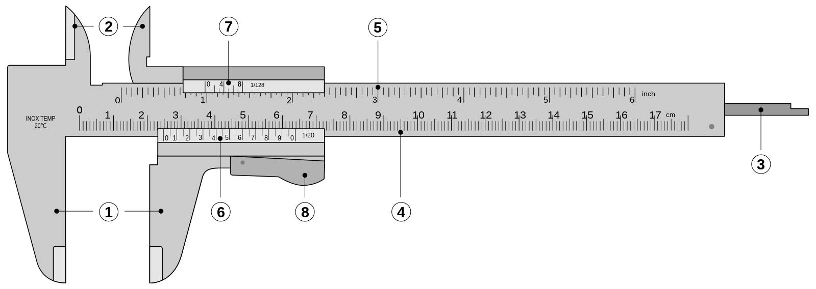
Calipers can be used to take measurements in a number of different ways. Their most common use is to find the inside and outside dimensions of something round, such as the inside diameter of a pipe or the outside diameter of a bolt. The tool accomplishes this through the use of two sets of jaws, one for inside and one for outside dimensions. Calipers can also be used to find the depth of something, like a hole or a notch through the use of a depth probe. Calipers are pretty much confined to use for taking small dimensional measurements, as the scale on most calipers is not more than 6–8 inches (15 cm to 20 cm) long. They can be used to take accurate measurements in thousandths of an inch.
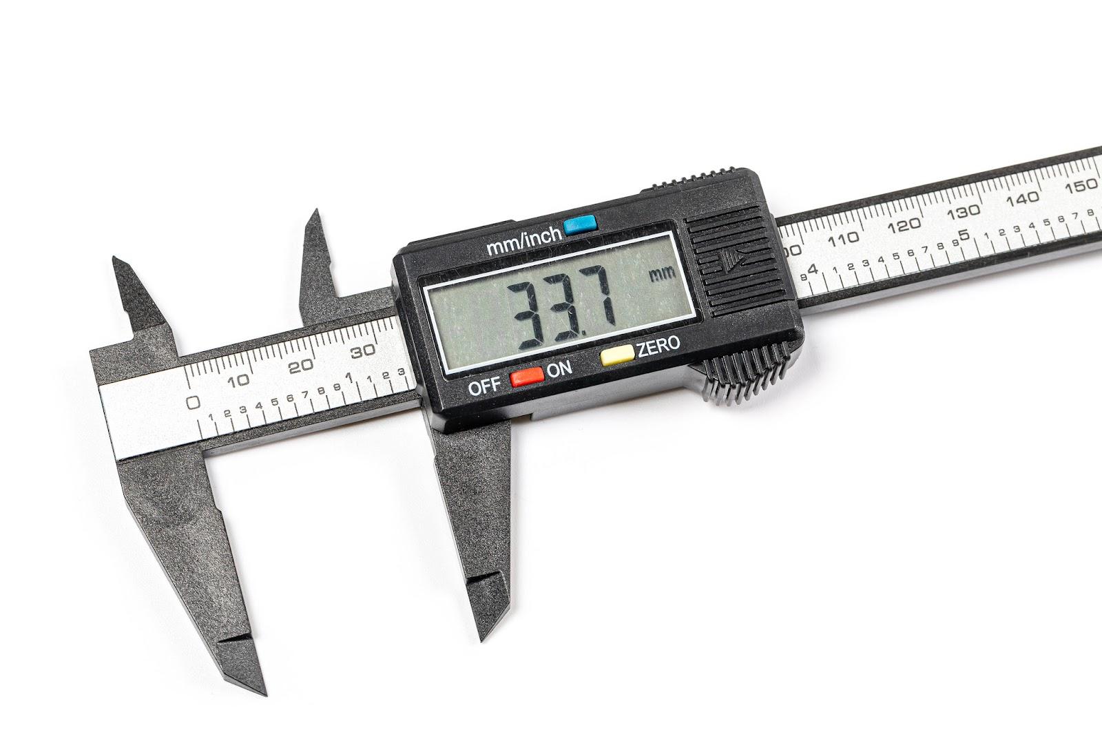
There are three types of calipers: vernier, dial, and digital. The main difference between these is in how the scale is read. The scale on a vernier caliper looks like a ruler with fine increments. The scale is read by sliding the lower jaws up or down the bar and aligning small hash marks on the shuttle portion with the marks on the ruler. Vernier calipers get their name from the special set of incremental hash marks on the shuttle, which are called a vernier scale. As the name suggests, dial calipers use a dial indicator to show a measurement. As the jaws slide up or down the bar, the needle in the dial indicator winds around to indicate the dimension. Digital calipers have simply replaced the vernier scale and the dial indicator with a digital display, making it easier to read.
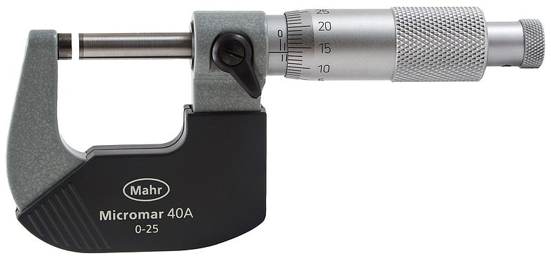
A micrometer is another tool used to take small measurements in thousandths of an inch or hundredths of a millimeter. Micrometers look like a small C-clamp with a twistable dial on the end. Micrometers are often used to precisely determine the thickness of a piece of material. The lower bar, called the spindle, moves in or out as the dial is twisted. The scale on the dial—usually a vernier scale—gives the dimension between the spindle and the anvil (the small cylinder at the top) in thousandths of an inch or hundredths of a millimeter. Most micrometers come in increments of an inch or 25 millimeters.
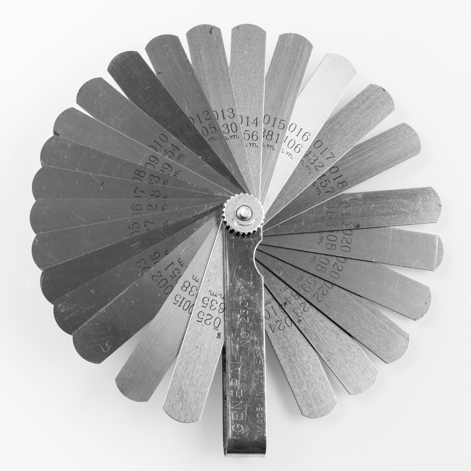
The final measuring tool we’ll review is a feeler gauge, which is used to find the dimension of an empty space. A feeler gauge is made up of many thin metal strips measuring from about 0.035 inch at the thickest down to about 0.001 inch at the thinnest, or about 0.889 mm to 0.051 mm. You can find the dimension of a space between two parts by sliding the feeler gauge’s strips into the gap. In order to find the dimension of a gap larger than the thickness of any one of the strips, you can stack strips together and add their total thickness to get an accurate measurement.
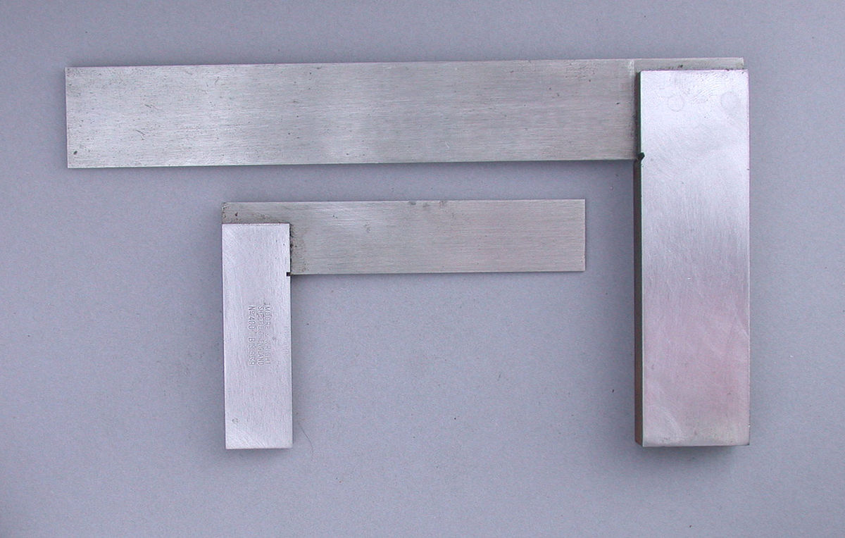
Tools for Finding Square
When you hear the term square applied to something, it means that it has at least two edges that are exactly 90-degrees to each other.

The squareness of a part or of a whole weldment is often one of the most important dimensions to account for when building almost anything. Sometimes you will need to find square in order to mark a location or cut the end of a part. There are many different tools that can be used to do this, and the reason for such a wide variety is the many different stock material shapes used to build things. Metal stock, in particular, comes in a wide range of shapes and sizes, often requiring several tools to accommodate these variances.
The most common tools for finding square are actually called squares. Their size, shape, and additional features are all based on the different materials that need to be measured. However, they all have the same basic function of finding 90-degrees with their perpendicular legs. For this reason, they are somewhat interchangeable in many situations. They include:
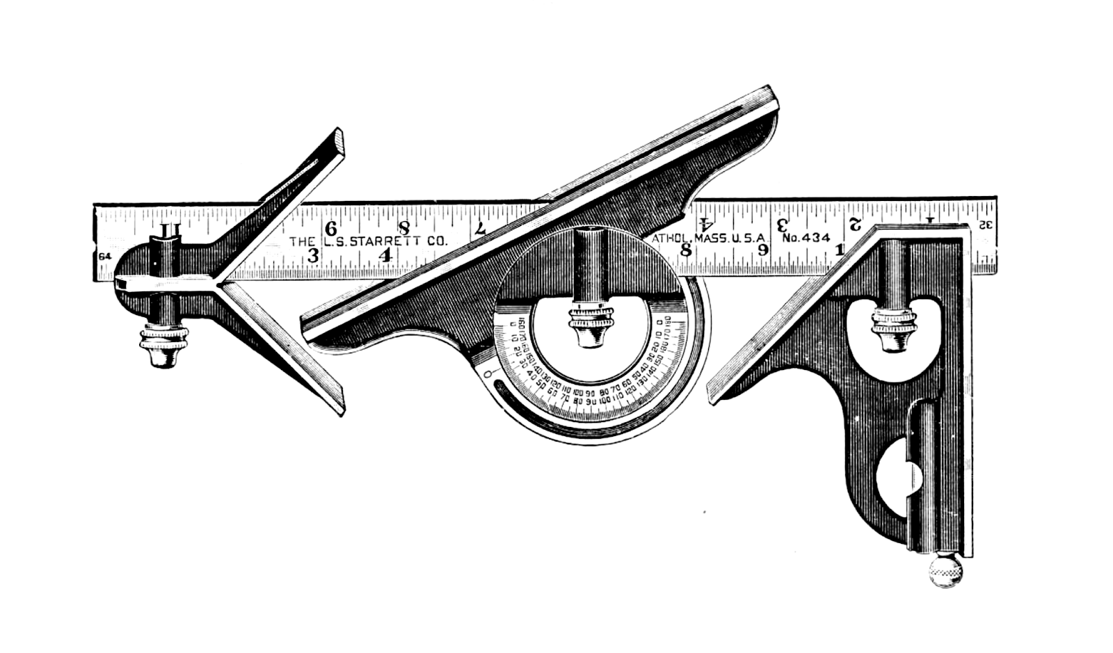
- Combination (combo) square
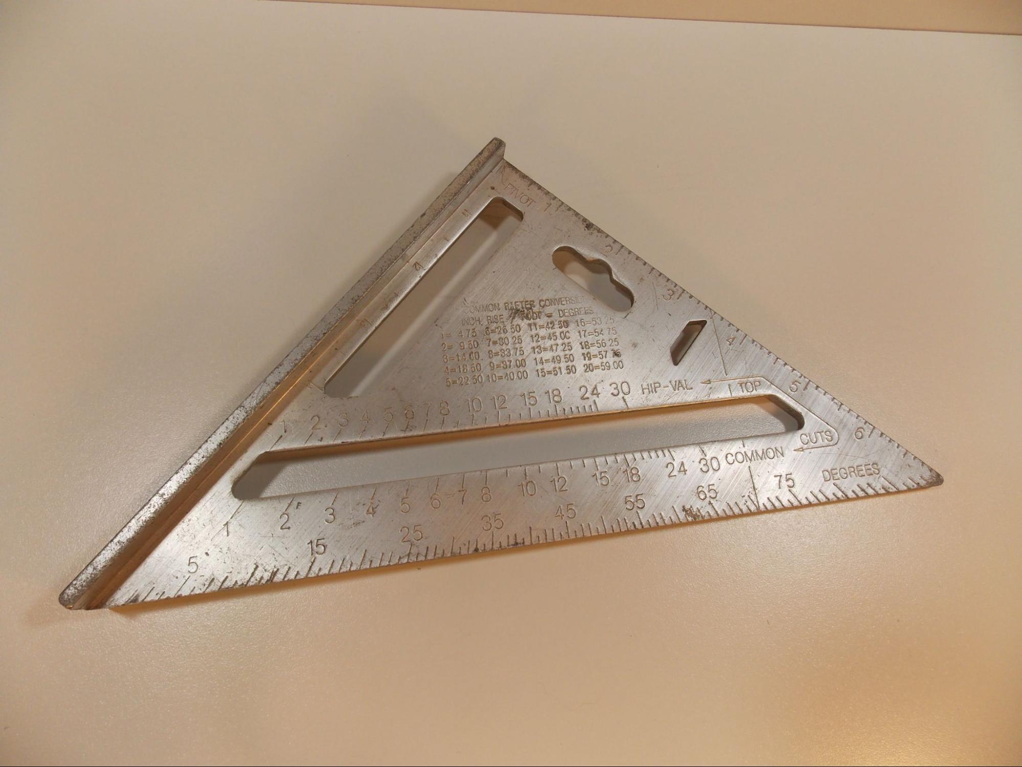
- Rafter square (slso known as speed square)
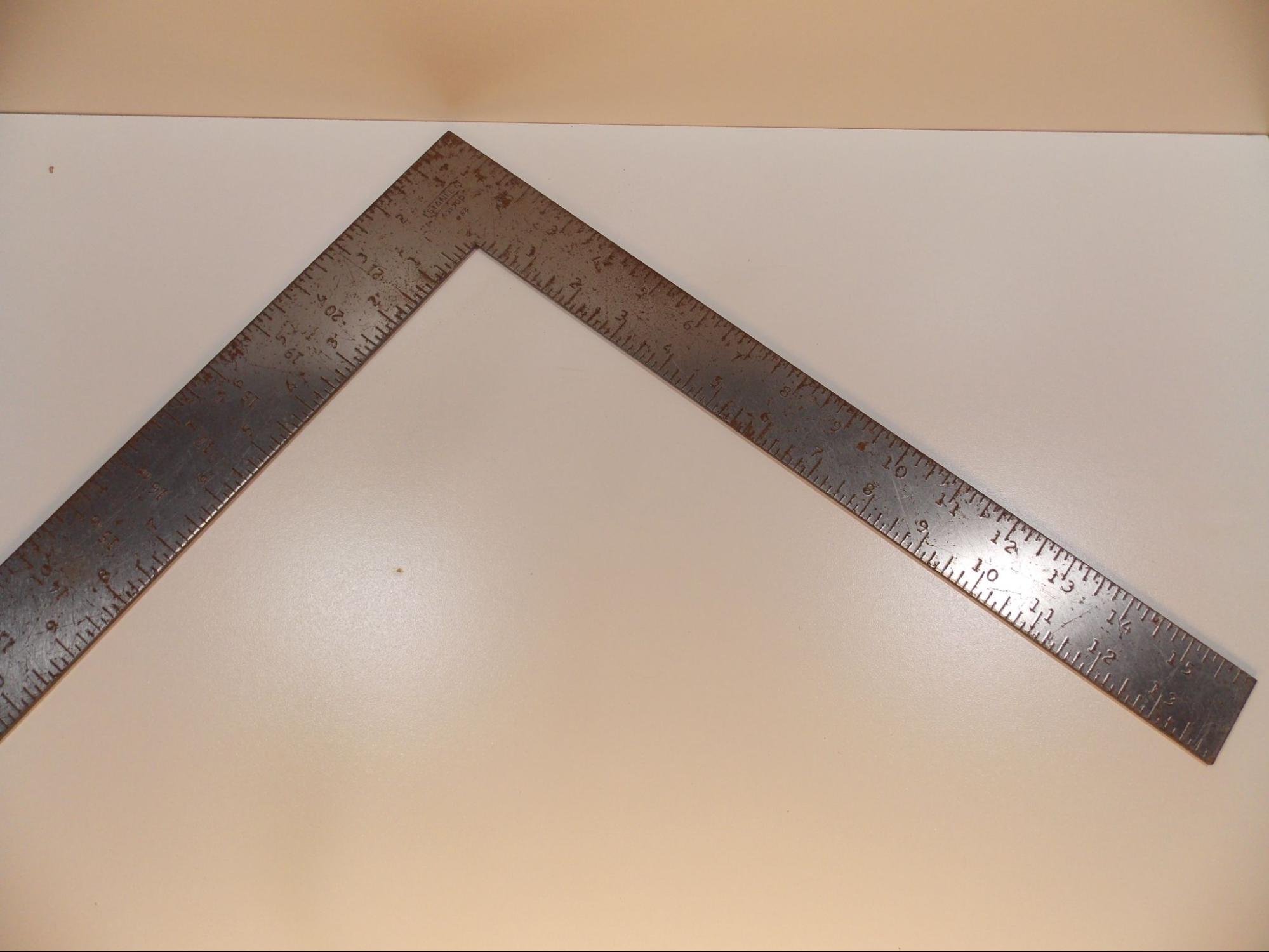
- Framing square
- Drywall square (also known as T-square)
- Machinist square
- Try-square
- Beam square
Welders and fabricators often work on round objects, such as pipe or round stock, so it is necessary to have tools, called pipe wraps, that are adapted to these shapes.
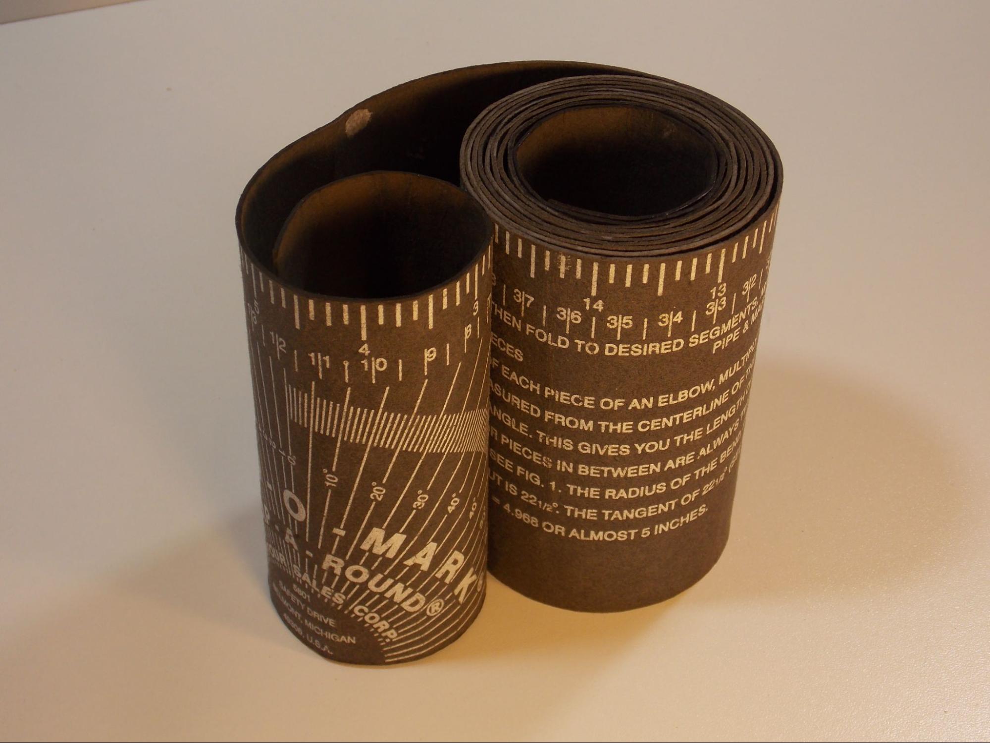
Pipe wraps are made of either cardboard, leather, or heavy fabric. They come as a long strip that usually is three inches or four inches (7.5 or 10 cm) wide and normally two to six feet (0.6 to 1.8 m) long and are usually rolled up for packaging. A pipe wrap works much like a square would on a flat piece of material: by wrapping the pipe wrap around the object, you can find square easily.
Another tool common for working with pipes is a centering head. It uses a level and a center punch to find the center of a pipe. Then, in conjunction with other squaring tools, you can find 90-degrees or any other angle on the pipe.
Tools for Finding Level, Plumb, and Angles
The term level refers to an object being perfectly horizontal. The term plumb refers to an object being perfectly vertical. Level and plumb are not dimensions but reference points. However, angular dimensions are often measured off of level or plumb, so you must know how to determine them. There are an assortment of tools for finding level, plumb, and angles.
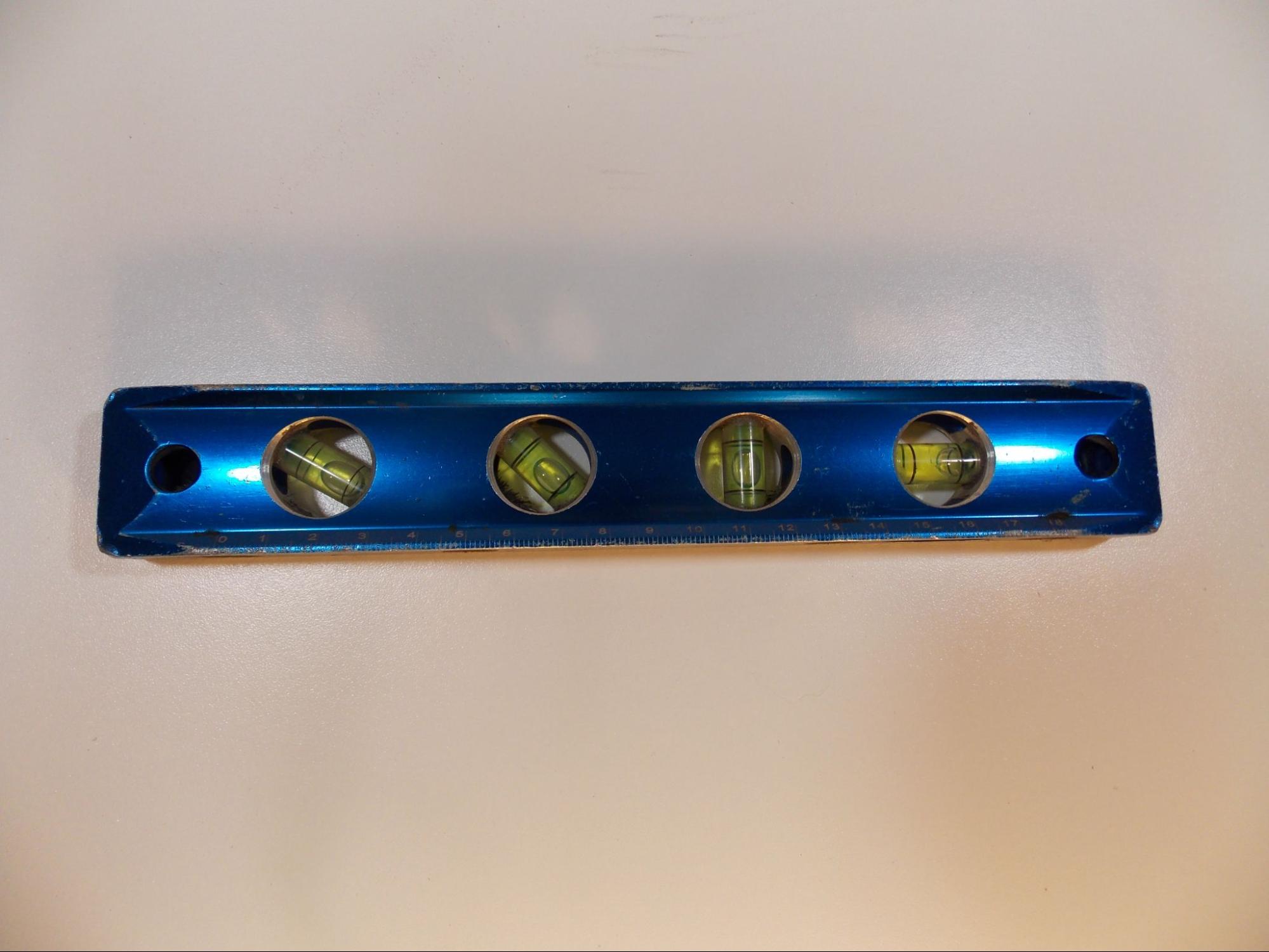
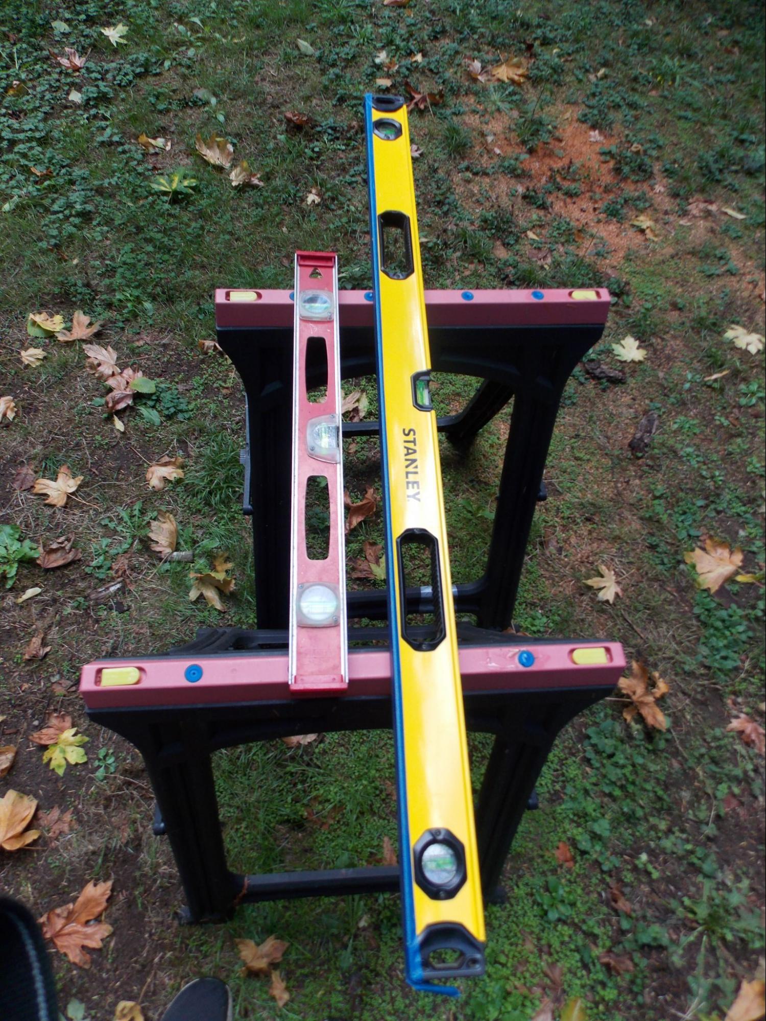
The most common tool for finding level is called a level, and it can also be used to find plumb. Levels use gravity to determine if something is horizontal or vertical: they contain a small clear tube of water with a single air bubble. When placed on a perfectly horizontal or vertical surface, the air bubble sits directly in the center of the tube. Levels come in many different sizes.
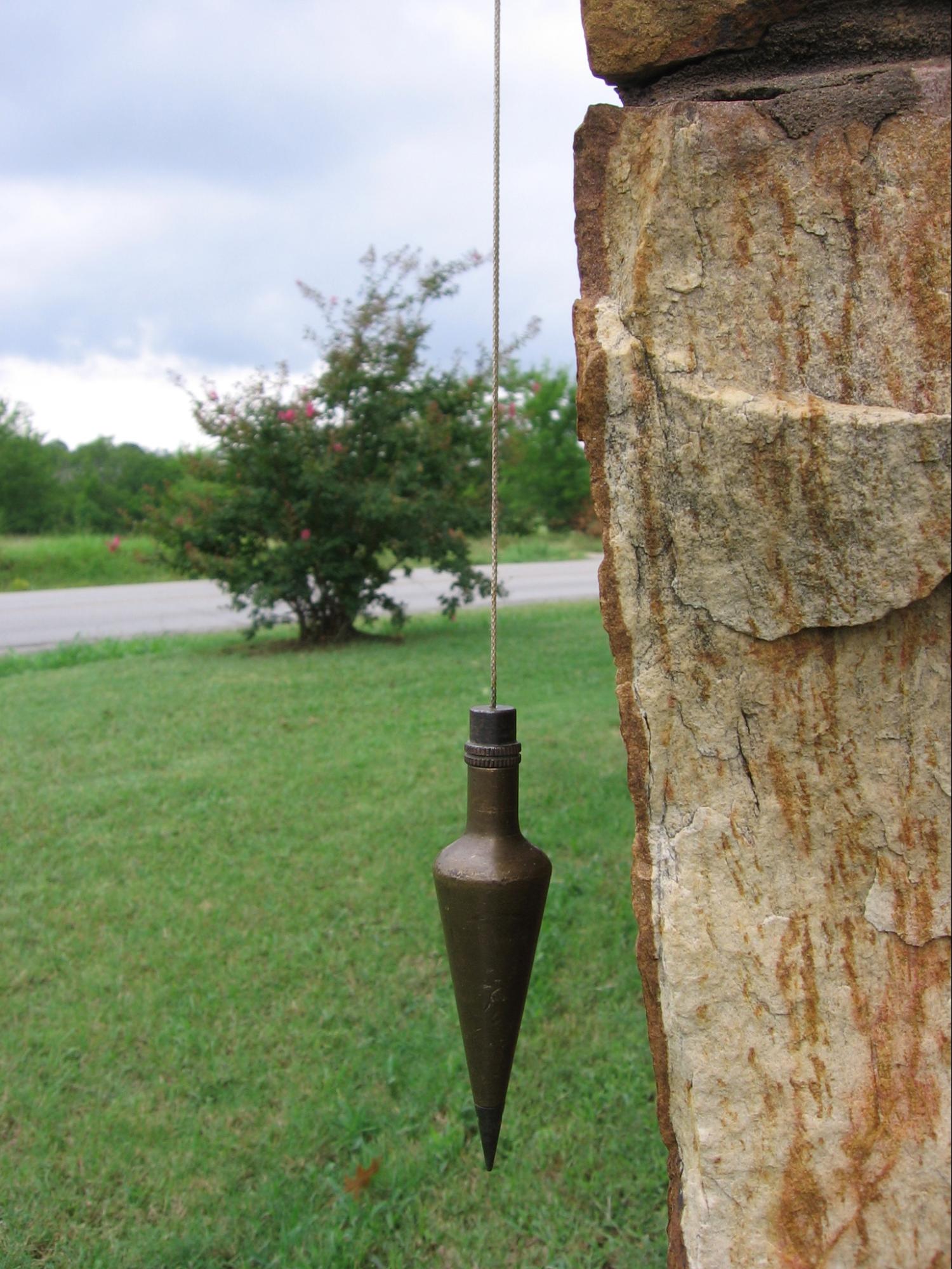
A plumb bob is a metal weight with a point on one end and a string attached to the other. To find whether an object is vertical, you hang a plumb bob next to it and measure the distance between the string and that surface. If the measurement is the same across repeated points, it is perfectly plumb.
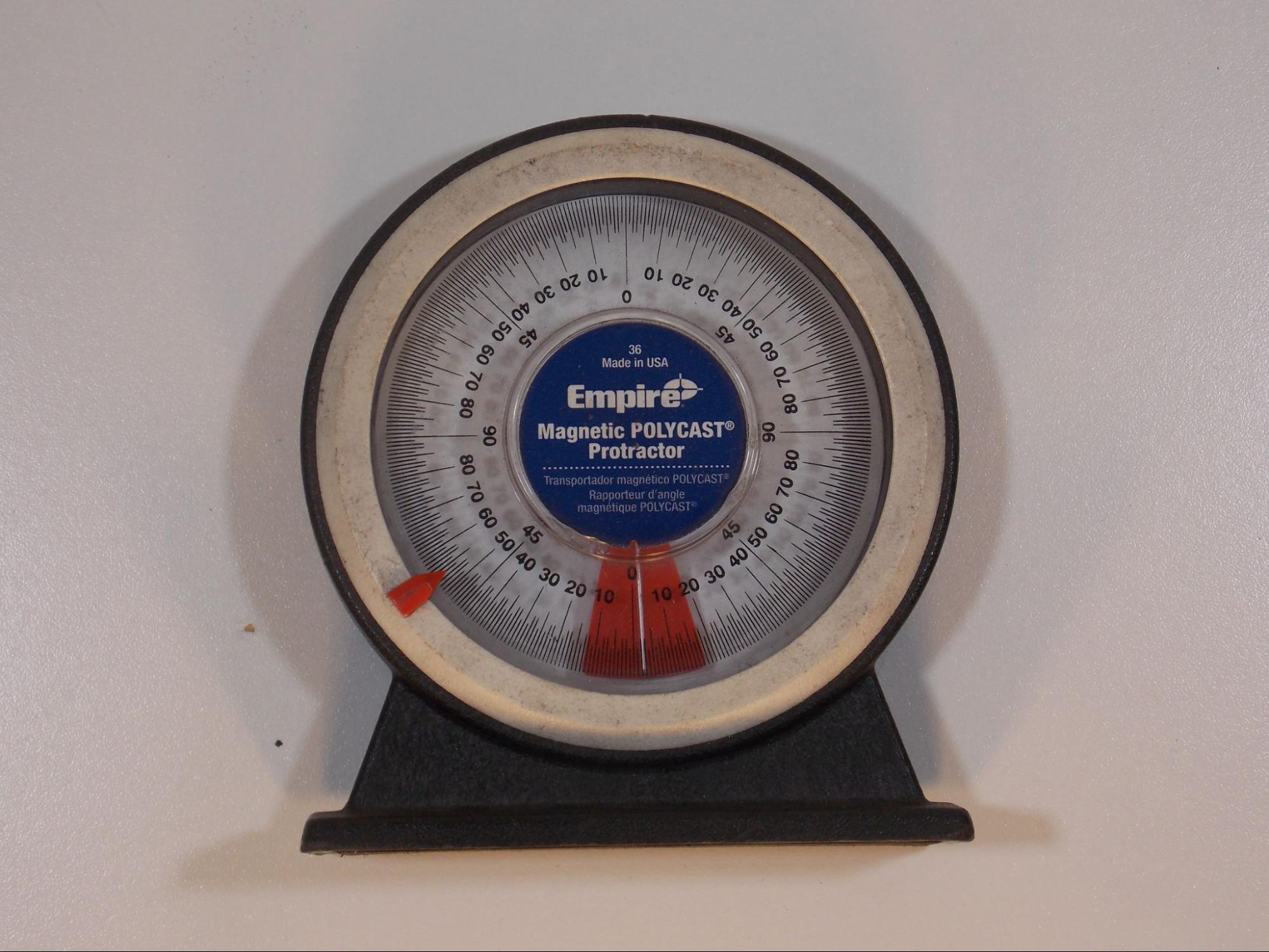
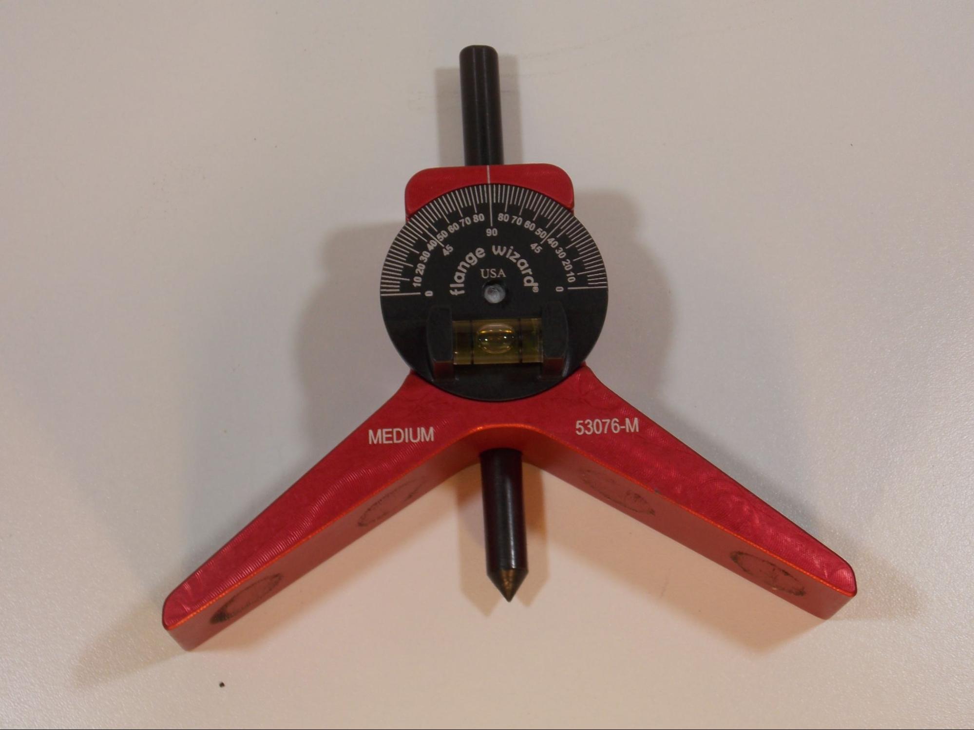
An angle finder could be used to measure for level and plumb, and it is also a handy tool for finding the resting angle of objects that you discover are not level or plumb.
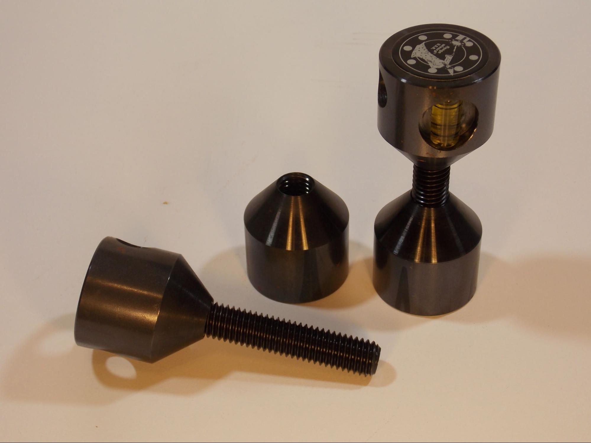
A set of hole pins can be used to level pipe flanges. They are inserted in the holes of the pipe flange and then a level can be balanced on them to make sure the flange is positioned correctly.
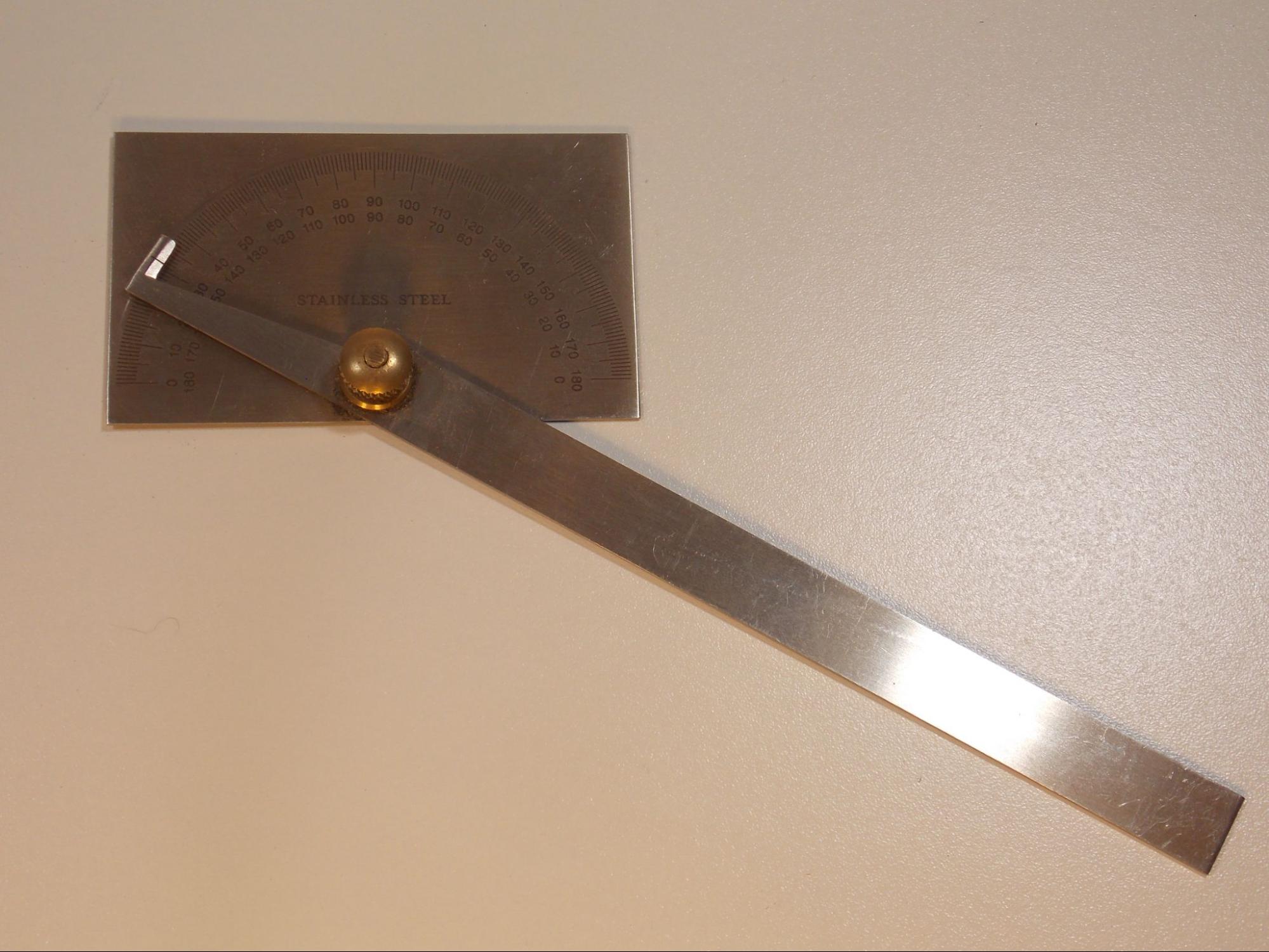
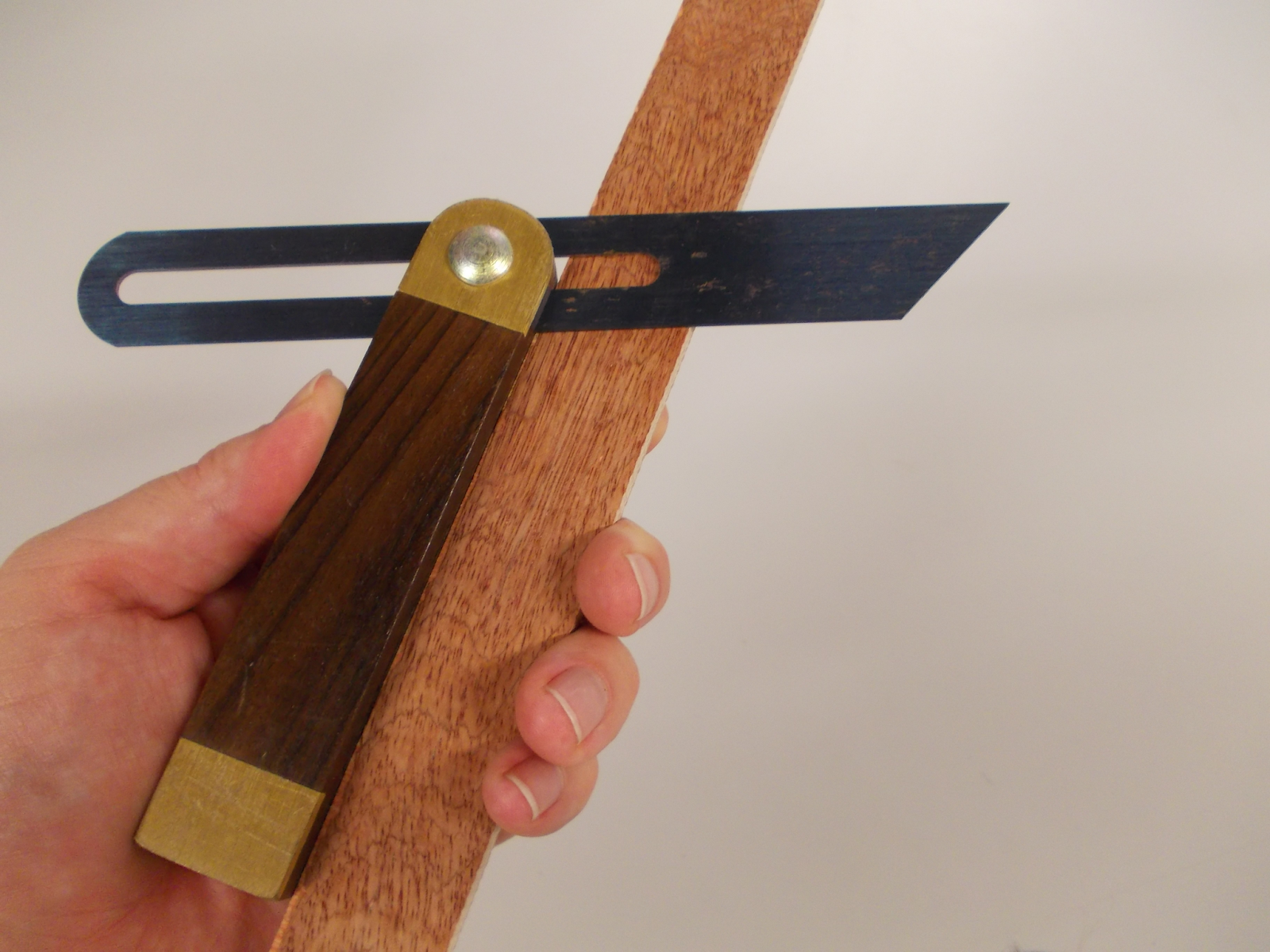
Protractors and T-bevels (also called a bevel gauge) are tools that can be used to find angles without referencing level or plumb. Compared to the tools mentioned above, which ensure objects are positioned correctly, protractors and T-bevels are used for laying out or checking different angles on parts.
Marking Tools
Once you have made a measurement, you will need a marking tool to label the location. Fabricators use many different varieties of marking tools and the kind you should use depends on the situation. First consider how precise you need to be. Generally, the finer a mark the tool makes, the more accurate your layout will be. Marking tools can broadly be divided into two categories: non-marring and marring.
A non-marring tool means that the mark isn’t permanent and will not blemish the surface of the material you are working on. Implements like silver pencils, grease pens, Sharpie markers, soapstone, and paint pens are non-marring.
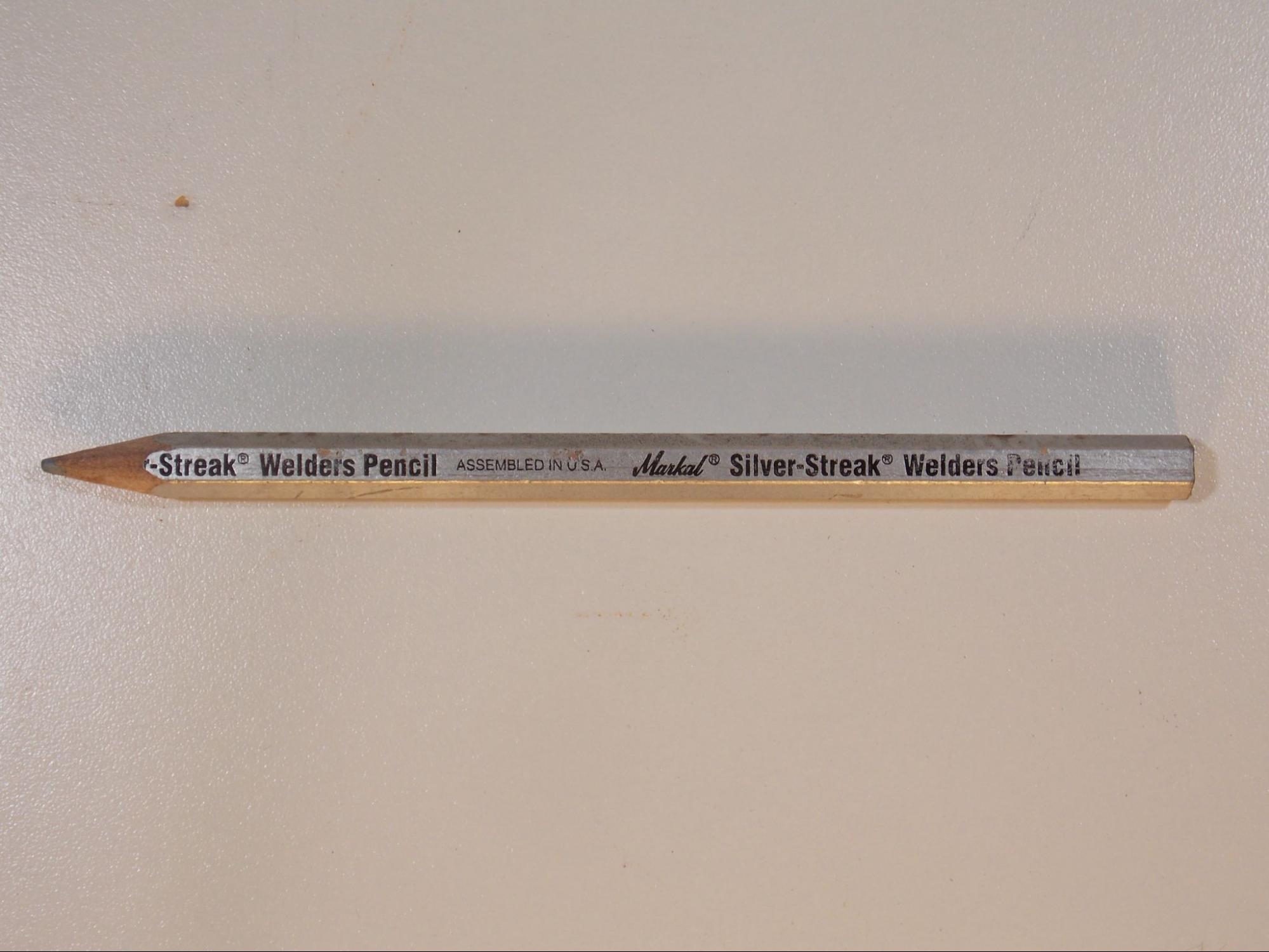
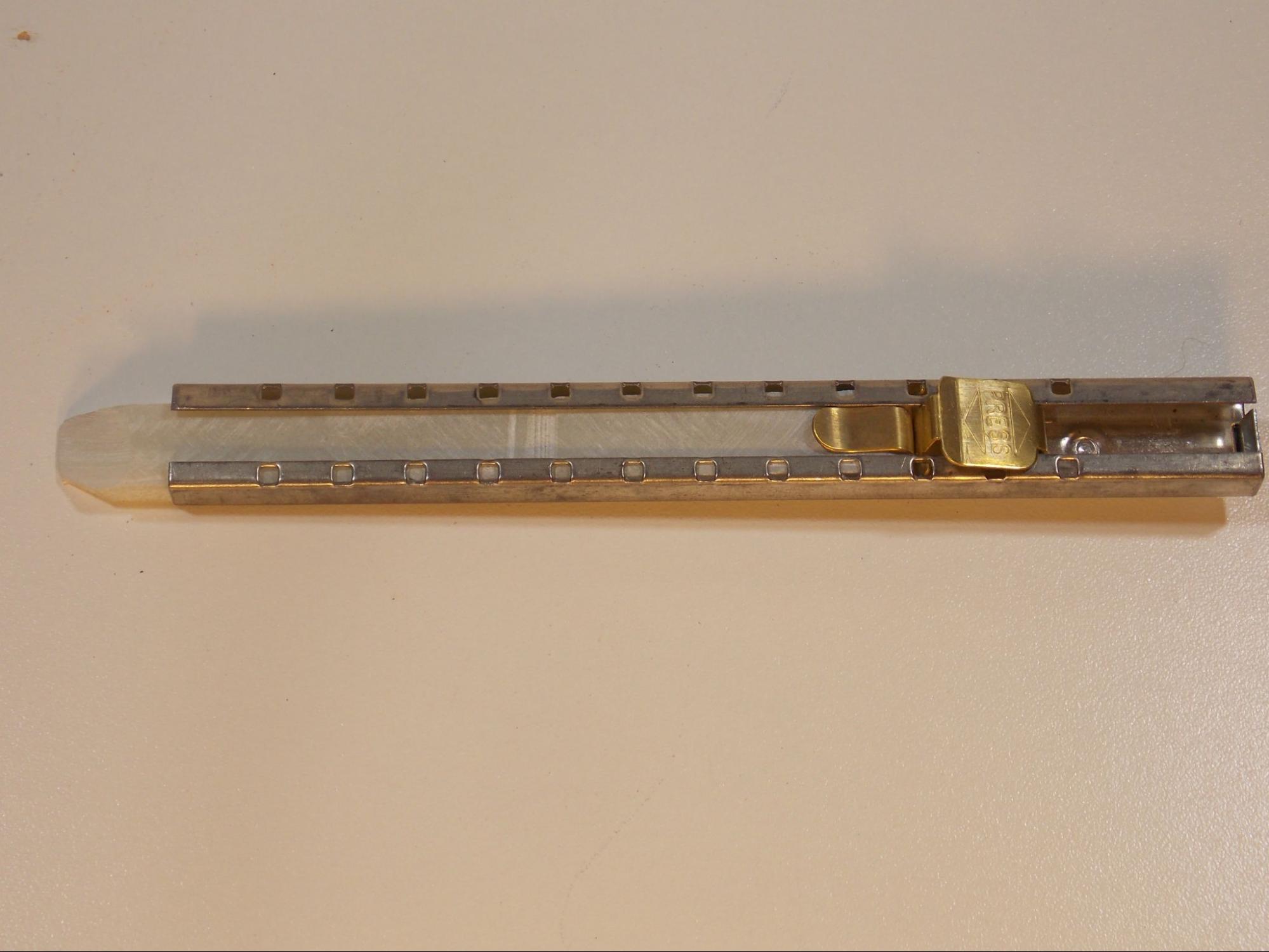
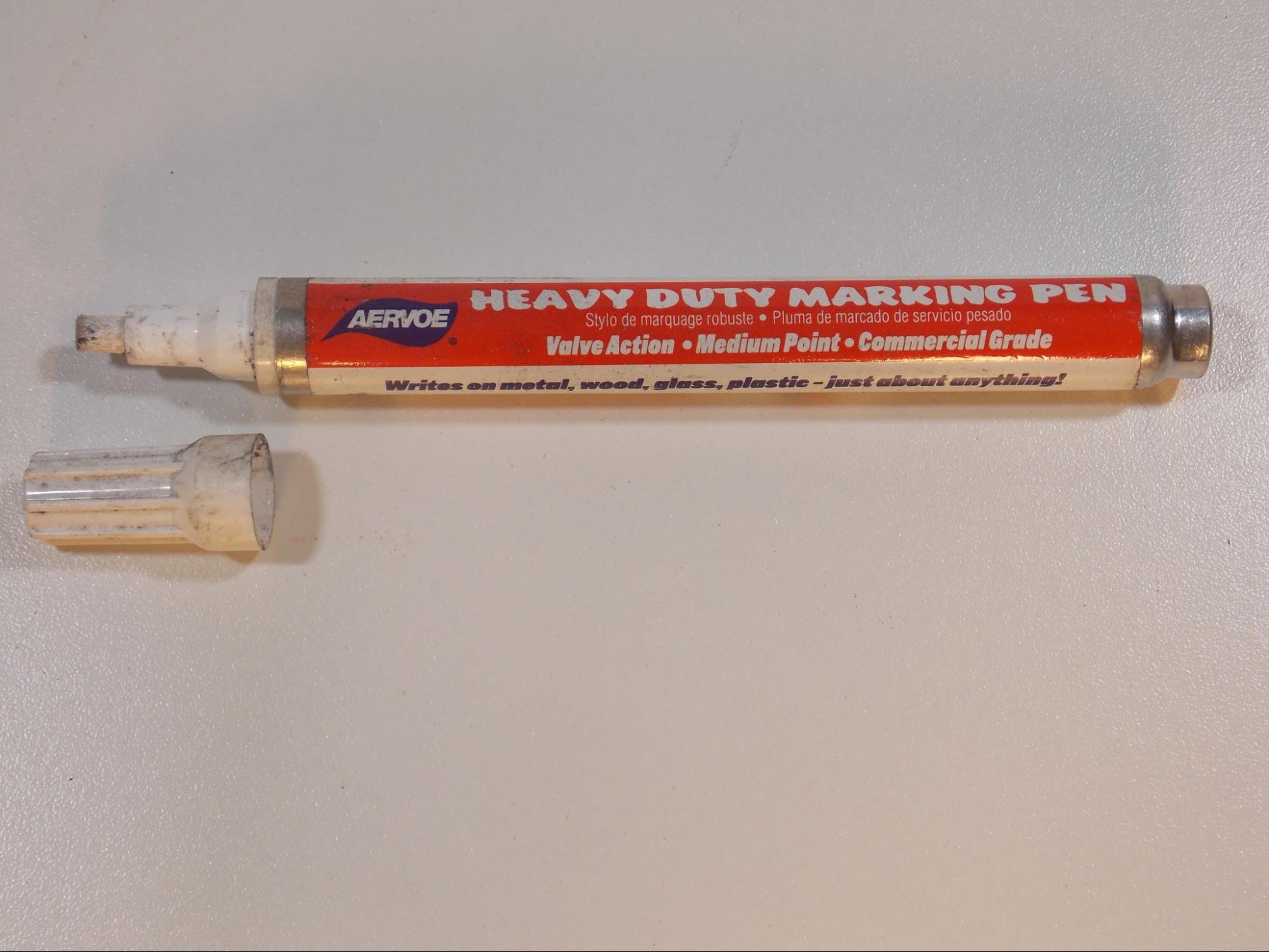
Keep in mind that the accuracy of your layout can be affected by the precision of your marking tool. Items like silver pencils and Sharpies can make fine enough marks for most things. Paint pens, however, tend to have wide marks that are easily smudged, so they are not recommended for precise layout. Soapstone can be sharpened to make very fine marks for great accuracy.
Another thing about non-marring marking tools to consider is the material you are working with and the work you intend to do on itl. For example, soapstone marks are almost invisible on aluminum. You wouldn’t want to use Sharpie markers on certain types of stainless steel because the ink can contaminate it. Silver pencil is very visible on steel, but if you were to mark some cut lines and then use a high-heat cutting process, like oxy-fuel cutting, the marks would melt away as you were trying to follow them. These examples illustrate how important it is to think ahead and choose an effective marking tool for the situation.
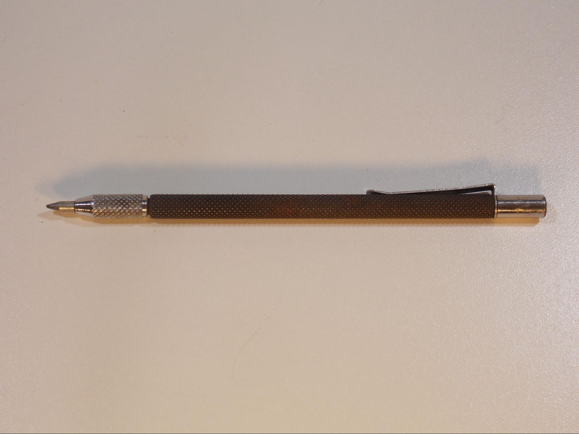
The other kind of marking tools, which are marring, make a permanent mark on the material surface, usually in the form of a scratch or indentation. The most common tools of this variety are scribes and punches. A metal scribe has a sharp hardened point that is used to scratch a very fine line on metal surfaces.
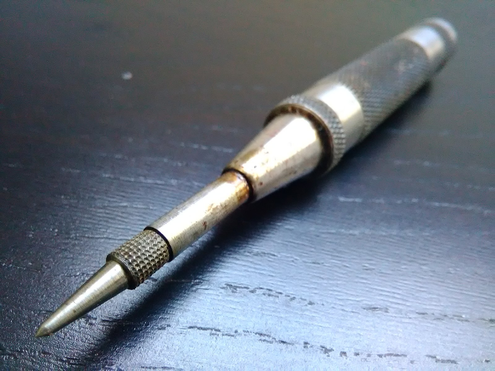
A center punch is used to make a single, small indentation in a metal surface. This can be used to mark a single point, such as the location of a hole to be drilled. You can also make a string of indentations to mark out a line; for example, to make a soapstone line more permanent. A center punch can be a single piece of metal with a point, the flat end of which must be struck with a hammer. There are also spring-loaded punches that allow you to make marks quickly and without the need for a hammer.
Depending on your employer and the job, it is not always permissible to put permanent marks on a workpiece. Instead, finish criteria often requires the surface of the material be as unblemished as possible, so be sure you know if making permanent marks on a piece is acceptable before doing your layout with these tools.
Fitting Tools
The term fitting is applied to the process of putting the pieces of a weldment together. Weldment pieces are often premade by a supplier, but fabricators may make them themselves.
The first step in fabricating any weldment is to make the individual pieces, and the second is to put them together. Fitting involves laying out the locations of all the pieces and making them fit together perfectly in relation to each other according to some blueprint or plan. But fitting is not as simple as just assembling all the pieces—many times the pieces do not fit together perfectly and require adjustment or alteration. This is by design, as it is usually better to have a little extra material that must be trimmed away than to have not enough material.
Fitting tools are another broad category of tools that a welder might encounter or need on the job. It is not an easy category to be specific about, as many welders or fitters actually fabricate their own tools to suit their needs at the moment due to the unpredictable nature of the design of weldments that they might be tasked to build. This section explores some of the tools you may use when you are fitting.
Fixturing and Holding Tools
A fixture is a tool that holds parts in place so they can be tack welded together. You will most likely also hear these called a jig. Fixtures can be any size or shape, simple or complex, homemade or prefabricated; it all depends on what you are building. The idea behind a fixture is to make putting parts together easier, especially if you are making multiples of the same weldment. Something as simple as a piece of angle iron can be a fixture for putting the edges of two plates together at 90-degrees. However, premade whole fixture tables can be bought.
Along with the fixture itself, you will need a variety of fixturing tools. Again, these can be purchased, but many welders make their own. These items include clamps, magnets, dogs, wedges, shims, and spacers.
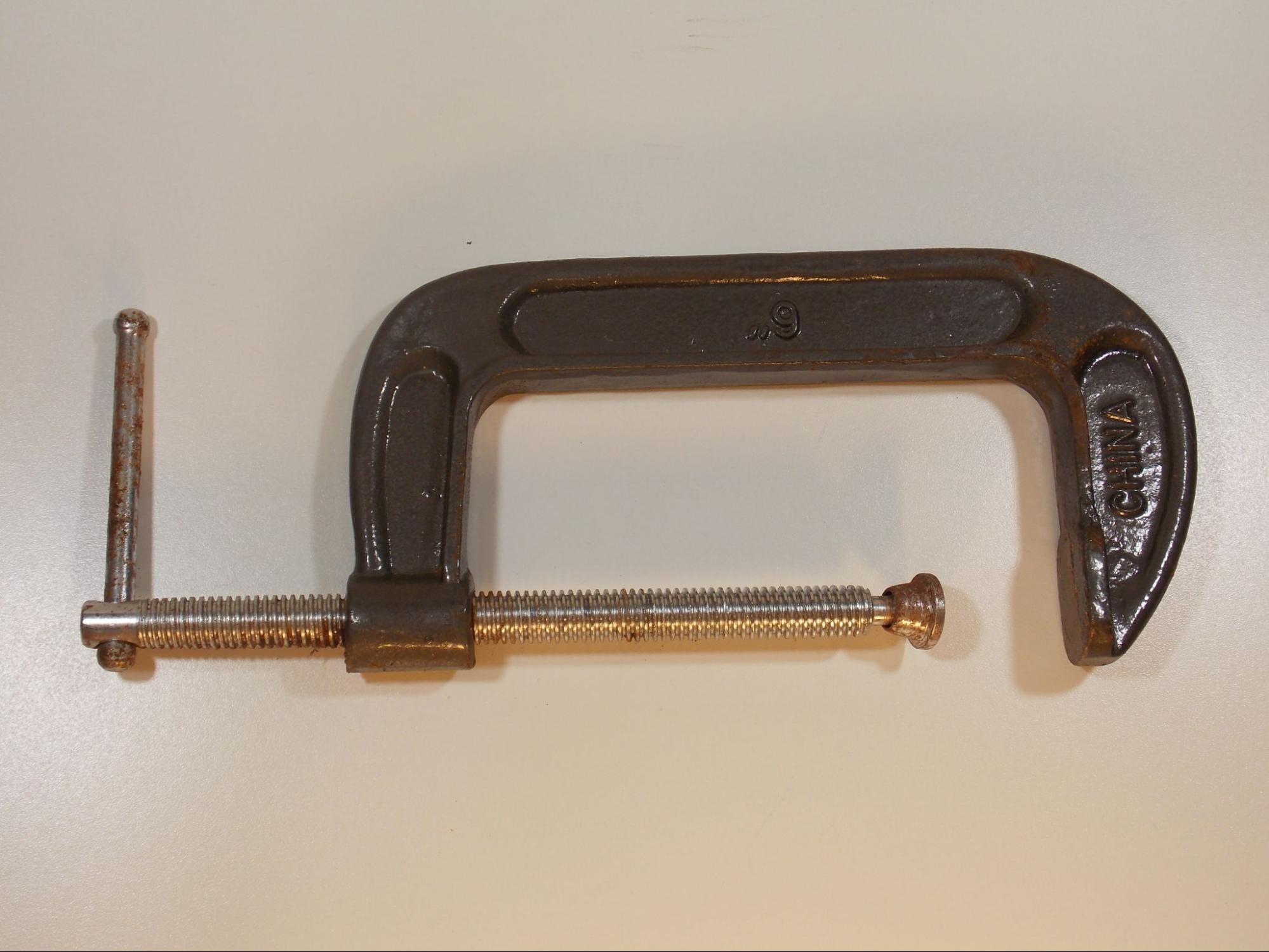
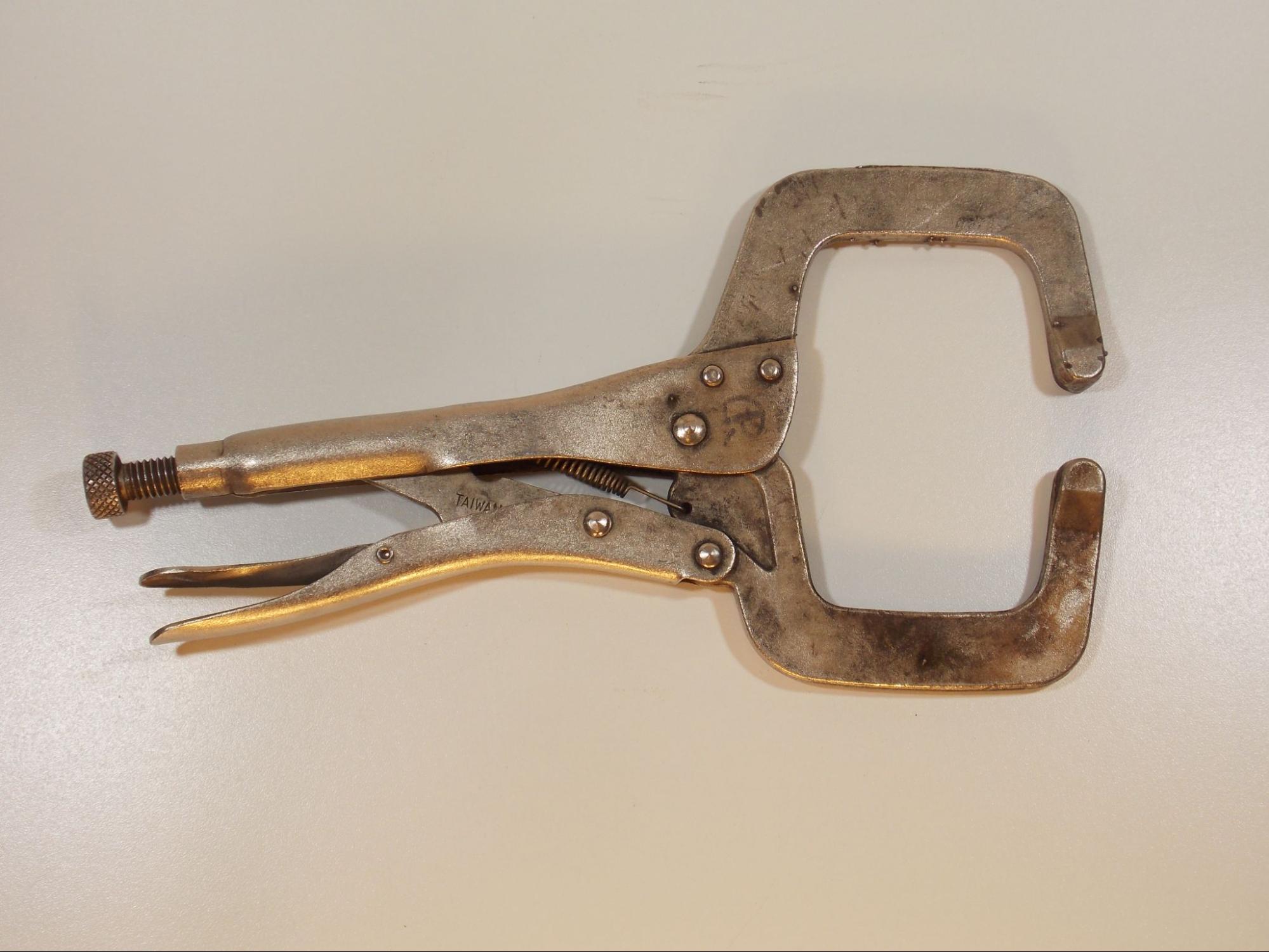
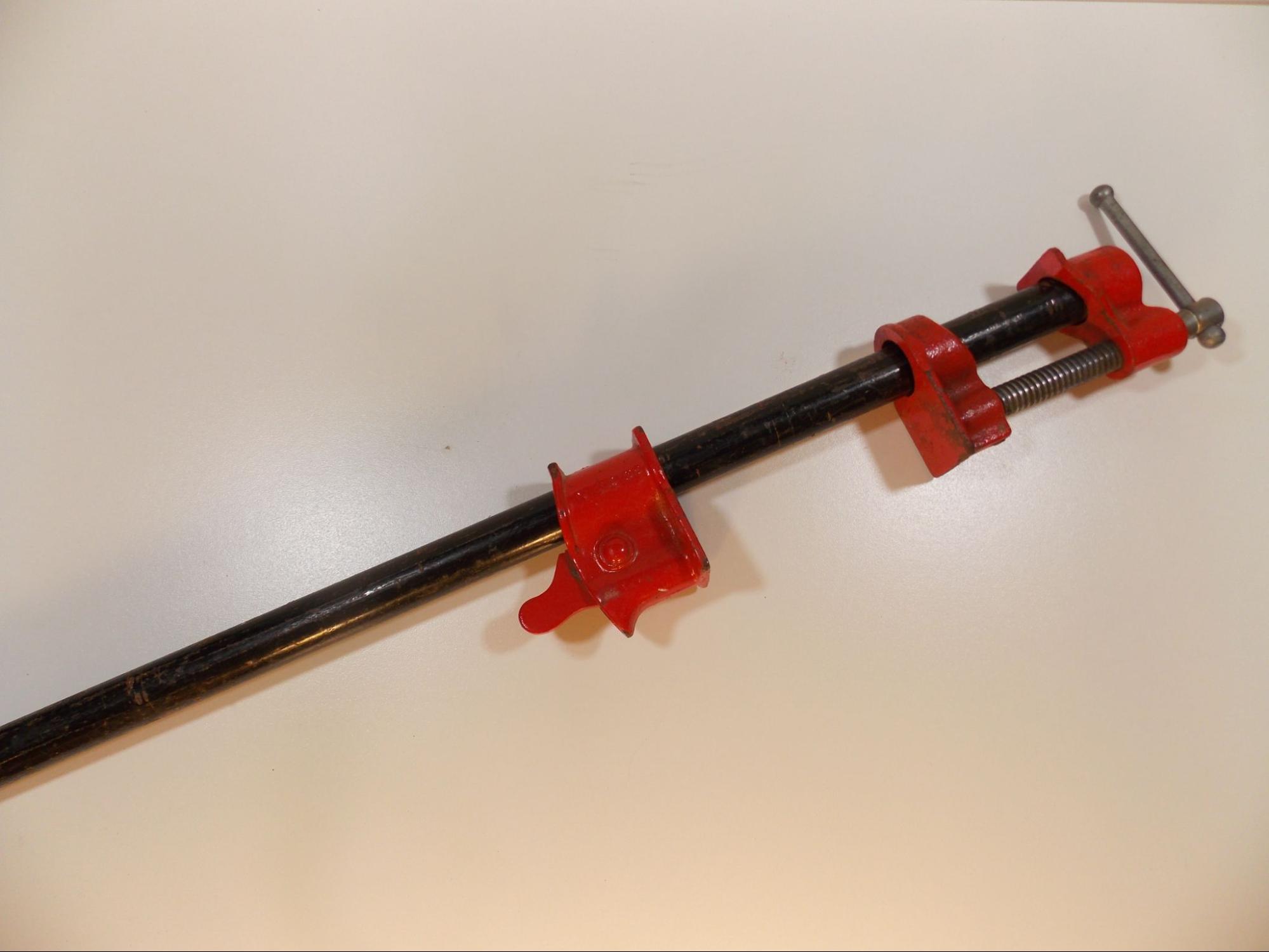
There is a belief among welders and fitters that you can never have too many clamps. They come in a wide variety of types and sizes, and you want to use a clamp that conforms to the shape and size of the part you’re using it to hold down. Some common clamps used in welding chops are C-clamps, #11 locking clamps, and bar clamps. Note that all of these clamps are composed of metal, and plastic clamps should not be used for welding-related applications. Some clamps are designed to work with fixture tables or be tack welded to a metal surface.
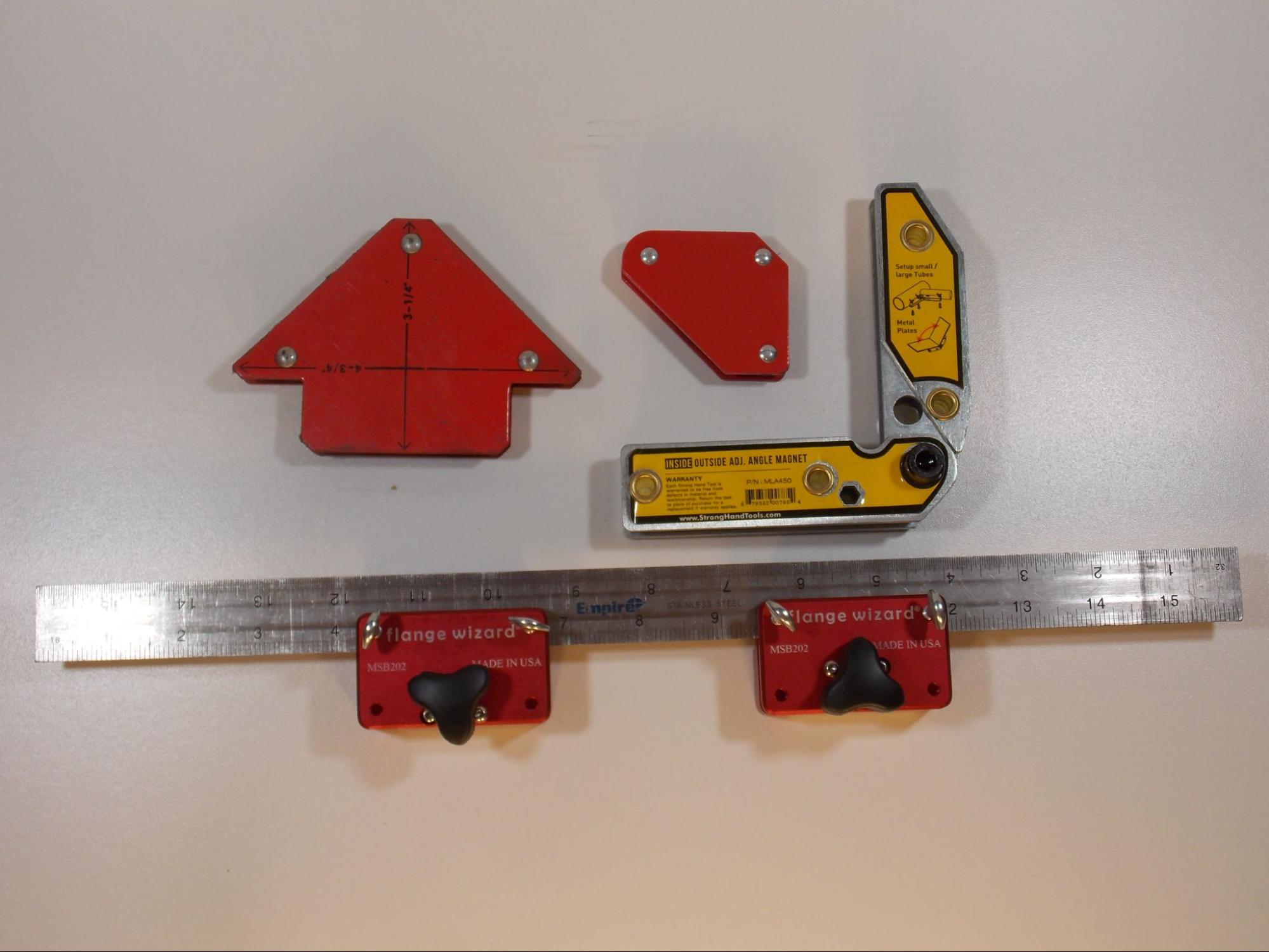
Another handy tool for holding metal parts in place is a magnet. Many magnets are made specifically for use in metal fabrication; however, any strong magnet can be useful for fitting.
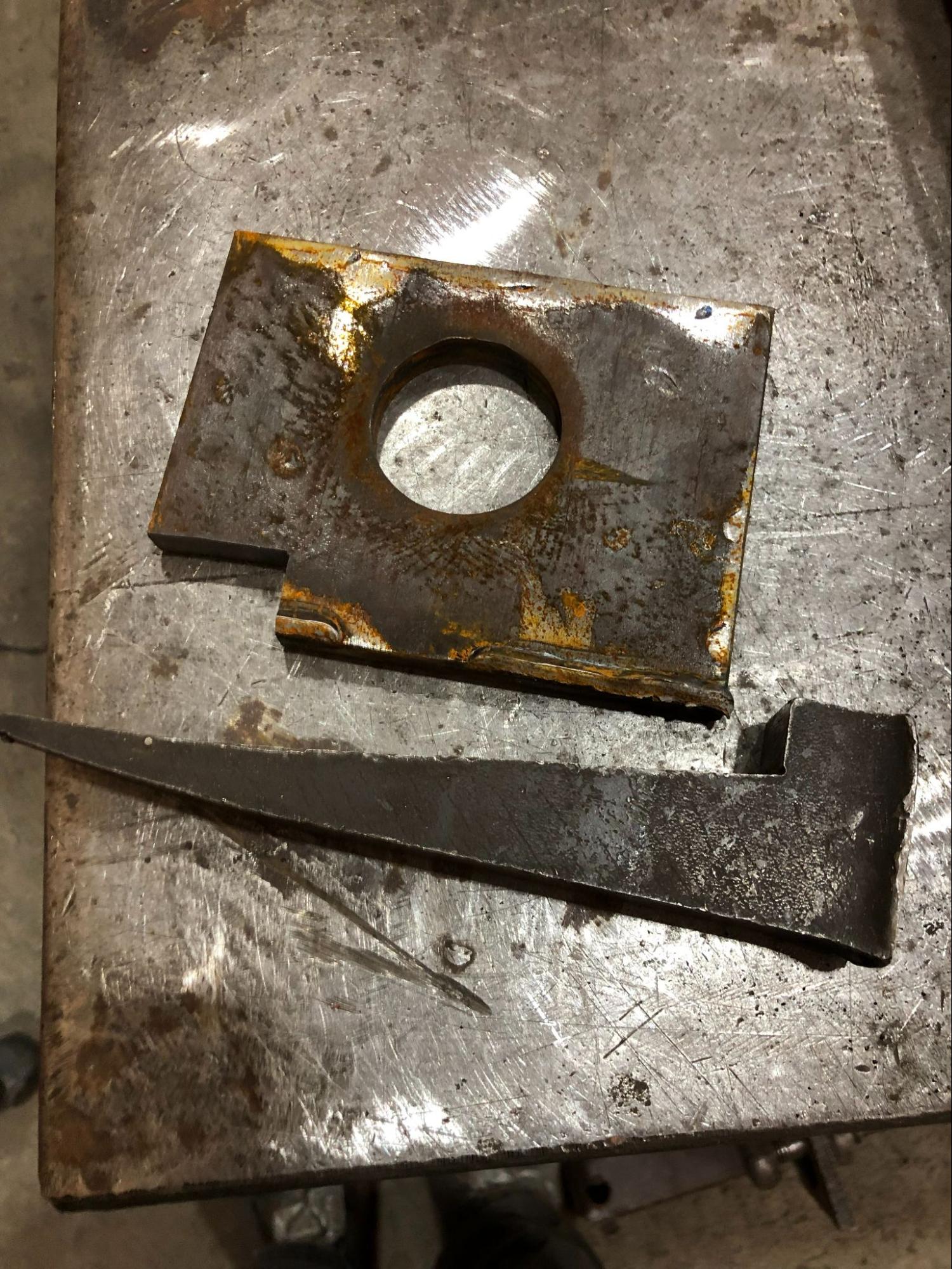
A dog is a piece of metal stock with at least one flat edge. Made in many shapes and sizes, dogs are used as a kind of backstop for parts being assembled. Dogs can be purchased or easily made out of scrap material. Some fixture tables have specially made dogs that come with them. You keep them in place by tack welding them to a metal surface or by the slots or holes in a fixture table. By placing dogs in strategic positions, you can even create a fixture on any flat metal surface for assembling parts.
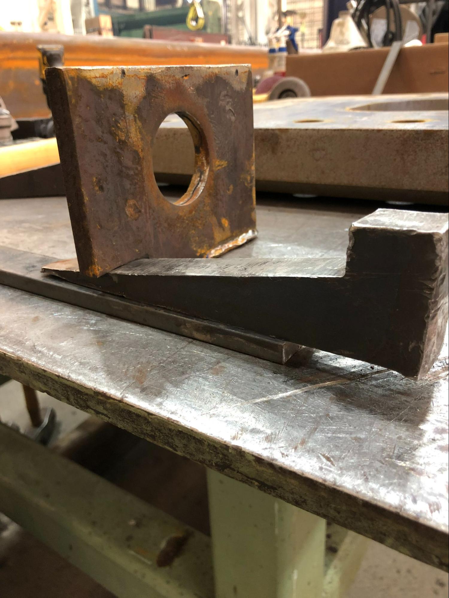
Dogs can also be used to hold wedges. As the name suggests, a wedge is essentially a piece of metal shaped like an acute triangle that is used to force a part into position. By driving a wedge between a dog and the weldment part with a hammer, you can exert a large amount of force on the part. Like dogs, wedges can easily be made from scrap material but can also be purchased.
General Hand Tools
Fabricators need an assortment of general hand tools, most of them determined by the industry they work in. Starting to build your tool kit can be a daunting task, as many tools are costly. A good rule of thumb is that if you need to borrow a tool more than once (assuming you are able to borrow tools), you should have one of your own.
It is good to have a small assortment of hammers. Ball peen hammers, light sledgehammers, and dead blow hammers are all common for striking parts to adjust their position. A dead blow hammer is used when working with soft material or when you must avoid leaving marks on the surface of a piece.
A set of files can be useful for deburring parts or lightly adjusting the shape of a part. You may find the need for a set of wrenches or sockets and a set of hex keys when working with hardware. Various types of pliers are always useful; specifically, 8-way pliers (which are often called welders pliers, MIG pliers, or Welpers, a brand name) are needed on a daily basis for most welders. A cold chisel and a scraper are useful for cleaning weld spatter or breaking small tack welds.
The type of welding you do will determine the tools you will need. For example, a TIG welder might need a tungsten grinder whereas someone who welds with FCAW may not. Start building your tool kit as soon as you can. Ask other welders around you for advice on which tools to use; most welders love talking about tools.
Attributions
- Figure 6.1: German Museum of Technology Berlin – 07TM-3438 by Jorge Royan is released under CC BY-SA 3.0
- Figure 6.2: Tape Measure by David Ridge, for WA Open ProfTech, © SBCTC, CC BY 4.0
- Figure 6.3: Measuring – Fractions of an inch by Offnfopt is released under CC0
- Figure 6.4: Tape Measure by David Ridge, for WA Open ProfTech, © SBCTC, CC BY 4.0
- Figure 6.5: Architectural scale by Mariko GODA is released under CC BY-SA 3.0
- Figure 6.6: image released under the Pixabay License
- Figure 6.7: Vernier caliper by Joaquim Alves Gaspar, modified by ed g2s is released under CC BY-SA 3.0
- Figure 6.8: Digital electronic vernier caliper, close up by Marco Verch Professional Photographer is released under CC BY 2.0
- Figure 6.9: Mahr Micromar 40A 0–25 mm Micrometer by Lucasbosch is released under CC BY-SA 3.0
- Figure 6.10: Parallel feeler gauge (imperial and metric)-92397 by Raimond Spekking is released under CC BY-SA 4.0
- Figure 6.11: Right angle by Gustavb in the Public Domain; This image of simple geometry is ineligible for copyright and therefore in the public domain because it consists entirely of information that is common property and contains no original authorship.
- Figure 6.12: Illustration of a combination square by Wellman Pattern Supply Co. in the Public Domain; This work is in the public domain in the United States because it was published (or registered with the U.S. Copyright Office) before January 1, 1928.
- Figure 6.13: Rafter (Speed) Square by David Ridge, for WA Open ProfTech, © SBCTC, CC BY 4.0
- Figure 6.14: Framing Square by David Ridge, for WA Open ProfTech, © SBCTC, CC BY 4.0
- Figure 6.15: SquareEngineersMachinist by Glenn McKechnie is released under CC BY-SA 2.0
- Figure 6.16: Pipe Wrap by David Ridge, for WA Open ProfTech, © SBCTC, CC BY 4.0
- Figure 6.17: Pipe Centering Head by David Ridge, for WA Open ProfTech, © SBCTC, CC BY 4.0
- Figure 6.18: Torpedo Level by David Ridge, for WA Open ProfTech, © SBCTC, CC BY 4.0
- Figure 6.19: Two-Foot and Four-Foot Level by David Ridge, for WA Open ProfTech, © SBCTC, CC BY 4.0
- Figure 6.20: plumb line on sandstone wall by P.W. Hatcher is released under CC BY-NC-ND 2.0
- Figure 6.21: Angle Finder by David Ridge, for WA Open ProfTech, © SBCTC, CC BY 4.0
- Figure 6.22: A Set of Two Hole Pins by David Ridge, for WA Open ProfTech, © SBCTC, CC BY 4.0
- Figure 6.23: Protractor by David Ridge, for WA Open ProfTech, © SBCTC, CC BY 4.0
- Figure 6.24: Bevel gauge by Luke Milburn is released under CC BY 2.0
- Figure 6.25: Silver Pencil by David Ridge, for WA Open ProfTech, © SBCTC, CC BY 4.0
- Figure 6.26: Soapstone by David Ridge, for WA Open ProfTech, © SBCTC, CC BY 4.0
- Figure 6.27: Paint Pen by David Ridge, for WA Open ProfTech, © SBCTC, CC BY 4.0
- Figure 6.28: Metal Scribe by David Ridge, for WA Open ProfTech, © SBCTC, CC BY 4.0
- Figure 6.29: Grabatu tresnak puntzoia 2 by Txikillana is released under CC BY-SA 4.0
- Figure 6.30: C-Clamp by David Ridge, for WA Open ProfTech, © SBCTC, CC BY 4.0
- Figure 6.31: #11 Locking Clamp by David Ridge, for WA Open ProfTech, © SBCTC, CC BY 4.0
- Figure 6.32: Bar Clamp by David Ridge, for WA Open ProfTech, © SBCTC, CC BY 4.0
- Figure 6.33: Welding Magnets by David Ridge, for WA Open ProfTech, © SBCTC, CC BY 4.0
- Figure 6.34: Dog and Wedge by David Ridge, for WA Open ProfTech, © SBCTC, CC BY 4.0
- Figure 6.35: Using a Dog and Wedge by David Ridge, for WA Open ProfTech, © SBCTC, CC BY 4.0
Fabrication, especially metal fabrication, is the entire process of building something out of metal. It can involve operations such as laying out dimensions on stock material, cutting, shaping, and forming the material, fitting and tacking parts together, weld out of assembled parts, and any finishing operations such as surface preparation or machining. A fabricator is a person or company who specializes in taking a project from stock material to finished product.
Layout is the process of finding and marking dimensions and locations on material, either for the purpose of cutting the material to size or length or fitting up parts to assemble a weldment.
A weldment is anything composed primarily of metal and is held together by welding.
Tolerances are a guideline on how much a part or weldment can deviate from being perfect, and are meant to maintain a certain level of quality while also making it easier for the product to be built.
A system of measurement in which the units are broken up into, Length: Inches, feet, yards, miles. Weight/Mass: Ounces, pounds, tons. Volume: Fluid ounces, pints, quarts, gallons.
A decimal-based system of measurement used globally (except for a few countries like the U.S.). It standardizes units for length (meter), mass (kilogram), volume (liter), and other quantities.
An object or a face of an object is true if it is perfectly straight.
A part of an object is square if one face of the object is perfectly 90o from an adjoining face.
Stock material, especially metal stock, is material for construction that comes preformed in certain shapes and dimensions, such as angle, chanel, bar stock, pipe, tubing, and plate.
An object is level if it is perfectly horizontal as determined by the earth's gravity.
An object is plumb if it is perfectly vertical as determined by earth’s gravity.
Fitting is the process of assembling the parts of a weldment. It involves accurately positioning parts according to the blueprints and tack welding them in place, as well as adjusting part dimensions if necessary. A fitter is someone trained to accurately assemble the parts of a weldment.
A fixture is a tool used to hold the parts of a weldment in place for fit up or welding. A fixture can be as simple as a piece of angle iron used to fit up a 90o corner or as complex as a fixture table equipped with a variety of clamps, dogs, and part holders. You may hear a fixture also called a "jig".
A tack weld is a small weld made to hold parts together during assembly and is usually not meant to be permanent.

-92397.jpg)