8.2 SMAW Equipment and Setup
David Ridge
Components
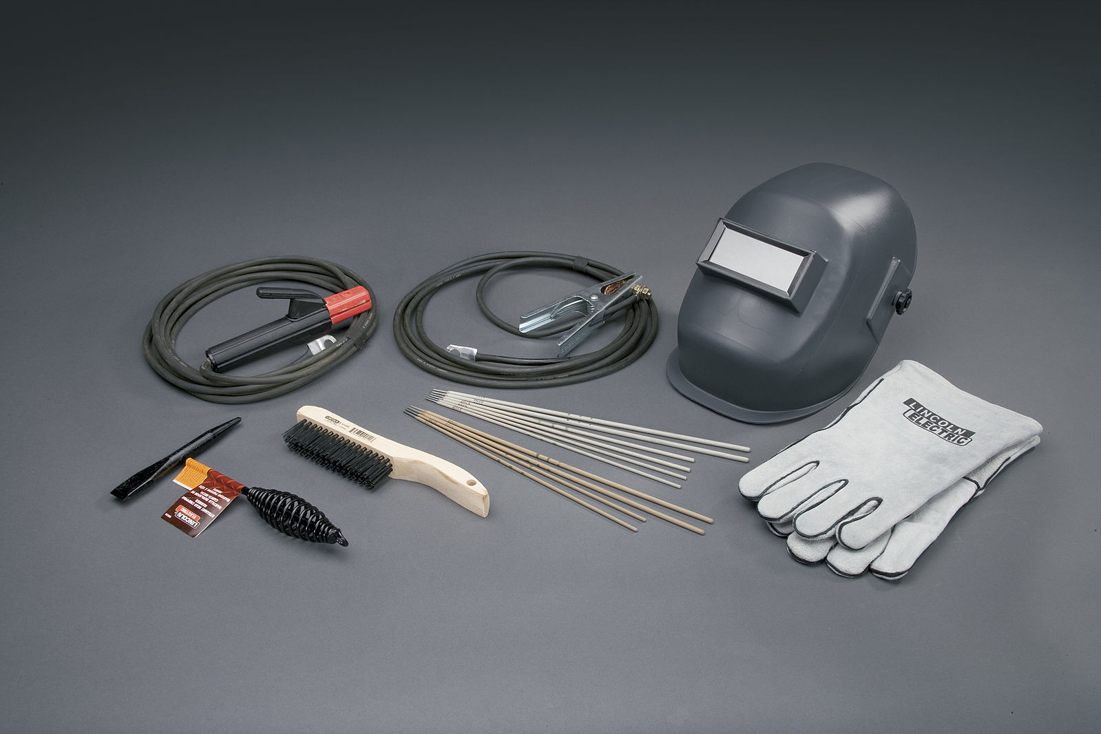
SMAW is one of the simplest welding processes as far as the amount of equipment needed. There are only four main components to the system:
- a welding power source,
- a workpiece lead,
- an electrode lead, and
- coated metal electrodes of the appropriate alloy.
The following sections discuss these components in detail.
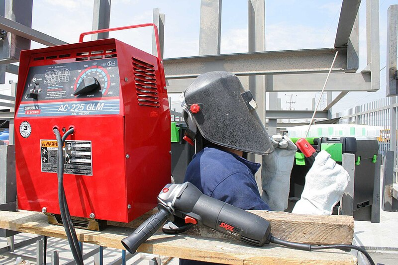
Welding Power Source
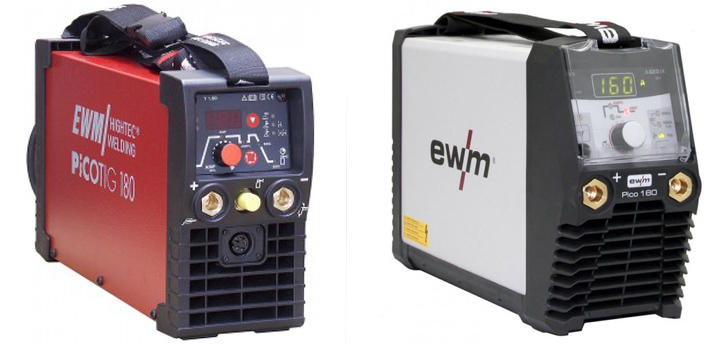
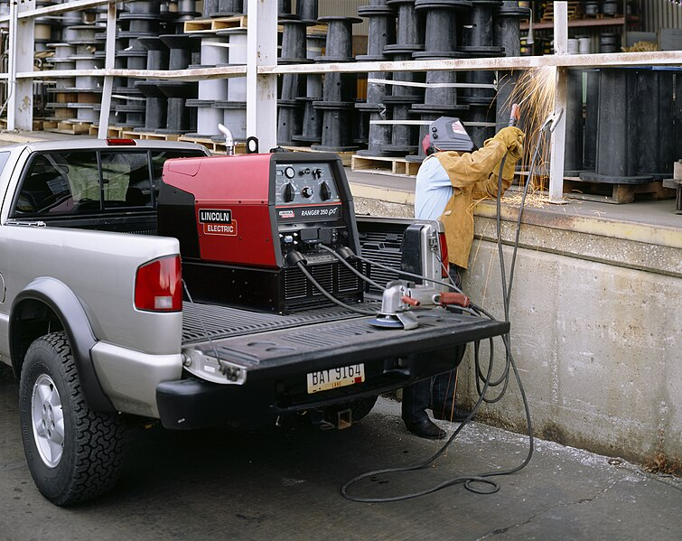
A welding power source is a machine capable of producing the specialized electrical current necessary for arc welding. These machines can vary widely in design, capability, and size, but, in general, they can be divided into three types: transformers, inverters, and engine-driven varieties. You will often hear the welding power source called a welding machine or simply a welder on the jobsite.
Welding power sources will be discussed in greater detail later in this chapter, and they are also covered in Chapter 5: Welding Machines.
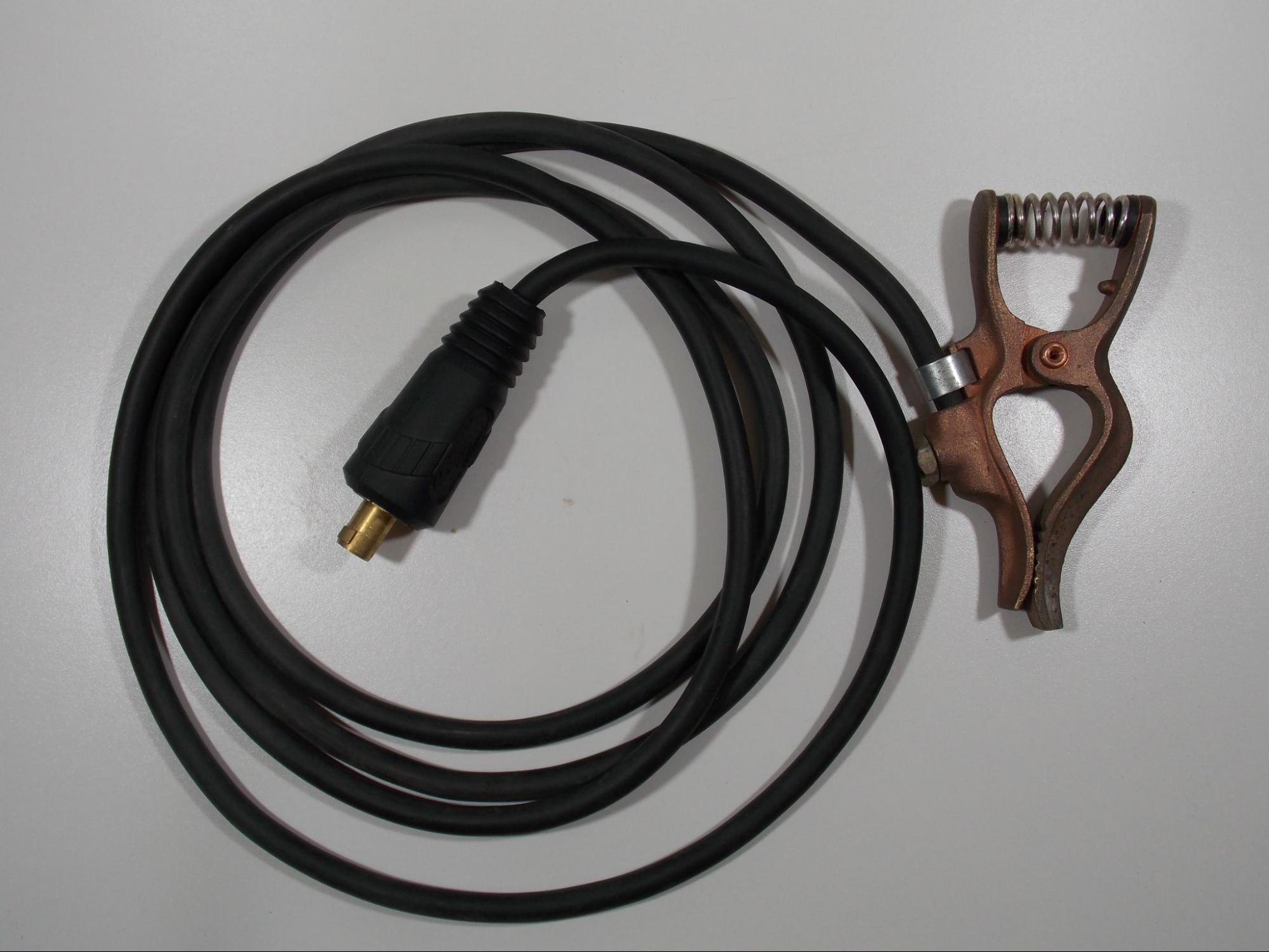
Workpiece Lead
The workpiece lead is used to make the electrical connection between the welding machine and the base metal. You may hear the workpiece lead called the work lead or a ground lead (although this is inaccurate).
Welding leads are made of many small strands of copper wire twisted together into a cable and covered in a protective rubber sheath. Welding leads vary in diameter and length depending on the welding application.
The workpiece lead is attached to the base metal using either a clamp or a lug. A lug can be connected to a threaded stud, which is then welded to the base metal. These clamps and lugs are usually made of copper or brass; however, you may see some clamps made of steel. Though less common, there are also magnetic work clamps.
The other end of the workpiece lead is connected to the welding machine via a special plug called a twist-lock connector. This plug inserts into a receptacle on the welding machine and then twists to lock it in place. If not connected in this way, the lead is usually attached using a lug, or in some cases, it is permanently wired into the machine.
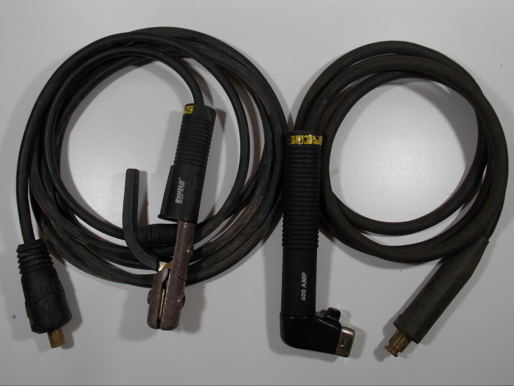
Electrode Lead
The electrode lead runs from the welding machine to the electrode holder. This is the piece that the welder holds in their hand in order to make the weld. You may often hear this piece called the stinger or the whip.
The electrode holder transfers the welding current to the electrode. There are several styles of electrode holders, and the most common are the alligator clamp style and the twist-lock style.
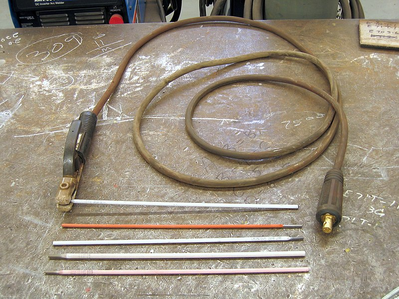
Coated Metal Electrodes
The SMAW electrodes are metal rods commonly ranging from 9–18 inches in length, although longer ones may be found. These rods usually range from one-sixteenth of an inch to one-quarter of an inch in diameter. Larger diameters are available but are usually only used for special applications.
The rods are sheathed in a flux coating. The flux has several purposes, the first of which is to protect the weld from the atmosphere during welding. This is primarily accomplished by the gas cloud and the slag cover that was mentioned earlier. Another way that the flux helps remove contamination from the weld is through deoxidizers, which are chemical elements such as silicon or manganese. These elements chemically clean the weld by attaching themselves to contaminants, such as sulfur, while the weld metal is a liquid, then floating them to the surface to become part of the slag.
Other components of the flux include arc stabilizers and fluxing agents. Arc stabilizers help maintain the welding arc during welding. An electric arc is naturally unstable and wants to wander and fluctuate in intensity (for a comparison, think of how crooked and uneven a lightning bolt is). Arc stabilizers keep the arc aimed where the operator wants it, help keep the heat of the arc focused on the weld pool, and help prevent the arc from sputtering or cutting out. Fluxing agents (not to be confused with the flux coating itself) make the weld metal more fluid, allowing it to flow out from the point where the arc meets the base metal. Even though molten metal is in a liquid state, it is very viscous and has a high surface tension. This property keeps the weld from spreading out over the base metal, making it pile up in one narrow area. Fluxing agents help counteract this effect.
The type of metal that can be welded with each different SMAW electrode is determined by the metal alloy that the rod is made of, as well as the type of flux coating that it has. Also, the diameter of the rod and the type of flux determine the type and amount of electrical power needed to make the weld. A system for identifying the different welding electrodes has been developed by the American Welding Society (AWS)—this system and its application will be discussed later in this chapter.
Setting Up the Welding System
Although SMAW does not require a lot of equipment and setting up and adjusting the welding system is not difficult, there are some key points that should be taken into account when preparing to operate a welder for SMAW.
This section discusses how to safely set up a SMAW system.
Safety Considerations
When setting up the welding system, it is necessary to consider the amperage ratings of components such as welding leads, electrode holders, clamps, and connectors. Each of these components comes in a range of sizes that are rated for different amperages.

The amperage rating for each component can be found in the user’s manual, product information slip, or printed on the component itself. It’s essential to be sure you are using components that are rated for the amperage you will be using because using a component at an amperage beyond its safe working rating can damage that part or other parts of the welding system. Always refer to the manufacturer’s recommendations when setting up a welding machine. This will help you understand how much power your machine and its components are rated for and the necessary electrical safety requirements.
Damage to parts may occur in other ways as well. Welding shops and construction sites can be harsh environments that result in damaged system components, which can be dangerous when working with hundreds of amps of electricity. All of the parts that are electrically “hot” are shielded to keep you from coming into contact with them, but damage could mean the live electrical components become exposed. Additionally, damaged parts almost always cause resistance in the welding circuit, which causes heat. For example, a worn out work clamp can get so hot from the additional resistance that it can cause burns if you touch it. Testing electrical connections to see if it is hot before touching it is always a good idea, especially if you have been welding consistently for a while. Another aspect of added resistance in the system is that it almost always makes your welder run poorly, making it very difficult to make a good weld. Before welding, have any damaged parts repaired or replaced and check all connections in a welding system to make sure they are tight. Loose connections can also cause heat to build up in the system, which can, in turn, cause damage.
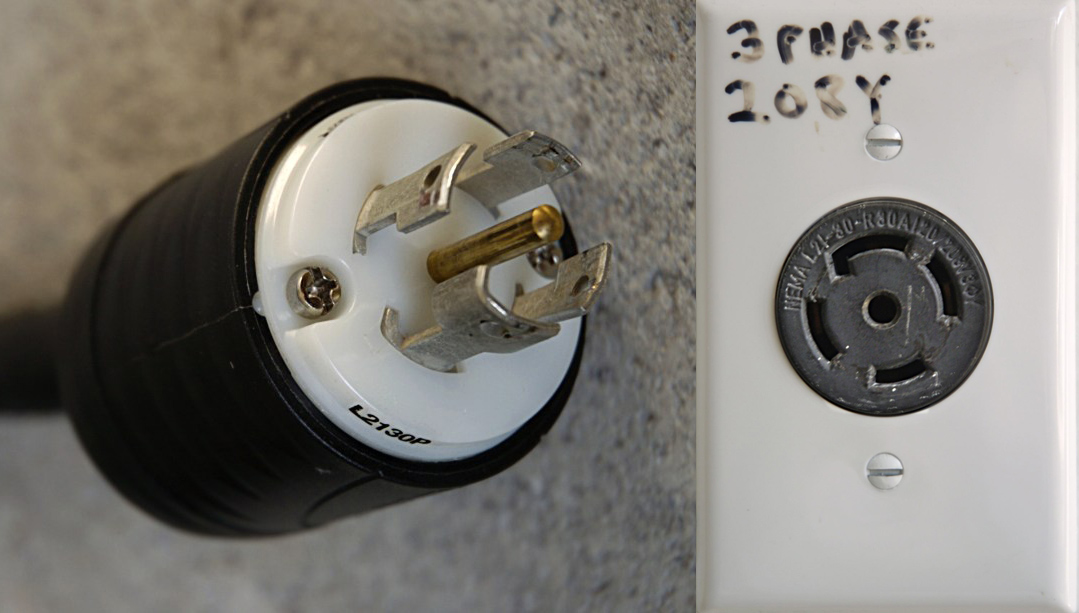
One last safety consideration to be mindful of when setting up your welding system is the service power you are plugging the machine into. While some welders can be plugged into a standard 110V/120V wall outlet, most production welding systems require a 220V/240V or even a 440V/480V circuit. Even if you can plug a welder into a standard wall outlet, welders usually require a 20 amp circuit breaker at minimum, which is not standard in most residential circuits. In the case of higher voltage circuits, a 30 amp or 50 amp breaker may be required. It is very important that you be sure your electrical supply is adequate for the machine you are running.
All work performed on electrical service supply should be done by a professional, and it is never your responsibility as a welder to work on these systems. If you encounter any damaged systems or equipment, do not attempt to fix the problem yourself. Instead, follow proper lockout/tagout procedures and notify the appropriate personnel.
SMAW Setup
Once you have ensured that all parts are in proper working order, you can begin to set up the welding system. The first step is to plug the welding power source into the appropriate wall outlet. If the outlet is at least a 220V/240V outlet, the plug and receptacle may be a twist-lock connector (meaning that you insert the plug and twist clockwise to keep the cord from falling out).
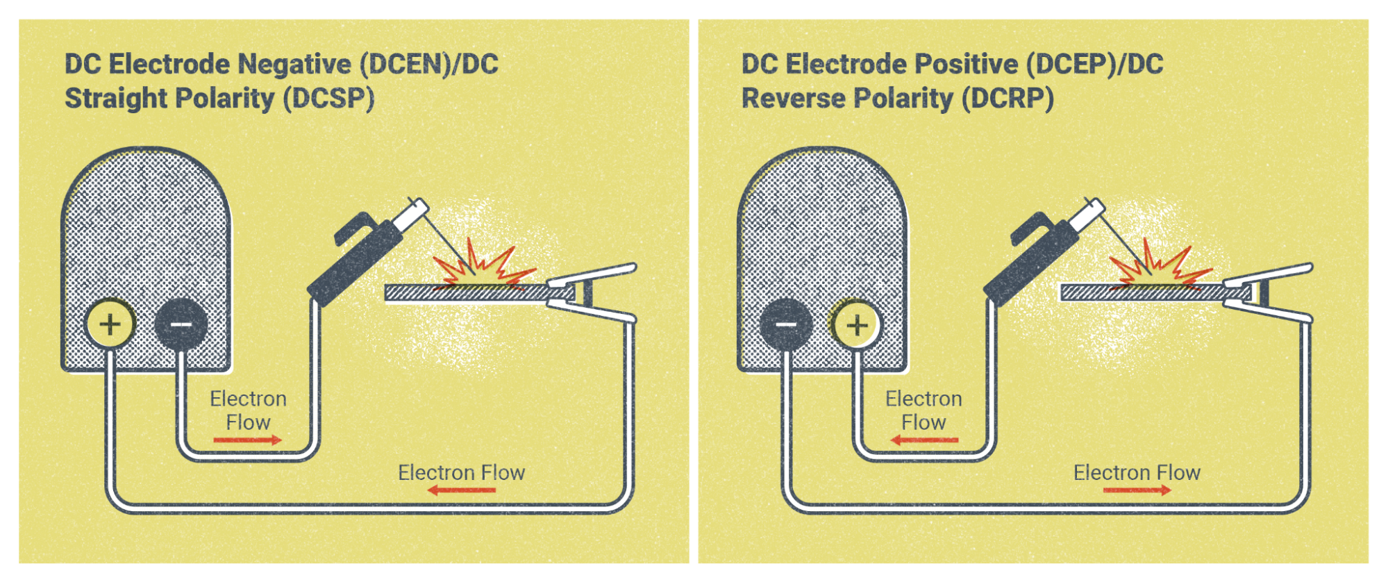
The next step is to attach the welding leads to the welder. The welder should have two different attachment points: one will be positive, and the other negative. The electrode you will use determines how you need to hook up the leads. Most welding electrodes require the welding circuit to be connected in DCEP. This means that the electrode lead is plugged into the positive terminal of the welder, and the work lead will be plugged into the negative terminal. If you needed to connect the leads in DCEN configuration, you would simply switch the electrode lead to the negative terminal and the work lead to the positive terminal.
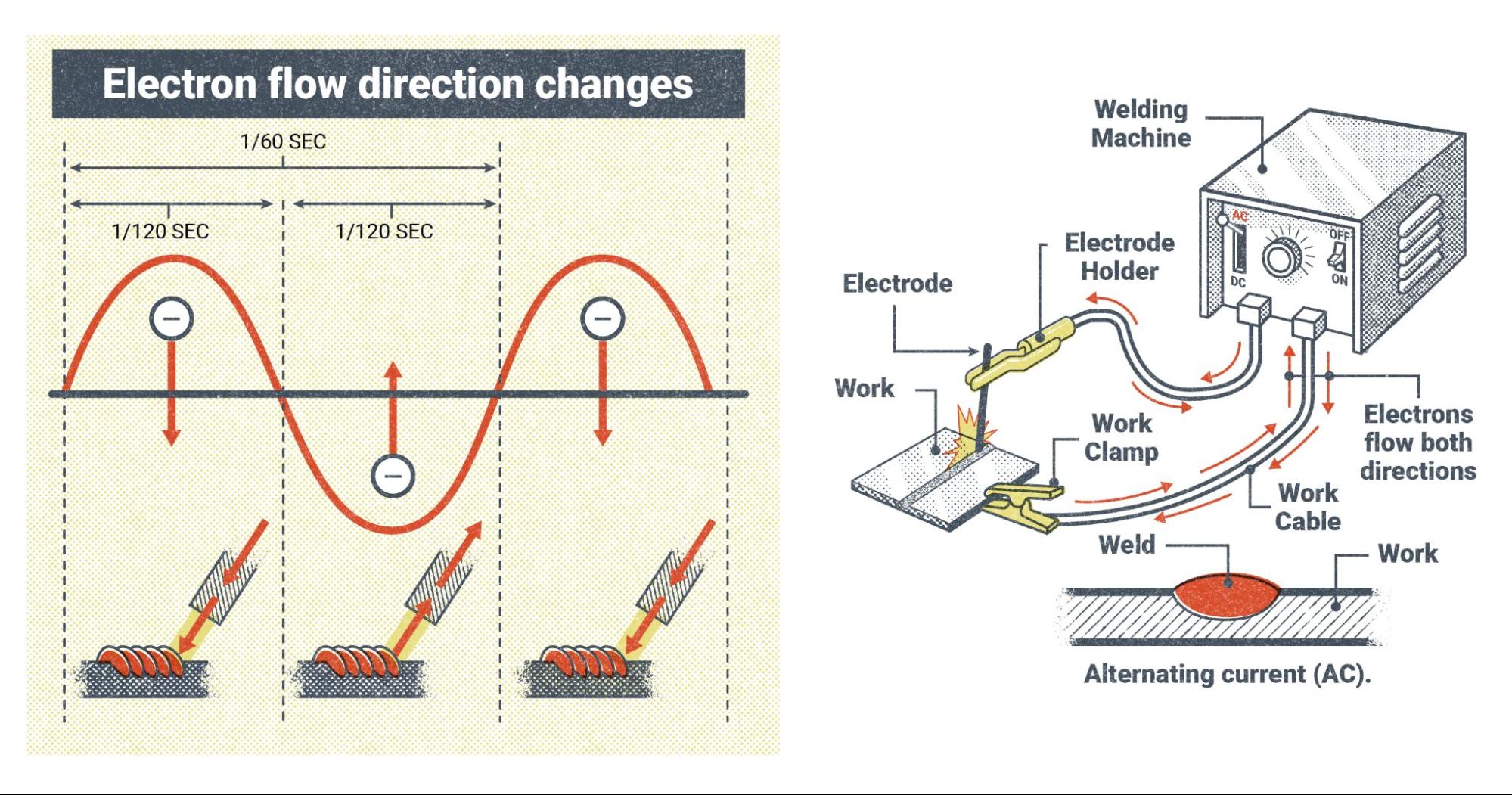
If the welder has the capability to run on alternating current (AC), it won’t matter which terminal the leads are connected to because the machine will automatically change the polarity 120 times per second.
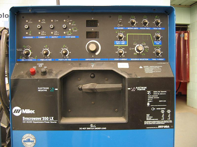
Some welding machines don’t have the option for you to change where the leads are connected. Instead, there will be a switch or a knob that will allow you to select which welding polarity you want.
The electrode holder and work clamp will be attached to the electrode lead and work lead respectively. At this point, you should be able to turn the machine on and proceed to the next step in setting up for SMAW.
SMAW Controls and Settings
Once you have turned the power on, you will need to determine your settings via the controls on the welder. With SMAW, you will likely only have between one and four different controls. The first to adjust, if the machine is equipped with one, would be the polarity selector. The next and most important control is your amperage setting. We will discuss specific amperage settings later in this chapter; for now, it is enough to say that amperage is the primary control for adjusting how the welder runs during welding, and this setting will have the most effect on how your weld turns out. Your machine may have no other controls, but it will always have an amperage control.
The last two controls do not appear on every welder. The first of these is the arc-control setting, which we’ll cover later in this chapter. The purpose of this setting is to make minor changes in how the welding arc behaves, which could make certain welding situations easier to manage. The other possible control is the hot start function, which helps start the arc at the beginning of the weld. The SMAW process is notorious for being difficult to start the welding arc, so this setting could help.
One thing to note about SMAW controls and settings is that you should never adjust them while you are actively welding, as this may damage the machine. Making adjustments while the machine is on is alright, though. Also, if you are using a multi-process machine to weld you may see additional control options. When the machine is set to the SMAW process, most of these controls will be disabled and only the ones mentioned in this section can be used.
Attributions
- Figure 8.4: SMAW accessories by Mgschuler is released under CC BY 3.0
- Figure 8.5: Red Lincoln welding plant and welder working on some steel beams by muygocho is released under CC BY-SA 2.0
- Figure 8.6: Schweißgeraete by EWM AG is released under CC BY-SA 4.0
- Figure 8.7: SMAW Field Shot by Mgschuler is released under CC BY 3.0
- Figure 8.8: Workpiece Lead by David Ridge, for WA Open ProfTech, © SBCTC, CC BY 4.0
- Figure 8.9: Electrode Lead by David Ridge, for WA Open ProfTech, © SBCTC, CC BY 4.0
- Figure 8.10: Arc welding electrodes and electrode holder.triddle by Triddle in the Public Domain; Public Domain dedication, not CC0
- Figure 8.11: Different Electrode Holders by David Ridge, for WA Open ProfTech, © SBCTC, CC BY 4.0
- Figure 8.12: L21-30 plug and receptacle by tholme is released under CC BY-SA 3.0
- Figure 8.13: SMAW DC Setup by Nicholas Malara, for WA Open ProfTech, © SBCTC, CC BY 4.0
- Figure 8.14: SMAW AC Setup by Nicholas Malara, for WA Open ProfTech, © SBCTC, CC BY 4.0
- Figure 8.15: Welding power supply-Miller-Syncrowave350LX-front-triddle by Triddle in the Public Domain; Public Domain dedication, not CC0
A welding power source is a machine that is specially designed to output the specific type of electrical power needed for welding. They can be plugged into an electrical outlet or engine driven. The primary mechanism for producing the welding power can be a transformer, an inverter, a generator, or an alternator.
The workpiece lead is the cable that connects the welding machine to the work clamp.
Welding leads are electrical cables made of many strands of copper wire wound together. The copper wire is sheathed in a durable rubber insulator. Welding leads come in a number of diameters called gauges which are meant to handle different amounts of amperage.
An electrode holder is a device designed to hold and conduct electricity to the electrode. It is designed to be durable and resist the heat of welding, as well as allow the welder to hold it without coming in contact with any live electrical components. Often called a stinger or a torch.
Deoxidizers are chemical elements (such as silicon) added to filler metals and fluxes for the purpose of removing contaminants (such as sulfur and phosphorus) from the molten weld pool during welding.
The American Welding Society is a non-profit organization established for the purpose of “Advancing the science, technology, and application of welding and allied joining and cutting processes worldwide, including brazing, soldering and thermal spraying.” (ref. https://www.aws.org/about/page/home)
Alternating current (AC) is an electric current that is constantly changing polarity, from direct current electrode positive to direct current electrode negative, many times per second. In North America this change happens at 60 Hertz, or 60 cycles per second.
