9.2 FCAW Equipment and Setup
Cameron Kjeldgaard
Components
FCAW is a semiautomatic process, which has an impact on the complexity of the equipment involved. With welding processes that are considered manual, the equipment is usually solid-state; that is, there are no moving parts. In contrast, FCAW always involves a mechanical wire-feeding unit that feeds the electrode into the weld pool with the touch of a button (or, more typically, a trigger), which sharply increases productivity and reduces the required operator skill. The trade-off is a higher initial investment in the equipment and a more in-depth troubleshooting process to solve welding issues.
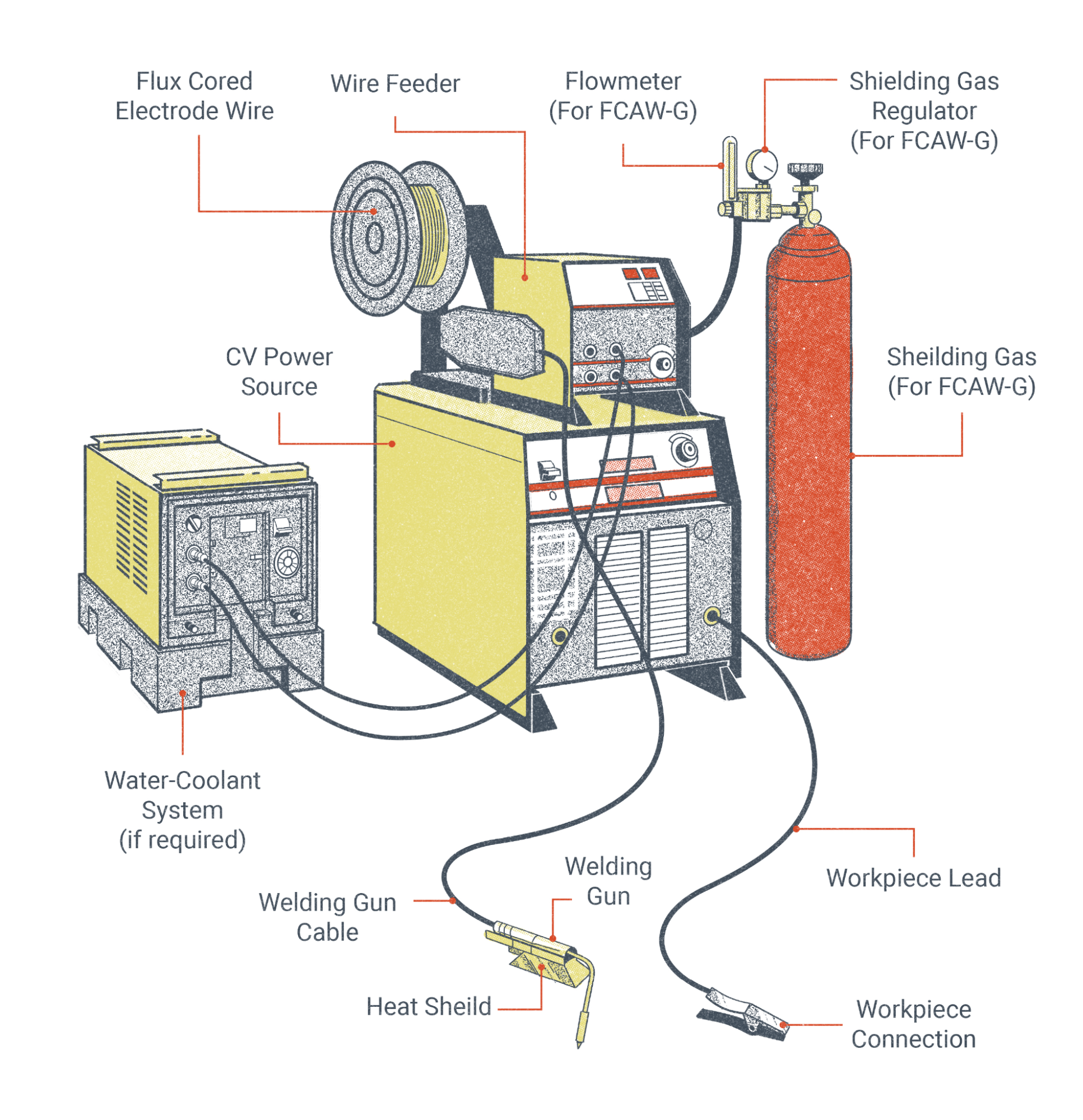
The major components necessary for the FCAW process include:
- Welding power source
- Welding gun and cable
- Workpiece lead and clamp (ground cable/clamp)
- Wire feeder
- External shielding gas (needed for FCAW-G but not FCAW-S)
- Flux-cored wire electrode
The rest of this section explores these components in depth, with the exception of electrodes and shielding gas, which have their own devoted sections.
Welding Power Source
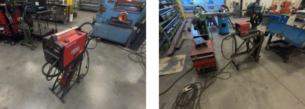
Welding power sources for FCAW may come in the form of transformer rectifiers, though inverter machines—which are capable of multiple welding processes—are becoming the mainstay of the modern welding industry. These welding machines may range in size from compact light-duty units, with the wire feeder and power source integrated into one unit, to large engine-driven welder generators. In industrial applications, an FCAW power source will typically be heavy duty, capable of operating at 100% duty cycle at currents of up to 400 amps or more.
Power sources for FCAW must be capable of producing constant voltage (CV) output, sometimes referred to as constant potential (CP). CV machines produce a volt-amp curve that is nearly flat as opposed to constant current (CC), which produces a steeply sloped volt-amp curve. What this means for you, the welder, is that the welding arc will have small voltage changes and drastic amperage changes depending on your electrode extension. Also, unlike CC, CV processes do not give the welder direct control over welding amperage; instead, the welding voltage is controlled directly at the power source while the amperage is dependent on the wire feed speed and electrode diameter. These three things—voltage, wire feed speed, and electrode diameter—must all be selected in conjunction with each other for a smooth welding operation. It should be noted that many modern welding machines are capable of producing either a CV or CC output, so you won’t necessarily be using or avoiding specific machines. Note that alternating current (AC) should not be used with wire-fed processes like FCAW.
When selecting the polarity at the power source, it is important to check the recommended welding parameters for whatever electrode you will be using. While some of the most commonly used FCAW electrodes for steel operate on direct current electrode positive (DCEP), many are designed to run on direct current electrode negative (DCEN).
Welding Gun and Cable
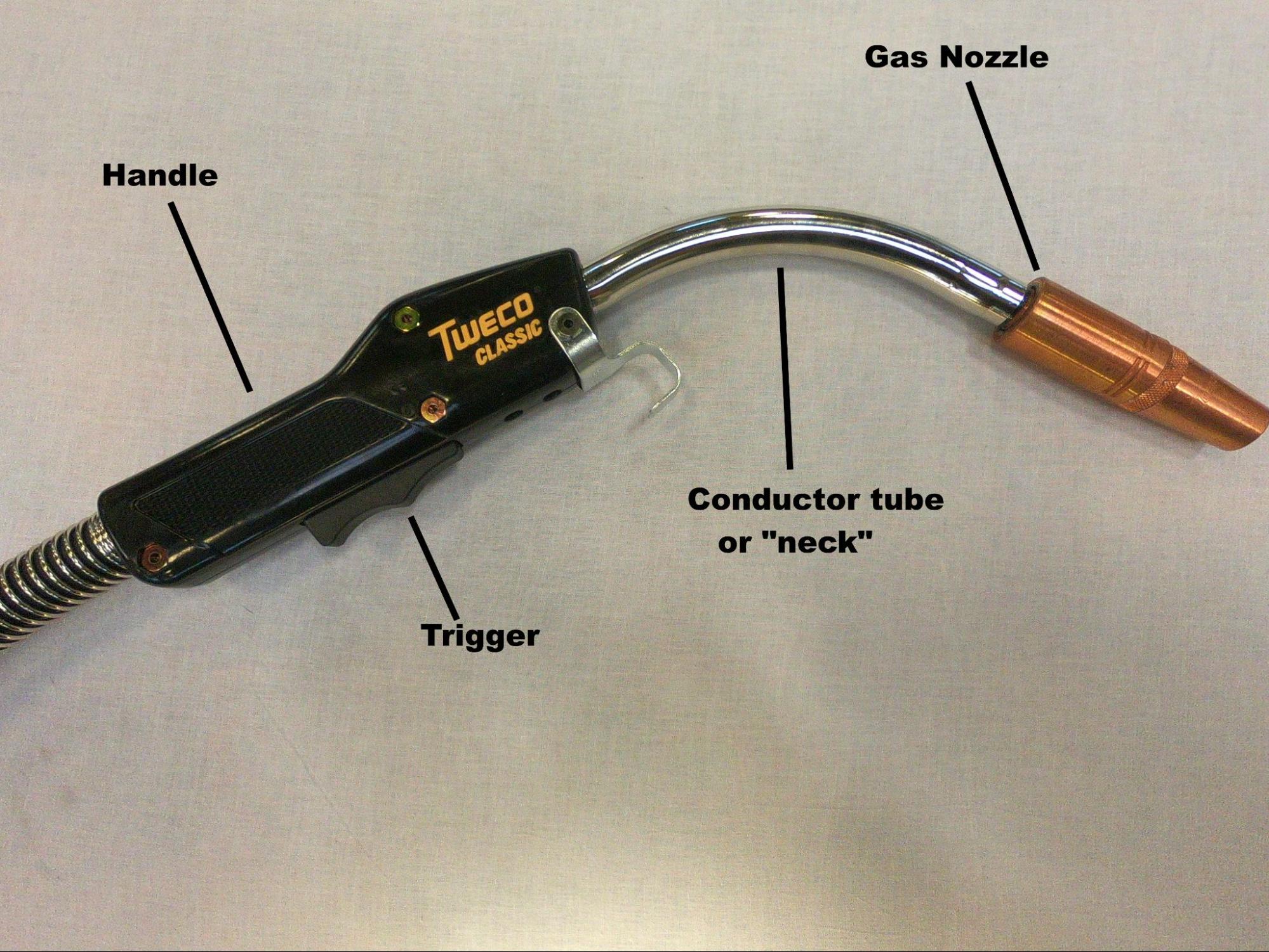
Welding guns, informally referred to as torches or whips, come in a number of configurations from many manufacturers. The primary function of the gun and cable is to conduct the electrode, shielding gas, and welding current from the wire feeding unit to the weld pool. The welding gun insulates the welder’s hand from the welding current and allows them to direct and manipulate the wire electrode. It is especially worth discussing the different parts of the welding gun, as many items are consumable and must be replaced as they wear out.
The handle is typically a heavy-duty plastic that is non-conductive and heat-resistant and serves to insulate the welder’s hands from electrical shock. A trigger, when activated by the welder, will send a signal to the wire feeder to push the electrode and complete the welding circuit. Handles for FCAW-S often have a metal heat-shield to further protect the welder’s hand. If the handle has technical problems, it should be serviced by a qualified technician.
The conductor tube, often simply called the neck, is a piece that screws into the handle. This tube conducts power, electrode, and shielding gas past the handle. Curved conductor tubes of various angles are usually used in semiautomatic applications, and it is more common to see straight conductor tubes in mechanized operations. Flexible conductor tubes and length extensions are also available. The tube must be replaced when it becomes worn, but with proper care it can have a very long service life.
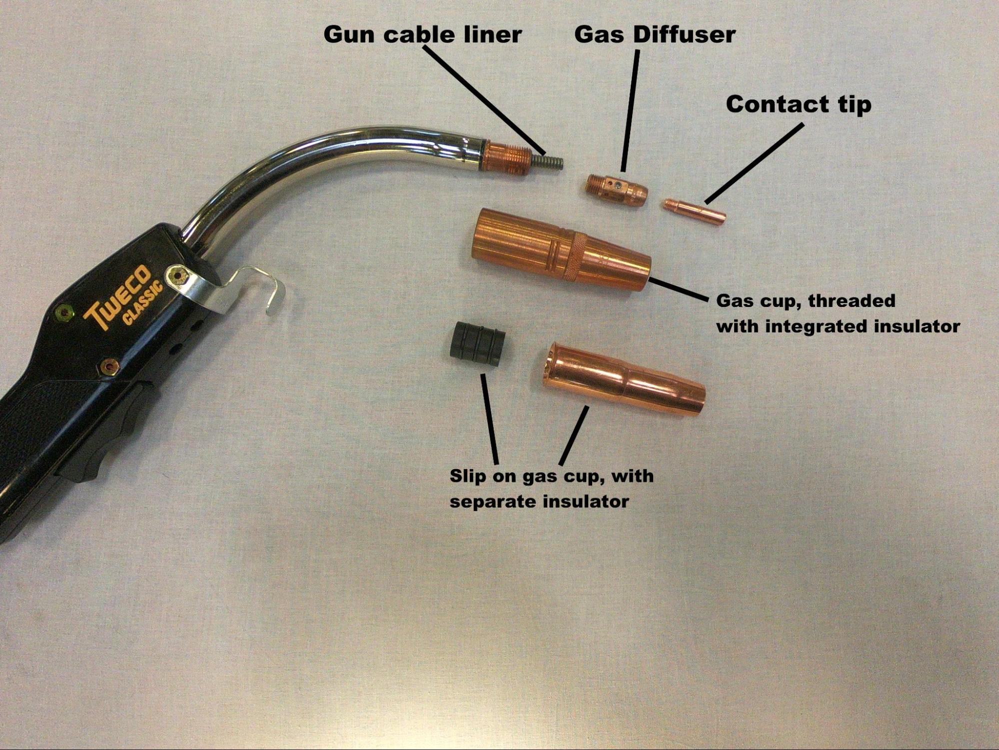
A gas diffuser, a consumable item, attaches to the conductor tube. Diffusers have a series of evenly spaced holes that distribute shielding gas evenly as it leaves the conductor tube. If you encounter porosity, the holes in the diffuser may have become clogged or misshapen. The diffuser also typically conducts power to the contact tip.
The contact tip is where the wire electrode becomes electrified. Contact tips are simply copper cylinders with holes through the center. The hole is sized according to the electrode diameter and must fit well to provide a good electrical connection. Over time, as the tip is heated and cooled repeatedly, the hole may become misshapen and prevent smooth wire feeding. A worn tip may be to blame if wire is not feeding or if the feeding is irregular.
The gas nozzle, or gas cup, directs the shielding gas towards the weld area. The nozzle acts like a shroud, covering the contact tip and gas diffuser. The nozzle must also be insulated from the welding circuit. The insulator, usually ceramic but always non-conductive, may be a separate piece that screws onto the conductor tube just below the gas diffuser, but many gas nozzles have integrated insulators. If the insulator fails, an electrical arc can jump between the base metal and gas nozzle, causing arc strikes. The nozzle should be cleaned regularly, as it will fill up with weld spatter. A pair of “welpers” or MIG pliers are useful for getting the job done. If the nozzle fills up with too much spatter, the flow of shielding gas will be impeded (causing porosity) or the gas nozzle may become electrified (causing arc strikes).
Like many components in the welding system, the welding gun will have an amperage rating. If the welding current exceeds the amperage rating of the gun, it will become overheated and rapidly deteriorate. Guns rated up to 400 amps are typically gas-cooled, meaning the flow of shielding gas through the gun is sufficient to keep it cool. Welding guns with higher amperage ratings tend to be liquid-cooled, such that coolant is circulated through the gun as it is operated. It is important to make sure coolant is present in the system and the coolant pump is running before operating those guns.
The cable of the welding gun contains a power cable to transmit the welding current, a gas line for shielding gas, and a liner through which the wire electrode is pushed. In the case of liquid-cooled torches, there will also be coolant-out and coolant-return lines. Of all the lines within the cable, there is one that you, the welder, may be expected to service: the cable liner the electrode moves through. As the wire is fed through the liner, it often introduces dust and debris to the liner and, over time, this will cause wire feeding issues. This can be prevented by installing cleaning and lubricating pads over the wire at the wire feeder, though the cable liner will still need to be cleaned and possibly replaced after a long enough time.
There is another way in which the cable can lead to wire feeding issues. If, at any time during welding, you are experiencing erratic wire feeding, take a look at the cable. Does it have numerous sharp twists and turns in it? If so, this may be the source of the problem. Every tight turn in the gun cable makes it that much more difficult for the wire feeder to move the wire through the gun cable liner. Keep any curves in the cable large and gentle.
Workpiece Lead and Clamp
The workpiece lead and clamp, often collectively referred to as the ground clamp, connect the work to the welding circuit. Both the lead (cable) and clamp have amperage ratings, just as with the welding gun. If this rating is exceeded, the components will rapidly heat up and deteriorate.
FCAW is a welding process that uses direct current (DC) electricity. These processes are susceptible to arc blow, which is an unstable welding arc caused by the strong magnetic force produced by the welding circuit. Arc blow can be a difficult issue to solve; however, moving the workpiece clamp to a different location will often be enough to help minimize or eliminate it. Additionally, slowing the wire feed rate will result in a lower welding amperage, which may also be helpful for this issue.
Wire-Feeding Unit
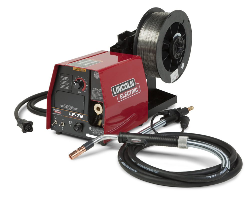
Wire feeders, which are really wire-feeding systems, can come in a number of different configurations. In industry, it is most common to see wire feeders as separate machines that are connected to the welding power source. The electrode lead will run from the negative or positive terminal on the welder to a power block inside the wire feeder, which will provide electricity for both the motor in the wire feeder and the welding circuit itself. Shielding gas, if necessary, will also be piped in from the cylinder or gas system to a connection in the wire feeder. The coil of wire electrode typically mounts to a spindle on the wire feeder and passes through a set (or sets) of drive rolls that push (and in some cases pull) the electrode through the gun cable, along with the shielding gas and electricity of the welding circuit.
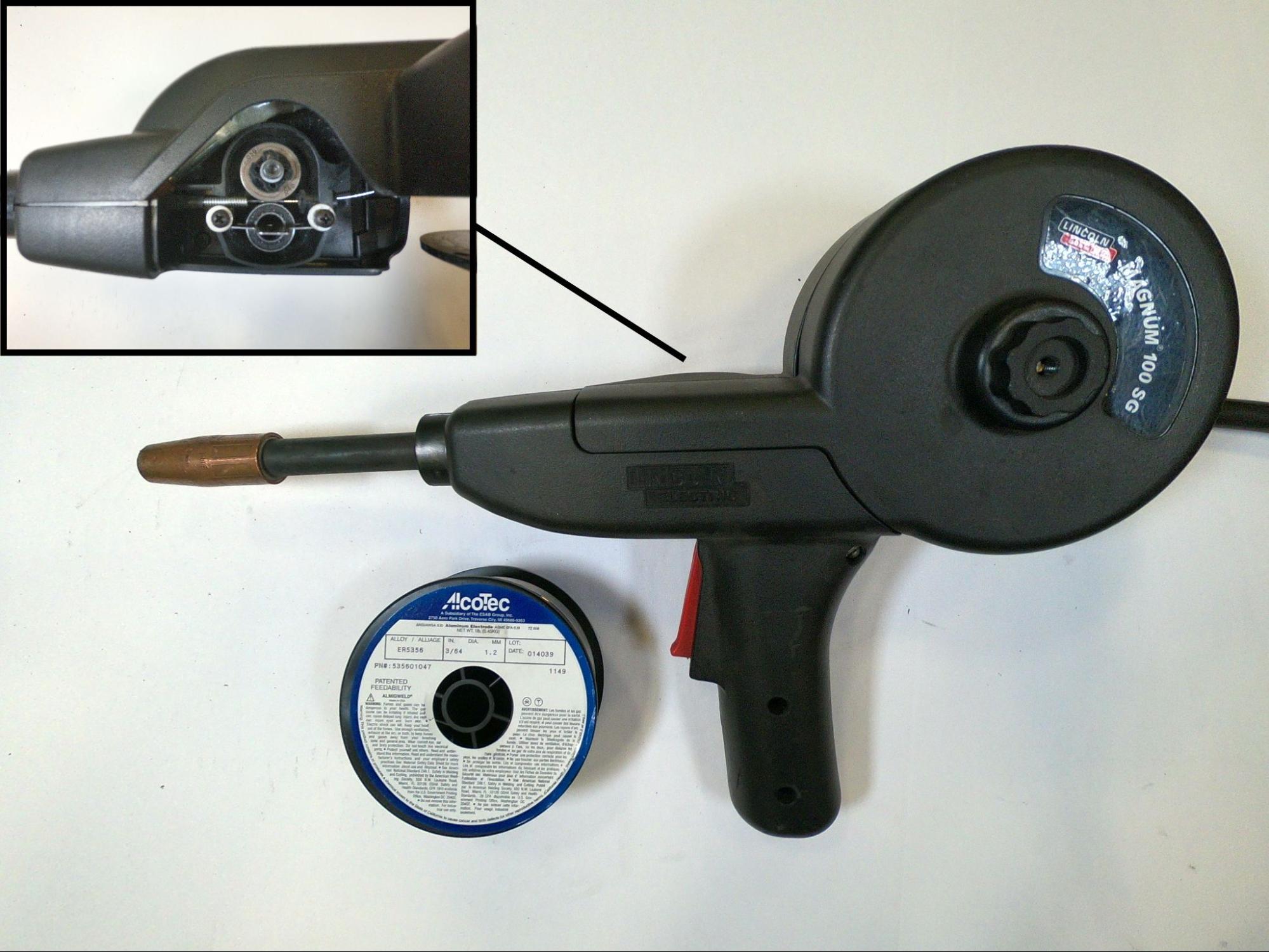
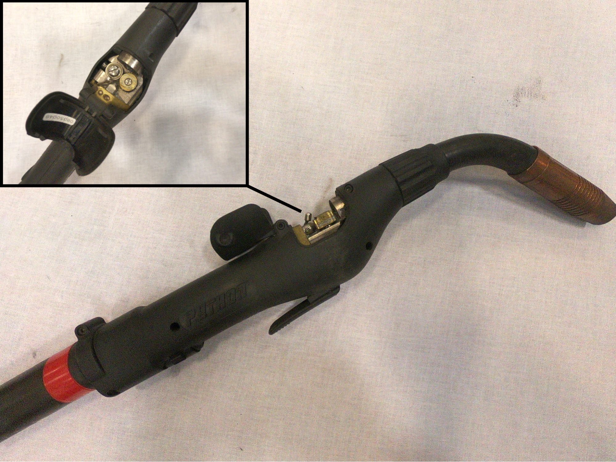
Although what was just described is the most common wire-feeding system, that is not the only way they may be encountered. Smaller welding power sources, meant for hobbyists or light-duty work, may have the welding machine and wire feeder integrated into one unit. In the case of push-pull systems, part of the wire-feeding system is integrated into the welding gun. In the case of spool guns, the entire wire-feeding system is integrated into the welding gun itself.
The primary function of the wire-feeding system is to feed the long coil of wire electrode to the welding area where it is melted off, transferred to the weld puddle, and then solidified into weld metal. The simplest and most common wire feeding system is a push-pull system. In this system a pair (or pairs) of motorized drive rolls, driven by an electric motor in the feeder, pull the coiled wire electrode off the spool and push it through the gun cable, which is activated by the trigger on the welding gun.
Wire feeders are complex machines, so if any serious repair is required a qualified technician should service the machine. However, there are parts that must be changed out, replaced, or adjusted on a routine basis, and it is a common expectation that the welders themselves will be able to recognize and service these items. Let’s cover some of those parts.
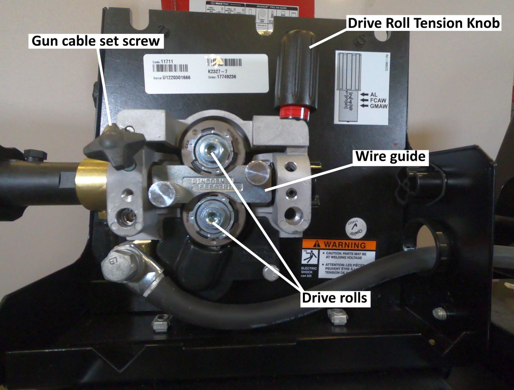
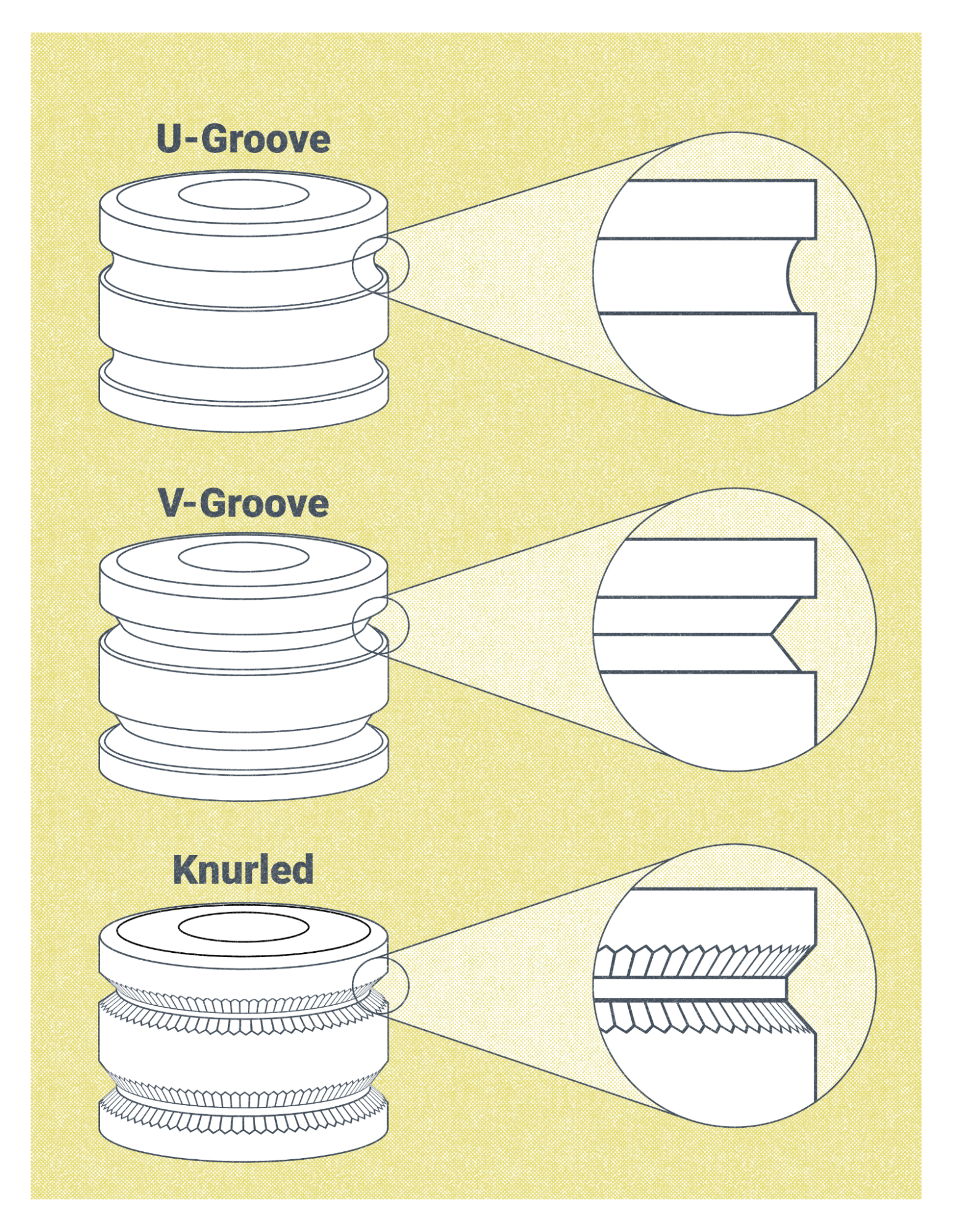
- Drive rolls are a pair of wheels with specifically sized grooves, and the wire electrode fits inside the grooves and is squeezed. The drive rolls are turned by a variable-speed motor, pushing the electrode through the gun cable. Their size corresponds with being designed to work with a specific diameter of electrode. Additionally, there are several types of grooves that drive rolls may have:
-
- V groove drive rolls are commonly used for steel electrodes, which have a solid composition
- U groove drive rolls are used with solid wire electrodes that are soft, like aluminum, and may be deformed if squeezed between V groove drive rolls. If the wire is deformed or squished out of its round shape, it makes it difficult or impossible to feed it through the gun cable and contact tip.
- Knurled drive rolls have small teeth in the grooves. This allows the drive rolls to grip and push the electrode without applying too much pressure. These rolls are used for FCAW, as those electrodes are not solid, but consist of a tubular sheath filled with flux.
- The drive roll tension knob adjusts the pressure the drive rolls squeeze the electrode with. Too much tension deforms or damages the wire, leading to inconsistent feeding and introducing debris into the gun cable, while too little tension will cause the drive rolls to slip rather than push the wire.
- The wire guide ensures the wire accurately passes through the groove in the drive rolls. The wire feeder pictured in Figure 9.10 has a single guide that fits over the drive rolls. Other feeders may have two guides, one on the inlet and another on the outlet side of the drive rolls. Like drive rolls, wire guides are designed to work only with specific electrode diameters. Accordingly, a given electrode diameter must be used only with matching drive rolls and guides.
- The gun cable set screw secures the gun cable into a bushing in the wire feeder. This gun cable receiver bushing is where the electrode, power, and shielding gas enter the gun cable. This screw must be tightened securely to prevent the gun cable from working its way out of the wire feeder.
A push system is the simplest, most economical wire-feeding system and is the one most commonly employed for FCAW. Spool guns and push-pull systems are used when needed to feed particularly soft electrodes (like aluminum) or for very small diameter electrodes (0.023 inch and smaller), which have a high likelihood of bird-nesting, a phenomenon that occurs when the wire electrode folds over the top of itself rather than smoothly traveling through the gun cable. This results in a tangle of wire balling up near the drive rolls and must be removed before welding can continue.
Since FCAW is mostly used for welding thicker sections of steel, the process requires wire electrodes large and stiff enough to be fed with a push system. To ensure consistent wire feeding, a couple of things must be taken into consideration. First, the length of the gun cable should not be excessive. The longer the cable, the harder the wire feeder has to work; a 10-foot to 12-foot gun cable is common for most applications. Second, care should be taken to keep the gun cable straight, free of sharp twists and turns. This is relevant because the straighter the gun cable, the easier it is for the wire feeder to successfully push the electrode through the length of the gun cable.
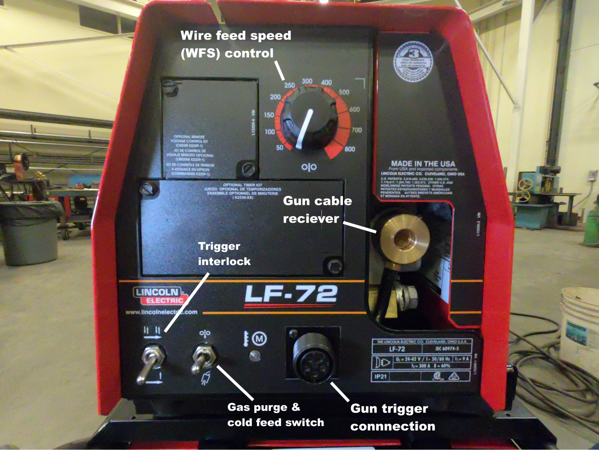
There are many adjustments and settings on modern wire feeders. Some of these, like wire feed speed, are essential variables to the welding process. Others, like trigger interlock, make the work easier and increase operator appeal.
- Wire feed speed (WFS) is controlled by a knob that adjusts the voltage sent to the motor, which turns the drive rolls. In the U.S., wire speed is measured in inches per minute (IPM). On the wire feeder shown in Figure 9.12, the knob has a scale in IPM, but this is not always the case. Use this method to accurately determine wire speed: trim the wire flush with the gas nozzle, use a stopwatch to feed wire for exactly 15 seconds, then measure how many inches of wire fed out of the gun in that time, and multiply that by four. This will calculate the inches of wire fed per minute. WFS, in conjunction with the electrode diameter, determine the appropriate welding current or amperage.
- A gas purge and cold feed switch is common on most modern wire feeders. These are items of convenience. Cold feed, sometimes called jog, feeds wire without electrifying the welding circuit. It is helpful when fitting the machine with a new spool of electrode. The gas purge button pushes shielding gas through the system without feeding wire; it is used when adjusting gas flow rates or troubleshooting shielding gas problems.
- The trigger interlock switch changes how the gun trigger functions. Without trigger interlock, the gun trigger must be constantly held in place to continuously feed wire. With trigger interlock in place, the gun trigger functions with a toggle, the welder need only pull the trigger once to begin feeding wire and once again to stop the feeding. Trigger interlock can help reduce fatigue for your hands when making especially long welds.
- The gun cable receiver is a bushing where the gun cable attaches to the wire feeder and receives the electrode, power, and shielding gas.
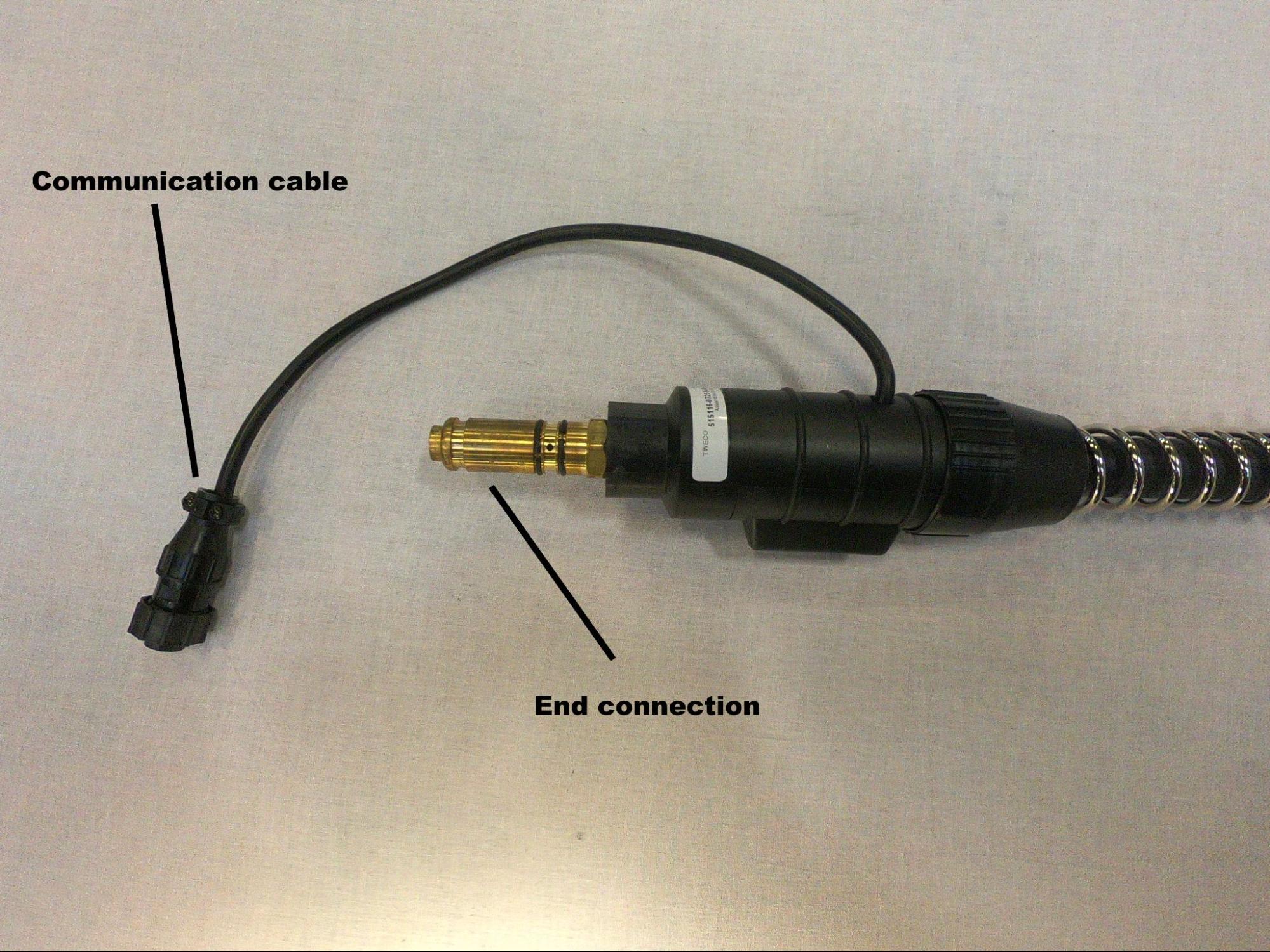
- The gun trigger connection is where a communication cable connects from the gun cable to the feeder. This allows the gun trigger to communicate with switches inside the feeder, which control the drive rolls, power, and shielding gas flow. On some feeders, this cable can easily come unplugged and is a good first inspection point if the wire feeder seems to stop working suddenly.
Setting Up the Welding System
The first step in setting up any arc welding system is getting power to the welding power source. This is as simple as plugging in the machine, but the circuit must have the proper voltage and amperage. Light- and medium-duty machines may plug into 110-volt or 220-volt circuits, respectively, and 20 or 30 amps on the circuit are common. Do not take these numbers at face value, though; the required electrical input for any welding machine will be specified by the manufacturer and listed on the machine itself or the owner’s manual. Heavy-duty machines commonly require a 480-volt, 50-amp circuit. These types of circuits have what is called three-phase power, a type of electrical power that is not typical to a home or outside of industrial environments.
Once power is supplied, the machine should be set up to run DCEP polarity . A properly sized power cable should be connected from the positive terminal of the machine to a terminal inside the wire feeding unit. The workpiece lead and clamp should be connected to the negative terminal of the welding machine. DCEP is overwhelmingly the norm for FCAW, but there are a few wire electrodes that should be used with DCEN; in any case, always follow the electrode manufacturer’s recommendations
The next step is to turn your attention to the wire feeder. If you’ll be using FCAW-G, you will need a supply of external shielding gas to protect the molten weld puddle from atmospheric gasses properly. A cylinder of the proper shielding gas should be fitted with a regulator and flow meter. From the flow meter, a gas line is connected and run to a shielding gas inlet, usually located on the back of the wire feeder. The type of shielding gas used will depend on the material being welded. In this and all other cases, the high pressure cylinder of shielding gas should be anchored to the welding cart of a wall by a chain to prevent it from falling. If using FCAW-S, shielding gas is not required.
Then the wire feeder must be fitted with the proper drive rolls, wire inlet, and outlet guides. When installing these components, the diameter of the wire electrode must be considered, as these parts are made to accommodate specific wire sizes.
Next, the spool of wire electrode can be put on. The spool must be oriented so that the end of the wire rolls off the spool from the bottom. It is critical that once the end of the wire is freed from the spool frame you do not let go of it. If you do, the spool of wire will uncoil and create a huge mess, and it can be difficult or impossible to salvage the spool if this happens. Keeping hold of the wire, pass it through the inlet hole on the back of the feeder housing, then feed it through the wire guides and drive rolls, clamping the drive rolls onto the wire and securing them in place with the tension knob. Once the wire is clamped in the drive rolls there is no danger the spool will uncoil.
The wire can then be fed through the gun cable using the gun trigger or cold feed switch. When feeding new wire through the gun cable, the gas nozzle and contact tip should first be removed from the gun, as the wire can get hung up on the contact tip—but be sure to reinstall them once you are done. The gun cable should also be kept as straight as possible while you perform this step to ease the feeding of the wire.
With this completed, the system is ready to weld. Connect the workpiece clamp to the welding machine, and you can get to welding!
Attributions
- Figure 9.3: Major Pieces Of Equipment Used In The FCAW Process by Nicholas Malara, for WA Open ProfTech, © SBCTC, CC BY 4.0
- Figure 9.4: Two FCAW Welding Systems by Cameron Kjeldgaard, for WA Open ProfTech, © SBCTC, CC BY 4.0
- Figure 9.5: Assembled Welding Gun by Cameron Kjeldgaard, for WA Open ProfTech, © SBCTC, CC BY 4.0
- Figure 9.6: Disassembled Welding Gun and Consumables by Cameron Kjeldgaard, for WA Open ProfTech, © SBCTC, CC BY 4.0
- Figure 9.7: FCAW Wire Feeder by Mgschuler is released under CC BY 3.0
- Figure 9.8: Spool Gun by Cameron Kjeldgaard, for WA Open ProfTech, © SBCTC, CC BY 4.0
- Figure 9.9: Push-Pull Welding Gun by Cameron Kjeldgaard, for WA Open ProfTech, © SBCTC, CC BY 4.0
- Figure 9.10: Wire Feeder, Interior by Cameron Kjeldgaard, for WA Open ProfTech, © SBCTC, CC BY 4.0
- Figure 9.11: Drive Rolls Used In Welding Wire Feeders by Nicholas Malara, for WA Open ProfTech, © SBCTC, CC BY 4.0
- Figure 9.12: Wire Feeder, Front by Cameron Kjeldgaard, for WA Open ProfTech, © SBCTC, CC BY 4.0
- Figure 9.13: Gun Cable End by Cameron Kjeldgaard, for WA Open ProfTech, © SBCTC, CC BY 4.0
Constant voltage is a form of welding welding power in which the voltage is set on the welding machine. The machine then tries to maintain a specific voltage and therefore a specific arc length during welding. The amperage is automatically adjusted by the welding machine based on the wire-feed speed and the distance of the welding gun to the workpiece. Constant voltage is used with semi-automatic welding processes like GMAW and FCAW.
A chart which displays the relationship of the machines output voltage and amperage at different arc lengths, or lengths of electrical stickout.
