9.3 FCAW Electrodes and Shielding Gas
Cameron Kjeldgaard
Electrode Classification
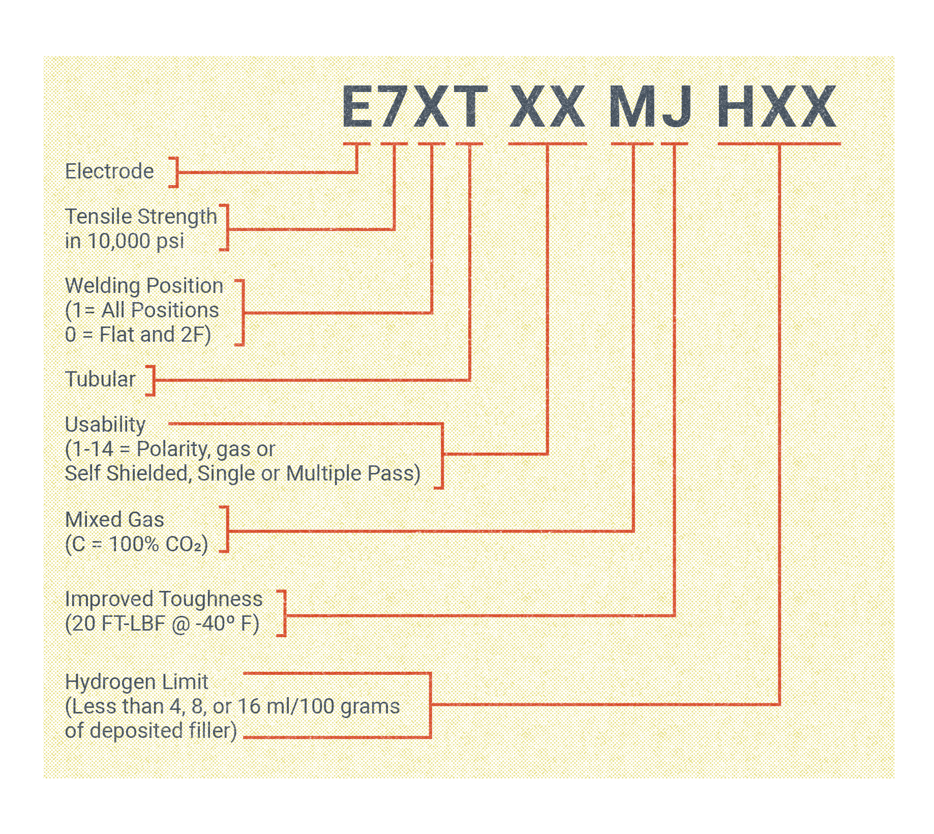
Figure 9.14 shows the FCAW electrode classification system, developed by the AWS, that is used for carbon steels and low-alloy steels. They are the metals most commonly joined with FCAW. The requirements for these electrodes are specified in the AWS standards A5.20 and A5.29, respectively.
To interpret this carbon steel and low-alloy steel electrode classification, let’s explore the significance of each character from left to right:
- The letter E is for electrode.
- The number in the next position denotes tensile strength in tens of thousands of psi. For example, a 7 would signify a tensile strength of 70,000 psi.
- The unit in the third position designates the welding position. A 1 indicates the electrode is suitable for all welding positions and a 0 means the electrode should only be used in the flat and horizontal position.
- The T denotes the electrode’s tubular construction.
- The space following the dash may have any number between 1 and 14. This number indicates the electrode’s usability, which refers to several characteristics: the required polarity, if it is self-shielded or gas-shielded, and if it is suitable for single- or multi-pass welds.
- Next is the gas type indicator. An M in this position means a mixed-gas blend should be used. A C means pure CO2 shielding gas is needed.
- What follows is an optional suffix. If a J in this position is present, it means the electrode meets the requirements of improved impact toughness testing.
- Another optional suffix will only appear if the electrode has low-hydrogen requirements. The three characters HXX are used for low-hydrogen electrodes. H4, H8, or H16 indicate the electrode has less than 4 milliliters, 8 milliliters, or 16 milliliters per 100 grams of deposited weld metal, respectively.
FCAW can also be used to weld several other metals, including stainless steels, cast irons, and nickel alloys, and FCAW is also used in various surfacing applications, such as hardfacing. The classification for the electrodes used for welding those materials have some similarity to the one discussed above, but each electrode classification system is unique and has specific suffixes and prefixes. The AWS has created filler metal specifications for each material and welding process. If using FCAW to weld these metals, be sure to understand the electrode classification system in order to select the proper electrode.
FCAW Electrodes
FCAW electrodes have a tubular construction. They consist of a metal sheath, which is typically chemically similar to the base metal, filled with a powdered flux. The flux consists of various powdered metals and other elements. The flux serves a variety of purposes:
- Shielding: Some flux elements will vaporize into a shielding gas in the heat of the welding arc.
- Cleaning: Oxygen and nitrogen are common impurities present in base metal. Elements like aluminum, silicon, and manganese present in the flux scavenge these impurities out of the weld.
- Slag formation: Some elements in the flux will form a slag that floats to the top of the weld and solidifies. This slag acts as a blanket, significantly slowing the cooling rate of the weld and improving the finished mechanical properties.
- Arc stabilization: The flux provides easier arc initiation and stabilizes the welding arc. This improves the transfer of metal droplets from the electrode to the weld pool, reducing spatter and increasing electrode efficiency.
- Alloying: Some elements in the flux will alloy themselves into the finished weld metal. This allows electrodes to be tailored to a variety of base metals and meet a wide range of mechanical and chemical requirements.
Some FCAW electrodes are suitable for single-pass welds only and are designed for welding on extremely dirty or contaminated metal. They are very high in the deoxidizing and denitrifying elements mentioned above to accomplish this. Using these in multi-pass welds can result in a build-up of these elements at the intersection of weld beads when they are stacked up. This buildup is extremely detrimental to the mechanical properties of the weld.
If an electrode is classified as meeting low hydrogen requirements (indicated by the presence of the HXX suffix in the classification), there are special packaging and storage considerations. As their name indicates, low-hydrogen electrodes are manufactured and tested to ensure strict limits on the hydrogen content of the finished weld metal. This is critical for steels that are susceptible to hydrogen-assisted cracking (HAC), which is sometimes called underbead cracking. Low-alloy electrodes can be contaminated by hydrogen from ambient moisture in the air. For this reason, they are often packaged in vacuum-sealed bags. In many welding applications there will also be limits on how long the electrode can be out of its packaging and exposed to the atmosphere, usually between 24 to 72 hours. When not in use, the electrode should be stored in an impermeable container like a plastic bag. It may also be stored in an electrode storage oven, which are hot enough to drive away any humidity. In some cases, it is may be acceptable to use an electrode oven to cook the moisture back out of an electrode that has been exposed to open air for too long.
Electrode diameter is of critical importance. FCAW electrodes are commonly available as small as 0.035 inch in diameter all the way up to0.125 inch. A good rule of thumb is that as base metal thickness increases, so should electrode diameter. This rule does not apply at a 1:1 ratio, though; a given diameter of electrode will be able to weld a range of metal thicknesses. But as metal thickness increases, so will the required welding current necessary to achieve good penetration, and larger diameter electrodes can operate better at these higher currents than smaller electrodes.
Another consideration closely tied to electrode diameter is welding position. Larger electrodes, with their higher current requirements, create a large and more liquid weld puddle. This makes larger electrodes more difficult to control and unsuitable for vertical or overhead welding, even if the electrode is classified for all-position welding. In this author’s experience, electrodes larger than 0.0625 inches in diameter are unsuitable outside the flat or horizontal position. The primary advantage of larger electrodes is an increased deposition rate—that is, far more weld metal can be deposited in a given time than with smaller electrodes.
Electrical stickout is also a critical factor in the operation of FCAW electrodes. Sometimes called electrode extension or abbreviated as CTWD (contact tip to work distance), it is the distance the electrode extends past the contact tip before it arcs to the work, where it generates the heat for welding. Earlier in the chapter, we discussed the fairly flat volt-amp curve that constant voltage welding power sources operate on.
The line of the volt-amp curve represents the possible outputs of the welding power source at a given voltage and amperage setting. Where the output of the machine is on that line is directly related to electrical stickout. As electrical stickout increases, welding voltage goes up slightly while welding amperage decreases drastically. The inverse happens when electrical stickout is decreased. Because electrical stickout so dramatically affects welding amperage, it must be carefully controlled for by the welder.
Amounts of electrical stickout are recommended by the electrode manufacturer. For FCAW-G electrodes, this range usually falls between 0.5–1.25 inch, a relatively narrow range. FCAW-S electrodes may have a larger range, from 0.75 inch to as long as 3.5 inches. Besides the need for shielding gas, this electrical stickout discrepancy is the largest difference between gas- and self-shielded electrodes. The reason for this is that some self-shielded electrodes have flux that must be preheated to work properly once they combust in the heat of the welding arc. After the welding circuit leaves the copper contact tip and enters the wire electrode, it experiences much more electrical resistance, which heats the electrode. Both the resistance and heat increase with electrical stickout, accomplishing this preheating effect for FCAW-S electrodes.
Shielding Gasses
FCAW electrodes do not always require a supply of shielding gas, as self-shielded electrodes produce their shielding from the combustion of powdered flux inside the electrode. When using gas-shielded electrodes, however, the shielding gas used can affect the characteristics of the arc and the finished weld.
Probably the most widely employed shielding gasses for FCAW-G is pure carbon dioxide, CO2. It promotes a globular transfer of metal from the electrode to the weld pool, producing an erratic arc with large amounts of weld spatter. It also produces a deep penetration profile. CO2 is also a very efficient gas coolant, meaning as it flows through the welding gun it effectively cools the gun. Despite producing a harsh welding arc, CO2 is widely used because it is the least expensive shielding gas available. It should be noted that CO2 has an endothermic effect when it is depressurized, which means as it leaves the high-pressure gas cylinder it can ice up and freeze gas flow regulators. At flow rates above 25 cubic feet per hour (CFH) a heat source (such as a heat lamp or heater-equipped gas regulator) should be used, especially in winter conditions, to counteract this effect.
Another shielding gas commonly employed in FCAW-G is gas blend of argon and CO2, with about 75–80% of the blend being argon. Argon has a higher ionization potential than CO2. Ionization potential is a reference to how much energy is required to positively charge the shielding gas, therefore allowing it to conduct the welding arc. The introduction of argon into the gas mix results in a much smoother arc with less weld spatter than when using pure CO2, which also increases electrode efficiency and operator appeal. An argon/CO2 blend gas produces a flatter and typically better looking weld bead but makes for a shallower penetration than pure CO2.
While pure CO2 and an argon/CO2 blend are the two shielding gasses used in almost all FCAW-G applications, an occasional exception is a blend of 98% argon and 2% oxygen. It is used when welding some stainless steels.
The shielding gas for any particular electrode will be recommended by the electrode manufacturer, and is indicated by an M or C suffix in the electrode classification. Regardless of the gas selected, the flow rate should be set between 30–45 CFH when welding.
Attributions
- Figure 9.14: SMAW Electrode Classification © American Welding Society, illustration by Nicholas Malara (SBCTC Illustrator) Used with permission from the rights holder, the American Welding Society.
