9.4 FCAW Operation and Welding Techniques
Cameron Kjeldgaard
FCAW Welding Fundamentals
The fundamentals of FCAW are about the same as those for other arc welding processes:
- Electrical characteristics (current, voltage, and polarity)
- Electrical stickout
- Work and travel angle
- Travel speed
- Electrode manipulation
Electrical characteristics will be recommended by the electrode manufacturer and controlled by the welding procedure specification. The required polarity for an electrode must be used, but welding current and voltage will be recommended as a range and there is room for adjustment. Where you set the machine within this range is really a function of base metal thickness: Thicker base metals will require higher electrical settings, which increase the heat of the welding arc. Remember, there is no direct way to control welding amperage. Rather, amperage is determined by wire feed speed and electrode diameter, with larger electrodes and higher speeds resulting in high welding amperage. At all times you should remain within the range recommended by the manufacturer or required by the welding procedure.
As we’ve already covered, it is critical that the proper stickout is maintained as the electrode is moved down the joint. This takes practice to get used to, so don’t get discouraged. Keeping your head in a good position is helpful in maintaining proper stickout—if your head is positioned directly behind, or nearly behind, the welding gun, it is difficult or impossible to see the amount of stickout. Instead, find a comfortable position where your head can be on one side of the welding gun and you can see, and therefore monitor, the amount of electrical stickout during welding.
The work and travel angles of the electrode influence where the heat of the arc is directed and the shape of the finished weld bead. Electrode angles are not controlled for in welding procedures and are left up to the discretion of the welder. Selecting the proper angle and maintaining it throughout welding is a practiced skill.
Travel angle is the angle of the electrode relative to the length of the weld joint. Guidance for the travel angle in FCAW is rather straightforward: a pulling or dragging angle of 10–30 degrees should be used. A common saying among welders engaged in welding processes that produce slag is “if there’s slag, you drag”, as it speaks to a problem with pushing these types of electrodes. If FCAW electrodes are pushed along the joint, there is a strong chance a ball of slag will be pushed in front of the weld puddle resulting in a slag inclusion at the root of the weld bead. The one notable exception to this rule is when welding in the vertical position with an upward progression—in this case, a slight push angle of 10–15 degrees should be used.
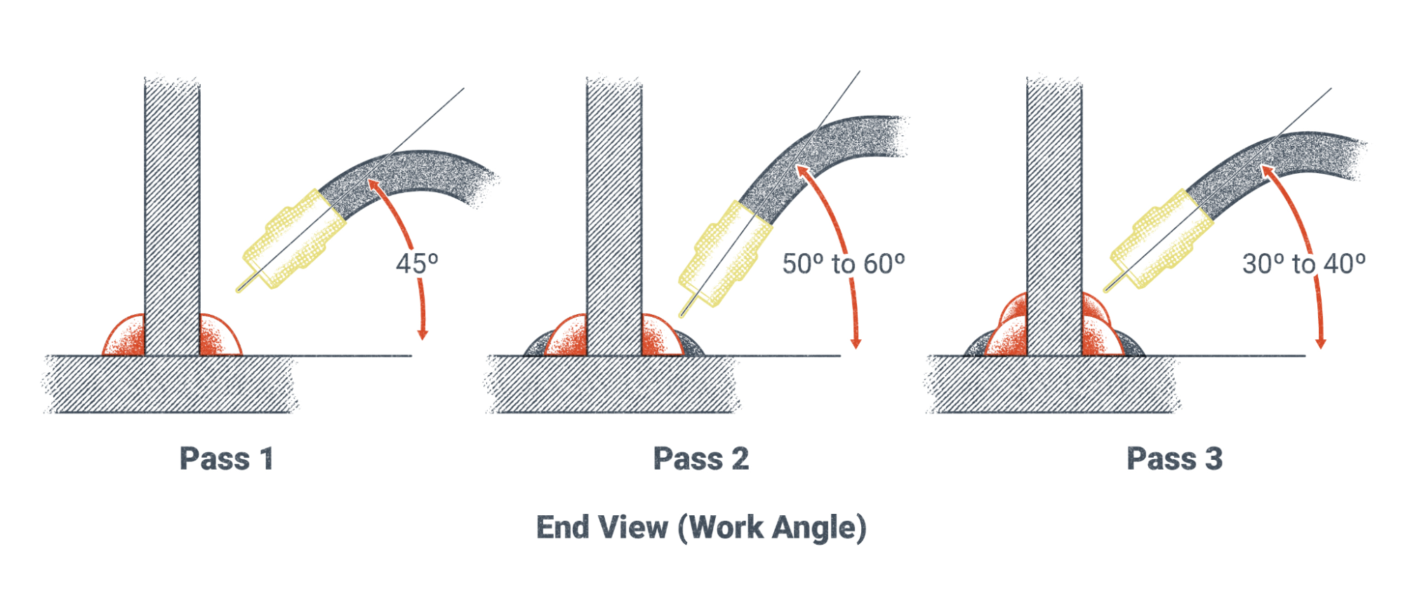
Work angle, the angle of the electrode relative to a cross section of the joint, is a more complicated matter. The exact work angle used in FCAW is a matter of how the joint is designed and where the welder would like to direct the heat of the arc and deposited weld metal. In multi-pass welds the work angle of each weld pass may be different in order to properly fuse each pass and achieve the correct weld size. Take the example below of a three-pass fillet weld in a T joint:
- A 45-degree work angle is used in the first pass to direct the heat and weld metal straight into the joint root.
- In the second pass, a higher work angle of 60-degree is used to ensure proper fusion to the weld bead and base metal below.
- For the third pass, a lower work angle of about 30-degree is used to help push the weld deposit upward and give the vertical leg of the weld its proper height.
Travel speed, another fundamental of FCAW, is the speed the electrode progresses along the joint. Travel speed in FCAW, as well as GMAW, is significantly faster than SMAW or GTAW processes. This can present a challenge for welders when they are learning the process. Too slow a travel speed can result in overlap and an overly convex weld. Too fast a travel speed can leave undercut, lack of proper fusion, and an undersized weld. Travel speed is an essential variable recommended by the manufacturer and controlled by the welding procedure specification (WPS). The proper travel speed for FCAW electrodes typically ranges from 8–12 inches per minute, but you should always consult the electrode manufacturer’s recommendations or the proper WPS to ensure successful welding.
Finally, electrode manipulation can be used to increase the size or width of an individual weld bead and can be helpful in controlling the heat of the welding puddle. Because FCAW has a high deposition rate and large-diameter electrodes are available, a stringer bead is often sufficient, especially in the flat position. However, when welding with a smaller electrode or in any position other than flat, a weaving technique can be favorable. Small oscillating motions (back and forth) along the path of the weld joint can also help increase bead size and thickness. Even when a stringer bead is sufficient, putting small repetitive motions into the electrode can help you get into a rhythm, which also helps you maintain a consistent travel speed.
