16.4 Dimensions
Cameron Kjeldgaard
Linear Dimensions
Prints are used to convey all necessary information in the manufacture or fabrication of a product. While views provide an illustration of the object, dimensions provide the units of measure to which the finished product must conform.
Linear dimensions are the most common dimensions on prints, and they provide a dimension from one reference point to another. Dimensions are provided in whatever unit or convention of measurement is being used for the project. Metric dimensions are most often given in millimeters. In the case of U.S., measurements may be in fractional inches (½”, 1 ½”, and so on) or decimal inches (0.5”, 1.5”, and so on). And depending on the industry, a measurement may simply be given in inches (50”) or in feet-inch measurements (4’ 2”).
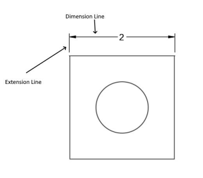
Linear dimensions are expressed on drawings with extension and dimension lines, as shown in Figure 16.10. The extension lines extend from the reference points on the assembly where the measurement is pulled. A dimension line (terminated in arrows) conveys the numbers of the measurement. The extension lines may reference the edge of an object or a feature, but it is not uncommon for dimensions to be pulled from the center of an object such that the dimension line runs from a centerline to an extension line.
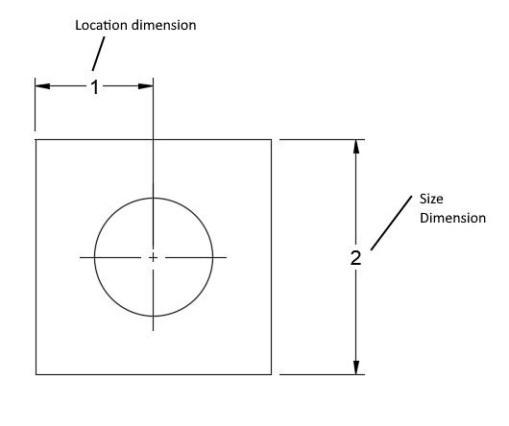
Linear dimensions serve one of two purposes that are necessary for fabrication of the product, and these are the size and location dimensions. Size dimensions communicate the required size of the material while location dimensions call out the location of specific features in relation to some other reference point on the prints.
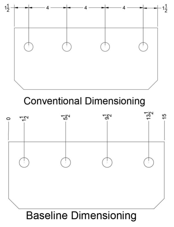
There are two methods for expressing linear dimensions. Conventional dimensioning is what has been shown in the images of this section so far. In this method, two extension and dimension lines are used. Each dimension pulls from one reference point and goes to another. However, in a method called baseline dimensioning, many linear dimensions pull from a single baseline reference or zero point. This method of dimensioning can be recognized by its lack of dimension lines and use of extension lines. Baseline dimensions are sometimes called running dimensions, and the zero point is indicated in one of three ways: a 0, the letters RD (standing for running dimension), or a special symbol shown in Figure 16.12.
Angular Dimensions
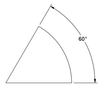
Angular measurements are only necessary in prints when two surfaces lie at an odd angle to one another. If an angular measurement is not present, assume that the edges lie at 90-degrees (square) or 180-degrees (parallel) to one another. It is most common for angles to be given in degrees, even down to tenths (0.1) or hundredths (0.01) depending on the accuracy required.
Diameters and Radii
A radius is the measurement from the center of a circular feature to the outside. A diameter is a measurement all the way across a circular feature—therefore, it is twice the radius.
A diameter is usually given only when the circular feature is a full 360-degrees. If the feature is less than a full circle, a radius is used instead. These measurements will be called out on curved edges or surfaces with a leader line followed by a measurement. Radii measurements are denoted with the letter R. Diameters are sometimes indicated by the letter D but, more commonly, by the symbol pictured in Figure 16.5.

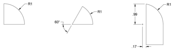
Depending on the complexity of the part being detailed, it may become necessary to provide more than just a radius. Figure 16. 16 shows three examples for the different ways a radius might be detailed.
Let’s explore why each example is dimensioned just so:
- The example on the left is the simplest one, as only a radius of 1 is dimensioned. In this case it is safe to assume that the radius is a full quarter (90-degrees).
- In the middle example not only a radius but an angular dimension is needed since the radius is not an increment of 90-degrees.
- In the rightmost example, linear dimensions are needed to locate the center of the radius. This is necessary when the end or beginning of the radiused part or feature does not lie in line with the center of the circle.
A center mark is used to denote the center of a radius. It looks like a plus sign (+) and can be seen in the rightmost example in Figure 16.16. A center mark may have centerlines extending out from it to aid in dimensioning.
Hole Dimensions
Holes are put into material in order to accept bolts, screws, or other fasteners. Holes are also used for plug welds (see Chapter 15 for more information).
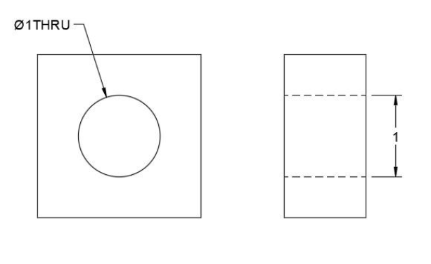
The simplest type of hole is a through hole (often abbreviated “thru”), which goes all the way through the thickness of the material. In prints, their dimensions are called out with a leader line and diameter symbol (see Figure 16.15). If the hole is viewed in a cross section, a linear dimension may be used.
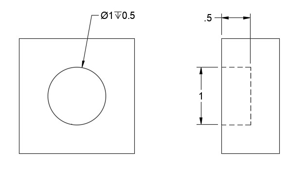
A blind hole is one that does not extend all the way through the material. In prints it is necessary to call out not only the diameter but also the depth of the hole. Depth can be called out on a leader line and may be indicated by the word DEEP, the abbreviation DP, or the symbol shown in Figure 16.18.
Holes that are intended to accept a bolt or other fastener must be prepared in particular ways.
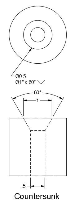
Countersinking is used to make holes that accept fasteners with countersunk heads. The angle of the countersink in the hole must match the angle on the countersunk head of the fastener.
Special countersink cutting tools are used to accomplish this, and they are manufactured at angles of 60-degrees, 82-degrees, 90–degrees, 100-degrees, 110-degrees, and 120-degrees.
When a countersink hole is called for the print must include the diameter of the hole, angle of the countersink, diameter of the countersink at the opening (see Figure 16.21). Rather than the countersink symbol (see Figure 16.20), it may also be called out with the abbreviation CSK.

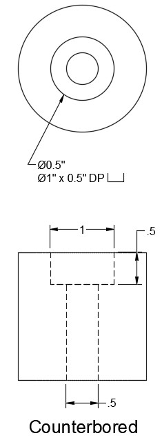
Counterboring is the practice of cutting a large diameter, flat-bottomed hole in line with a small diameter hole. This is done to accommodate flat-headed fasteners, like socket cap screws. The counterbore is drilled deep enough so when the fastener is inserted in the hole the head sits flush with, or below, the surface of the material. Special cutting tools are used for counterboring, and they are made in a variety of diameters and have a pilot pin that ensures the counterbore is centered on the smaller hole.
When a counterbore is required the diameter and depth of the counterbore must be called out. The counterbore symbol may be used (see Figure 16.22), or it may be abbreviated CBORE.

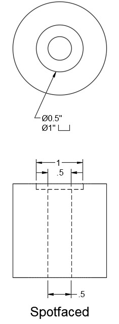
Spot-facing is similar to counterboring, except since it is only used to give a flat, clean mating surface for the head of a fastener, hole depth is not important. Holes may be spot-faced in materials with rough or uneven surfaces or on rounded surfaces. The symbol indicating spot-faces is the same one used for counterbores, though it may also be abbreviated SF.
Attributions
- Figure 16.10: Dimensions & Extra Lines by Cameron Kjeldgaard, for WA Open ProfTech, © SBCTC, CC BY 4.0
- Figure 16.11: Size & Location Dimensions by Cameron Kjeldgaard, for WA Open ProfTech, © SBCTC, CC BY 4.0
- Figure 16.12: Common Running Dimension or Baseline Dimension Symbol by Nicholas Malara, for WA Open ProfTech, © SBCTC, CC BY 4.0
- Figure 16.13: Dimensional Methods by Cameron Kjeldgaard, for WA Open ProfTech, © SBCTC, CC BY 4.0
- Figure 16.14: Angular Dimension by Cameron Kjeldgaard, for WA Open ProfTech, © SBCTC, CC BY 4.0
- Figure 16.15: Diameter Symbol by Nicholas Malara, for WA Open ProfTech, © SBCTC, CC BY 4.0
- Figure 16.16: Radius Dimensions by Cameron Kjeldgaard, for WA Open ProfTech, © SBCTC, CC BY 4.0
- Figure 16.17: Through Hole by Cameron Kjeldgaard, for WA Open ProfTech, © SBCTC, CC BY 4.0
- Figure 16.18: Symbol Denoting Depth Of Drilling In Blind Holes by Nicholas Malara, for WA Open ProfTech, © SBCTC, CC BY 4.0
- Figure 16.19: Blind Hole Dimensions by Cameron Kjeldgaard, for WA Open ProfTech, © SBCTC, CC BY 4.0
- Figure 16.20: Symbol For Countersunk Holes by Nicholas Malara, for WA Open ProfTech, © SBCTC, CC BY 4.0
- Figure 16.21: Countersunk Hole by Cameron Kjeldgaard, for WA Open ProfTech, © SBCTC, CC BY 4.0
- Figure 16.22: Symbol For Counterbored & Spotfaced Holes by Nicholas Malara, for WA Open ProfTech, © SBCTC, CC BY 4.0
- Figure 16.23: Counterbored Hole by Cameron Kjeldgaard, for WA Open ProfTech, © SBCTC, CC BY 4.0
- Figure 16.24: Spotfaced Hole by Cameron Kjeldgaard, for WA Open ProfTech, © SBCTC, CC BY 4.0
Linear dimensions which give the required size of the material
Lines that call out the location of specific features in relation to some other reference point.
A method for giving linear dimensions in technical drawings. In this method two extension and dimension lines are used. Each dimension pulls from one reference point and goes to another.
A method for giving linear dimensions in technical drawings in which many linear dimensions will pull from a single baseline reference or zero point. If this method of dimensioning is used it can be recognized by the lack of dimension lines, baseline dimensions will be carried on an extension line.
